Paramotor, Ansys Fluent CFD Simulation Training
$100.00 Student Discount
In this project, a flow in a paramotor has been simulated, and the simulation results have been investigated.
Click on Add To Cart and obtain the Geometry file, Mesh file, and a Comprehensive ANSYS Fluent Training Video.To Order Your Project or benefit from a CFD consultation, contact our experts via email ([email protected]), online support tab, or WhatsApp at +44 7443 197273.
There are some Free Products to check our service quality.
If you want the training video in another language instead of English, ask it via [email protected] after you buy the product.
Description
Paramotor Project Description
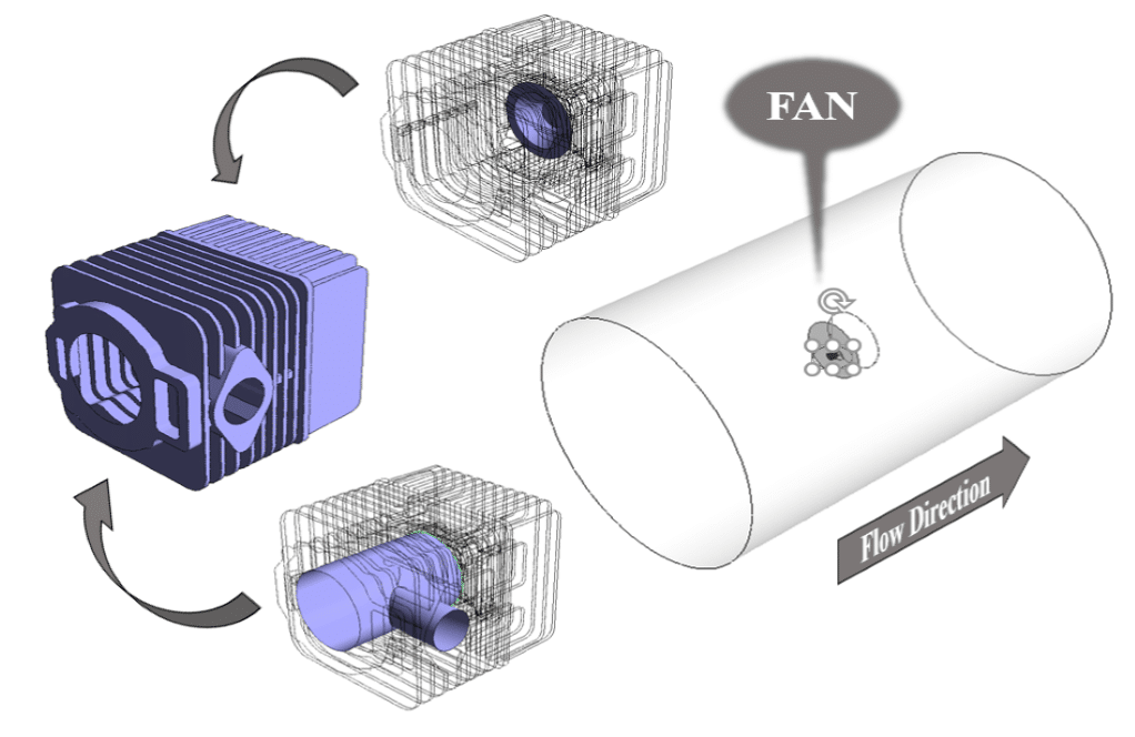
The present simulation is about a paramotor in a paraglider via ANSYS Fluent. A paramotor is the propulsion part of a paraglider that attaches to the pilot’s seat. These engines are powered by gasoline and have fan blades attached to them. This simulation defines a cylindrical computational domain for airflow with a temperature of 26.85 C. For inlet and outlet boundaries of this domain, a pressure boundary condition is defined to determine the direction of air movement according to the amount of pressure. In the middle part of this model, a surface is defined as a fan, and the fan boundary condition with 383.8-pascal pressure jump is used. The aluminum casing of the engine with its thermocouple is defined behind the fan; It is assumed that the inner wall inside the engine has a constant temperature equal to 157 C. It is assumed that this temperature is defined based on the heat generated by the combustion inside the engine.
Geometry & Mesh
The present model is designed in the 3D model via Design Modeler. This model includes a domain designed with a fan in the middle. The following figure shows the geometry of the model.
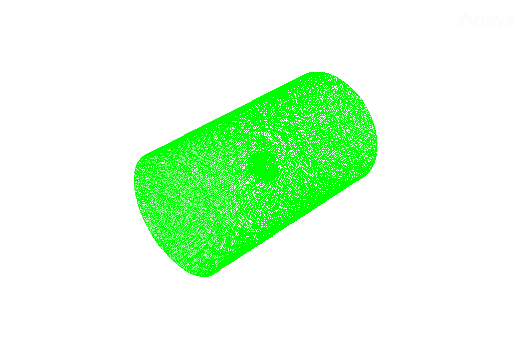
The mesh of the present model has been done via ANSYS Meshing. Mesh is done unstructured, and the number of cells equals 1550207. The following figure shows the mesh of the model.
Paramotor Set-Up & Solution
Assumptions used in this simulation :
- Pressure-based solver is used.
- The present simulation is steady.
- The effect of gravity is ignored.
| Models | ||
| Viscous | k-epsilon | |
| Near-wall | standard | |
| near wall treatment | standard wall function | |
| Energy | On | |
| Boundary conditions | ||
| Inlet | Pressure Inlet | |
| gauge total pressure | 0 pascal | |
| total temperature | 26.85 C | |
| Inner Wall of the Thermocouple | Wall | |
| wall motion | stationary wall | |
| thermal conditions | coupled | |
| Inner Wall | Wall | |
| temperature | 157 C | |
| Outlet | Pressure Outlet | |
| gauge pressure | 0 pascal | |
| Fan | Fan | |
| pressure jump profile | 383.8 pascal | |
| Symmetry Wall | Symmetry | |
| Methods | ||
| Pressure-Velocity Coupling | SIMPLE | |
| pressure | Second-order | |
| momentum | Second-order upwind | |
| turbulent kinetic energy | First-order upwind | |
| turbulent dissipation rate | First-order upwind | |
| energy | Second-order upwind | |
| Initialization | ||
| Initialization methods | standard | |
| gauge pressure | 0 pascal | |
| velocity (x,y,z) | 0 m.s-1 | |
| temperature | 26.85 C | |
Paramotor Results
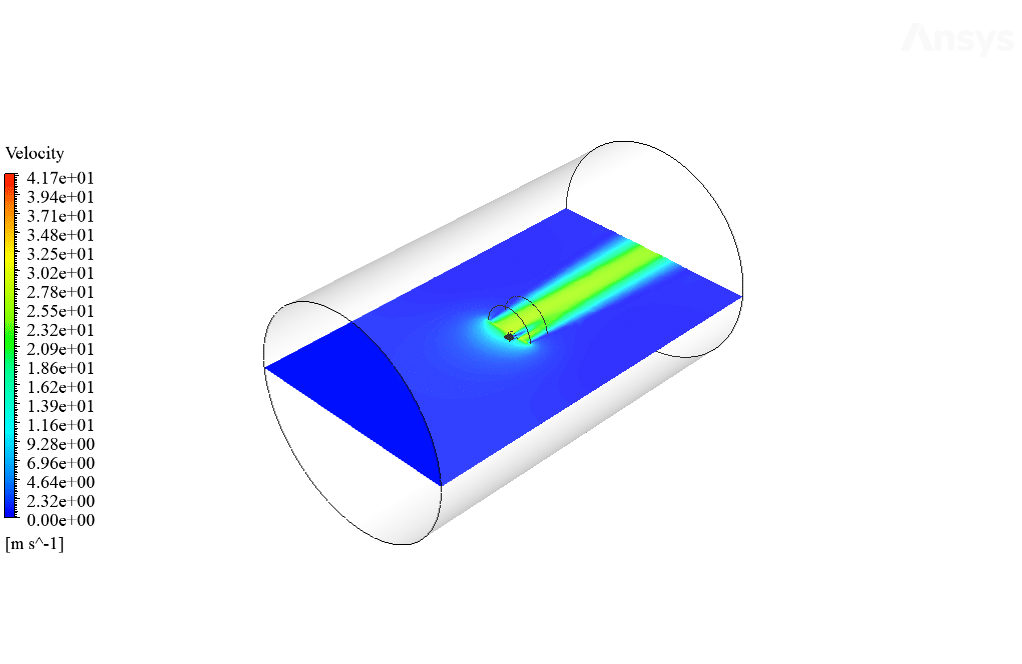
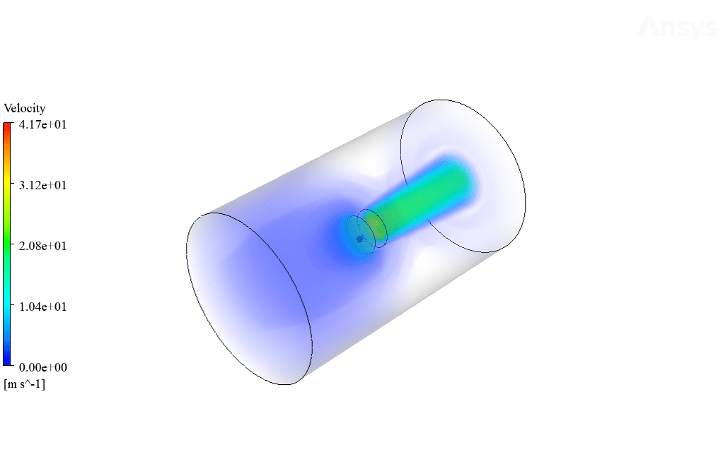
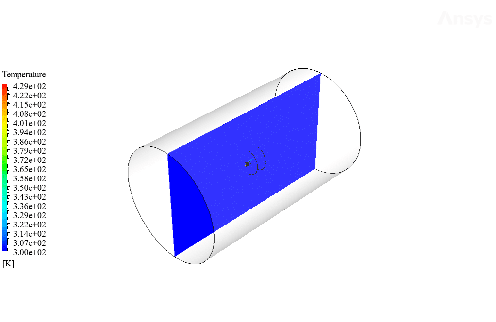
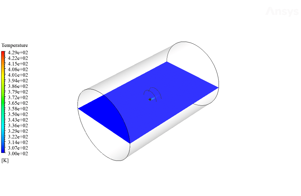
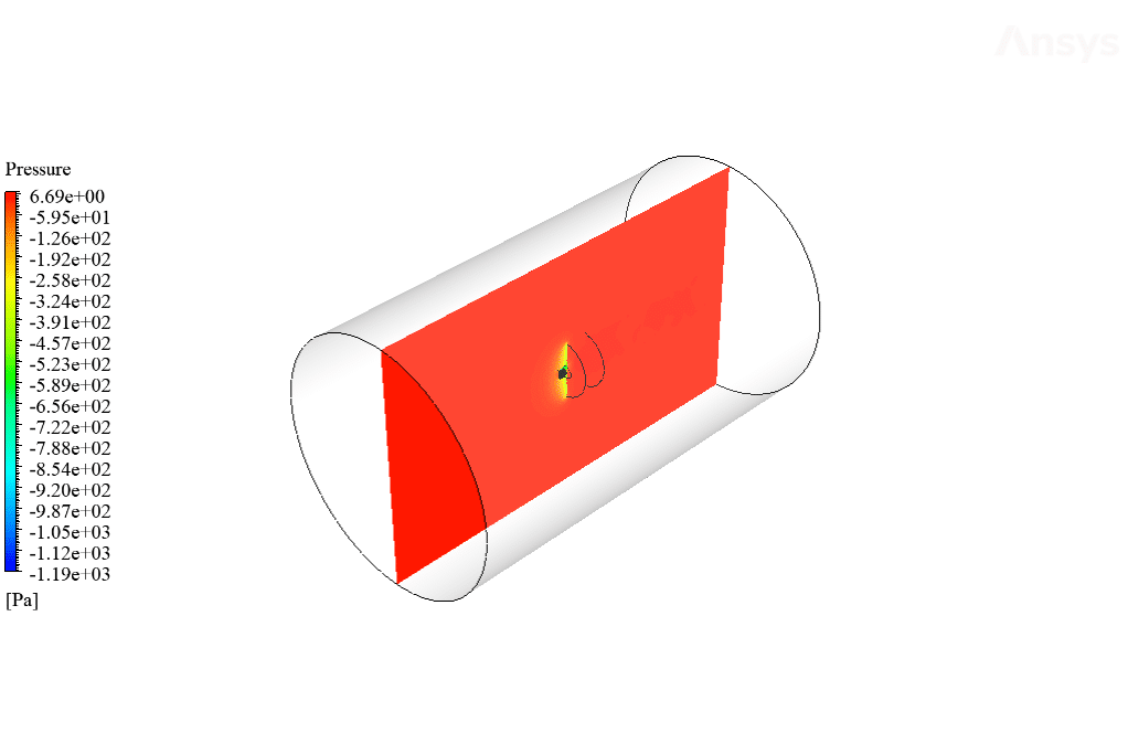
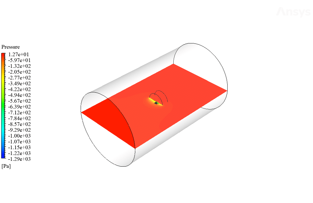
After the solution, 2D and 3D temperature, velocity, and pressure contours are obtained. The contours show that airflow passes through the fan, air velocities increase, and significant pressure differences appear. Around the engine, local temperature increases due to the temperature of the inner wall inside the engine appearing. The results are shown in Figures 3 to 9.
Lucious Carroll –
Does the training include any material on optimizing the design of a paramotor?
MR CFD Support –
Absolutely. The training includes a section on design optimization. This is crucial in improving the performance and efficiency of your paramotor design.
Lenore Barrows –
How does this training handle the complexities of simulating the interaction between the paramotor and the pilot?
MR CFD Support –
The training includes a section on simulating the interaction between the paramotor and the pilot. This is a complex aspect of paramotor simulation and the training is designed to help you understand and simulate it effectively.
Mr. Napoleon Oberbrunner –
Can this training help me understand the impact of different weather conditions on the flight of a paramotor?
MR CFD Support –
Yes, it can. The training includes exercises that explore the impact of different weather conditions, such as wind speed and direction, on the flight of a paramotor.
Ernie Sipes –
What software versions of ANSYS Fluent and DesignModeler were used for this Paramotor simulation? Would this impact my ability to replicate the study with a different version?
MR CFD Support –
The specific versions of ANSYS Fluent and DesignModeler used for the Paramotor simulation were not mentioned in the information provided. Simulation capability can change between versions but the core methodology remains consistent. If you’re using a different version, you may notice slight changes in the interface and features, which could affect your setup and results. For the best possible replication of the study, you should try to use a version as close as possible to the one originally used in the project, or ensure you’re familiar with how differences in version can affect your simulation.
Lizzie Lehner III –
This simulation taught me so much about airflow in paramotors. The detailed setup and results helped clear up a lot of my confusion. Great job!
MR CFD Support –
Thank you for your positive feedback! We are thrilled to hear that our simulation was able to provide you with a clear and detailed understanding of paramotor airflow. If you have any more questions or need further assistance, feel free to reach out. We appreciate your support and hope our products continue to contribute to your learning journey.
Braulio Grant PhD –
The paramotor simulation training was immensely educational. The attention to detail, especially with the boundary conditions and temperature settings, provided a realistic approach to understanding the airflow and its effects. The step-by-step meshing process and the choice of methods reinforced important simulation concepts. It was fascinating to see the practical application of concepts like pressure jumps and thermocouple interactions within a paramotor context.
MR CFD Support –
Thank you for your kind words! We are thrilled to hear that our Paramotor CFD Simulation Training with ANSYS Fluent was able to provide you with a comprehensive and realistic learning experience. It’s great to know that you found the detail-oriented approach and practical applications valuable. We look forward to offering additional training products to assist you in your learning journey!
Katrina Spinka PhD –
Does the training cover how to set up boundary conditions for a simulation?
MR CFD Support –
Absolutely. The training includes a comprehensive section on setting up boundary conditions. This is an essential step in setting up a successful simulation.
Mrs. Taryn Bailey –
I was impressed by the detail in the CFD simulation of the paramotor. Understanding how the airflow interacts with the propulsion system and the resulting temperature distribution helps in optimizing paramotors. Thanks for producing such comprehensive training material.
MR CFD Support –
We really appreciate your feedback! We’re thrilled to hear that our paramotor CFD simulation training delivered the comprehensive insights you needed. Our team strives to provide valuable and detailed simulations to help our customers optimize their designs. If you have any further questions or need more information, don’t hesitate to reach out. Thank you for choosing our training materials!
Camille Robel I –
I’ve used the software as per the tutorial and found it incredibly smooth. As a future engineer, it guided me through setting up and analyzing the paramotor simulation with ease. The clear steps for defining the boundary conditions and the specified temperature for the inner wall were crucial for the simulation and everything worked as intended.
MR CFD Support –
Thank you for sharing your positive experience! We are thrilled to hear that our tutorial for the paramotor CFD simulation in ANSYS Fluent was helpful to you. It’s great that the guidelines on setting up boundary conditions and the inner wall temperature have contributed to a smooth simulation process. We’re proud to serve future engineers like you, and we always strive to provide clear instructions to support your learning journey. Keep on simulating!
Dr. Gladyce Paucek –
The Paramotor CFD simulation training by ANSYS Fluent was incredibly informative! The level of detail in the simulation, from setting proper boundary conditions to analyzing the physical phenomena like pressure jumps and heat generation, provided a strong understanding of thermofluid dynamics in aeronautical applications. The quality of materials, meshing, and final results were top-notch. Highly recommend this for aerospace enthusiasts and CFD practitioners!
MR CFD Support –
Thank you so much for your positive feedback! We’re delighted to hear that you found the Paramotor CFD simulation training incredibly informative and useful. It’s rewarding to know that the detailed approach and thorough analysis provided in the material met your expectations. We look forward to offering other high-quality simulations that can aid in honing your skills. Thanks again for your support!
Prof. Gerson Brekke –
I was absolutely fascinated by the realistic approach this CFD simulation training provided for setting up and solving paramotor computational models in ANSYS Fluent. Percisely capturing the thermal and flow behavior surrounding the paramotor’s engine and the intricacies of the fan interaction highlights the course’s effectiveness. Wonderful learning tool for anyone delving into aerospace simulations!
MR CFD Support –
Thank you for your positive feedback! We’re thrilled to hear you found the paramotor CFD simulation training valuable and effective for understanding aerospace simulations. Your recognition of the realistic approach we’ve implemented is deeply appreciated, and we aim to continue providing quality, hands-on learning experiences in our trainings. Keep exploring and happy simulating!
Prof. Ethan Weimann III –
The artwork showcases the practical implementation of scientific principles in action with the paramotor. The meticulous design appeals to both my interest in flight mechanics and my appreciation for well-crafted simulation tasks.
MR CFD Support –
Thank you for your positive feedback on the Paramotor simulation project. We are glad to hear that not only was it instructional but also that the dedication to detail and scientific accuracy in the project resonated with your interests. If you have further inquiries or need additional guidance in flight mechanics or simulation studies, feel free to reach out!
Miss Amara Towne IV –
I used the paramotor CFD simulation training materials and the detailed approach made it really intuitive! Understanding the complicated interactions within the simulation became so much more straightforward. Great job on presenting complex concepts in a discernible way!
MR CFD Support –
Thank you for your positive feedback! We’re delighted to hear that our Paramotor CFD simulation training materials helped clarify complex concepts for you with an intuitive approach. Your comments are incredibly appreciated, and they motivate us to continue providing high-quality learning experiences. Keep learning and stay in touch with any further educational needs you might have!
Mrs. Roma Torp II –
I really enjoyed the level of detail in the simulation of the paramotor’s airflow dynamics. The temperature and pressure contours provided a clear understanding of the complex interactions between the air and engine thermodynamics.
MR CFD Support –
Thank you so much for your kind words! We are thrilled to hear that the details in the paramotor’s airflow dynamic simulation were helpful and that the temperature and pressure contours met your expectations. We always strive to provide clear and comprehensive simulations, and your feedback is greatly appreciated.
Terrell Hoeger DDS –
Great work on conducting the Paramotor simulation and explaining the setup details clearly. The assumptions listed really helped to understand the modelling and the process. It’s impressive how the simulation takes into account so many detailed conditions like the pressure jump for the fan and the engine thermocouple’s heat. The results must provide valuable insights into the performance and behavior of actual paramotors.
MR CFD Support –
Thank you for your positive review. We’re delighted to know that our detailed setup and the assumptions about the simulation provided you with a clear understanding of the paramotor’s behavior. Insightful results are what we aim for, and we’re glad that the simulation met your expectations. Your feedback is much appreciated!
Kelsie Turcotte –
The Paramotor simulation seems incredibly detailed. Fantastic to see how it models the airflow and engine temperature. Keep up the good work!
MR CFD Support –
Thank you for your kind words! We’re so pleased to hear you appreciate the details and work that go into our simulations. Understanding the airflow and temperature conditions in the Paramotor simulation is crucial, and we’re glad you found it impressive. If you have any more feedback or need further assistance, don’t hesitate to reach out.
Cullen Vandervort –
The course was incredibly detailed and practical for understanding paramotor simulations. The step-by-step guide through geometry, mesh, setup, and the analysis of results was excellent. The visuals in the results made the complex data easy to grasp.
MR CFD Support –
We’re thrilled to hear that you found the Paramotor CFD Simulation Training course practical and informative. Thank you for appreciating the step-by-step guidance and the visual representations of results in the course. We hope that it has enhanced your simulation skills.