
Point Cloud Based Airfoil Geometry Reconstruction for CFD Simulations
Free
- Point Cloud data serves as the foundation for reconstructing accurate 2D and 3D geometries.
- By converting raw coordinate points into smooth surfaces, simulations achieve higher precision.
- Point Cloud processing enhances meshing quality and avoids geometric inconsistencies.
- This approach ensures reliable results in CFD and other engineering analyses.
To Order Your Project or benefit from a CFD consultation, contact our experts via email (info@mr-cfd.com), online support tab, or WhatsApp at +44 7443 197273.
There are some Free Products to check our service quality.
If you want the training video in another language instead of English, ask it via info@mr-cfd.com after you buy the product.
Description
Point Cloud Based Airfoil Geometry Reconstruction for CFD Simulations
Introduction
This project focused on training and gaining practical experience in the full workflow of computational fluid dynamics (CFD) simulation using ANSYS. The work involved creating geometry directly from airfoil data, importing and refining it in CAD environments, generating the computational domain, meshing, and solving the governing equations in ANSYS Fluent. A key part of this workflow was the use of point cloud data to define the airfoil geometry with precision. Through this study, we developed essential skills in curve creation, geometry handling, and the numerical simulation of aerodynamic performance.
Geometry Creation in CAD (Curve → Surface → Domain)
The geometry creation stage began with obtaining airfoil coordinate data, often provided as a point cloud containing raw x–y values. To ensure smoothness and continuity, the point cloud was first processed in Microsoft Excel to remove redundancies and sort the data correctly. CAD programs require ordered and consistent input, so this preparation was crucial.
In DesignModeler (3D Curve Tool):
The processed point cloud was saved into a structured file (e.g., modeler-2.txt) with appropriate columns for point index and coordinates. DesignModeler then imported these points and connected them as a spline curve, reconstructing the 2D shape of the airfoil from the point cloud. To work correctly, the order of points had to follow a trailing-edge → upper surface → leading edge → lower surface → trailing-edge cycle.

In SpaceClaim (Polyline Import Style):
SpaceClaim required a slightly different file format, where the point cloud was processed into polyline-friendly input. With settings such as 3d=true and fittol=0.01, the software was able to fit smooth curves directly to the imported point cloud. This provided greater flexibility for editing and rapid adjustments, although it depended on careful tolerance settings to avoid distorted geometry.
After the point cloud data was converted into curves, surfaces were generated to represent the airfoil profile. A rectangular computational domain was then created around the geometry to simulate the far-field environment. Boolean subtraction was used to exclude the solid airfoil shape, leaving only the surrounding fluid domain for CFD analysis.
This step emphasized a key learning outcome: DesignModeler favors structured workflows tied to ordered point cloud inputs, while SpaceClaim offers flexible handling of point cloud geometry with tolerance-based polyline fitting. Both are valuable skills for industrial CFD applications.

Meshing
The fluid domain containing the embedded airfoil surface was imported into ANSYS Meshing. A tetrahedral mesh was generated with about 21,000 elements. Refinement was applied close to the airfoil walls to resolve boundary layer gradients accurately, while a coarser mesh was used in the far-field. The mesh design ensured a good balance between capturing the physics correctly and keeping computational costs reasonable. The well-prepared point cloud geometry ensured smooth meshing with no gaps or jagged edges.
CFD Setup in Fluent
The mesh was loaded into ANSYS Fluent and solved using a steady-state, pressure-based solver. The k–ω SST turbulence model was chosen because it predicts boundary layer separation effectively around aerodynamic bodies. Boundary conditions were:
Inlet: Velocity inlet set to 10 m/s
Outlet: Pressure outlet at 0 Pa gauge pressure
Airfoil walls: No-slip condition
These inputs modeled external aerodynamics at low speed. The use of point cloud derived geometry ensured that the flow domain closely matched the intended physical airfoil shape.
Results and Discussion
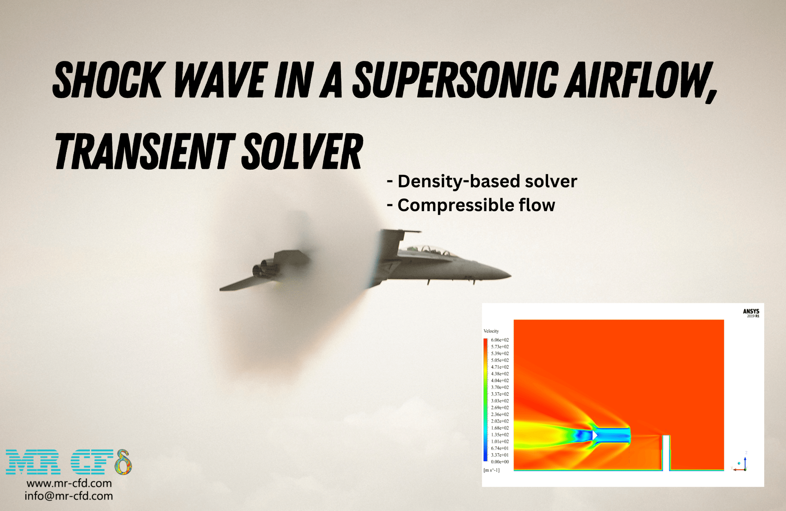
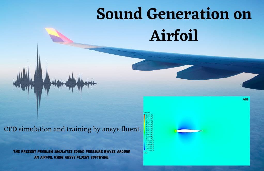
The simulation results demonstrated classical airfoil behavior. Pressure contours showed a high-pressure zone at the leading edge and a low-pressure distribution on the upper surface, generating lift. Velocity plots confirmed that the flow accelerated to about 11.5 m/s above the suction surface, while it slowed slightly on the pressure side. Streamline visualizations showed attached, stable flow without major separation regions.
It was evident that the high-quality point cloud – processed into smooth surfaces – played an important role in obtaining realistic aerodynamic results. Poorly defined point cloud data could have introduced geometry errors or distorted patterns in the pressure/velocity contours.
Conclusion
The CFD simulation captured the aerodynamic characteristics of the airfoil successfully. Pressure and velocity plots confirmed airflow acceleration on the suction side and pressure recovery downstream, consistent with aerodynamic theory. The absence of flow separation highlighted that the setup and mesh were both reliable.
You must be logged in to post a review.


Reviews
There are no reviews yet.