
Sound Generation on an Airfoil, 3 Different Attack Angles
$140.00 Internship
- The problem numerically simulates the Sound Generation on Airfoil using ANSYS Fluent software.
- We design the 3-D model with the Design Modeler software.
- We mesh the model with ANSYS Meshing software.
- The mesh type is Structured, and the element number equals 231840.
- This project has been done in three modes with different angles of attack for airfoils.
- We use the Broadband Noise Sources model to define the Acoustic model.
To Order Your Project or benefit from a CFD consultation, contact our experts via email (info@mr-cfd.com), online support tab, or WhatsApp at +44 7443 197273.
There are some Free Products to check our service quality.
If you want the training video in another language instead of English, ask it via info@mr-cfd.com after you buy the product.
Description
Sound Generation on an Airfoil, 3 Attack Angles CFD Simulation, ANSYS Fluent Acoustic Model Training
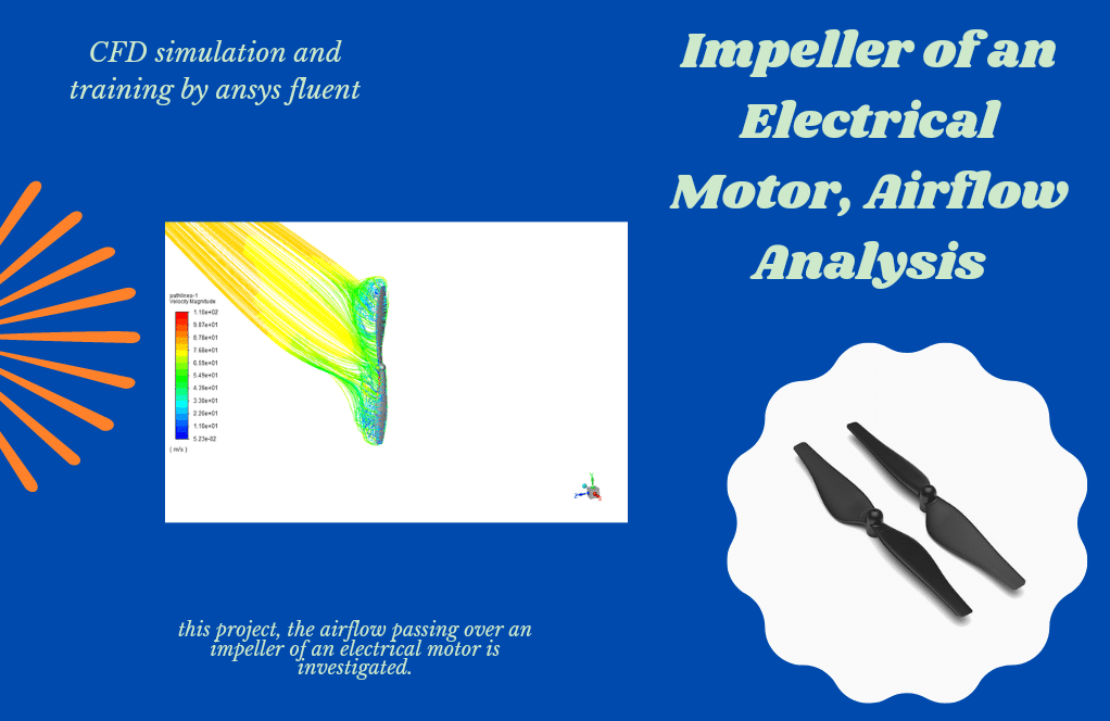
The problem simulates sound pressure waves around an airfoil using ANSYS Fluent software.
Topics related to sound waves are very important in aerospace applications and fields; Because the sound waves produced in aerospace devices such as airfoils are very high. This project examines the sound waves generated around the body of an airfoil.
This project uses an acoustic model in Fluent software to simulate and analyze sound or acoustic waves. Definitive density is equivalent to air density, i.e., 1.225 kg / m3. Sound speed is equivalent to sound speed in the air, i.e., 340 m / s, and the reference acoustic power equals 1e-12 pascal.
In this modeling, the NACA0012 type airfoil is designed, and the airflow moves towards this airfoil with a speed equal to 68 m/s.
This project has been done in three modes; So, the airfoil’s angle of attack in these three cases is equal to 0, 7, and 14 degrees, respectively. The angle of attack is equal to the direction of the wind direction with the airfoil chord.
The present model is designed in two dimensions using Design Modeler software. The model includes a NACA0012 airfoil located inside a computing environment with a maximum length and width of 400 m and 200 m.
The airfoil chord length is equal to 1 m and is designed horizontally. To simulate airfoils, you should use the Airfoil Tools website and receive the set of coordinates of the constituent parts of the airfoil body in the form of a point cloud and import it into the Design Modeler software.
The meshing has been done using ANSYS Meshing software, and the mesh type is structured. The element number is 231840.
Sound Methodology
The Broadband Noise Sources model has also been used to define the type of acoustic model of the present work.
Sound Conclusion
At the end of the solution process, two-dimensional contours related to pressure and velocity and diagrams of changes in velocity and acoustic power level in all three states are obtained from different attack angles.
The figures show the change in acoustic power level (dB) or the amount of sound pressure in terms of location in the longitudinal direction. This location indicates a few meters before the location of the airfoil body, then on the surface of the airfoil body, and finally a few meters after the airfoil body.
As it turns out, the sound wave is generated after the airflow hits the airfoil body. According to the figures, it can be said that when the airfoil’s angle of attack is zero, the sound is propagated at a greater distance after the airfoil. However, the more the angle of attack, the more amplitude indicates the sound is more limited.
Reviews
You must be logged in to post a review.

Wilfred Hickle –
What are the practical applications of knowing the acoustic power levels from different attack angles on an airfoil?
MR CFD Support –
Acoustic power levels derived from varying attack angles on an airfoil have multiple applications in the design and operation of aerospace vehicles. They can be crucial for noise control, improving passenger comfort in commercial aviation, and confirming regulatory compliance. For military aircraft, understanding these noise signatures can affect detection and stealth capabilities. Additionally, studying the effects of aerodynamic noise is important for optimizing airfoil efficiency and for structural health monitoring to prevent fatigue from aerodynamic stresses.
Dr. America Wolff –
The descriptions of the sound simulations are fantastic! Really appreciate how thorough and detailed they are, especially how the sound waves’ behavior changes with different angles of attack. This is quite valuable for anyone studying aerodynamics or noise pollution in aerospace engineering.
MR CFD Support –
Thank you so much for your kind words! We’re thrilled to hear that you found the simulations detailed and informative. If you ever have more questions or need further information, feel free to reach out. We’re here to help!
Dahlia White –
I was really impressed with the detailed analysis of sound generation at different attack angles on the airfoil. The visualization of sound pressure levels helped me understand the impact of attack angle on noise generation. It’s fascinating how the sound waves vary with the angle, especially for aerospace applications where noise levels are crucial.
MR CFD Support –
Thank you for your positive feedback! We are thrilled to hear that our simulation helped you gain a better understanding of the relationship between attack angle and sound generation on an airfoil. At MR CFD, we always strive to provide detailed and visually informative content. Your insights highlight the value of our acoustic modeling efforts. We appreciate your appreciation and look forward to offering more educational and practical CFD analyses in the future.
Dayana Schneider –
The entire training is impressive! The details on dealing with acoustic simulation for different angles of attack provide substantial insights for aerospace applications.
MR CFD Support –
Thank you for your kind words! It’s great to hear that our training on acoustic simulations for different angles of attack has provided valuable insights for those interested in aerospace applications. We appreciate your feedback and are glad that you found the information impressive and useful.
Elisabeth Pfannerstill –
I found the acoustic power level data and how it changes with the angle of attack very insightful. It’s interesting to see how sound propagation changes in each scenario.
MR CFD Support –
We’re glad to hear that you found the data concerning the acoustic power level informative and intriguing! Understanding the nuances of how sound behaves under different conditions is key in aerospace and other engineerings. If you have any further questions or require additional insights, don’t hesitate to reach out. Thank you for your positive feedback!
Cali Quitzon –
I was fascinated by how the angle of attack affects sound generation. How well does the model predict noise levels for higher angles like beyond the 14 degrees studied?
MR CFD Support –
The model is calibrated to predict noise levels accurately for the angles studied. Since it has been tested for 0, 7, and 14 degrees attack angles, it would require additional simulations and validations for angles beyond 14 degrees to ensure the acoustic model’s predictions are as precise for higher angles of attack.