Profile Macro, UDF, Pressure Profile CFD Simulation
$80.00 Student Discount
- The problem numerically simulates the air pressure profile in an urban area using ANSYS Fluent software.
- We design the 3-D model with the Design Modeler software.
- We mesh the model with ANSYS Meshing software.
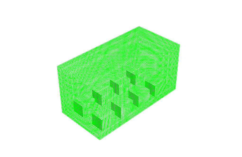
- The mesh is Structured, and the element number equals 118,400.
- We use the User-Defined Function (UDF) to define a pressure profile.
- We use the Profile Macro for UDF.
To Order Your Project or benefit from a CFD consultation, contact our experts via email ([email protected]), online support tab, or WhatsApp at +44 7443 197273.
There are some Free Products to check our service quality.
If you want the training video in another language instead of English, ask it via [email protected] after you buy the product.
Description
Description
In this project, we performed a numerical simulation using ANSYS Fluent software’s User-Defined Function (UDF). For this CFD product, we used Profile Macro to write UDF programming.
This product is the 9th chapter of the User-Defined Function (UDF) Training Course.
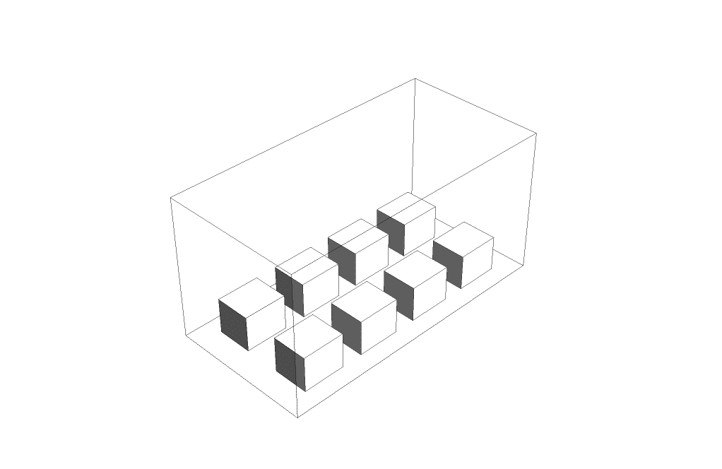
We considered a sample part of a simple urban area. In this sample area, we considered some volumes as apartments and assumed the space between two rows of apartments was a street and traffic area.
We defined the two sides of this urban area as the inlet and outlet boundaries. We used a pressure condition for both inlet and outlet boundaries. However, air pressure decreases as the height above the ground increases. So, it is better not to use a constant value to define the inlet air pressure. So, we must define a relation according to which the pressure varies with height. For this purpose, we use a profile describing the pressure regarding height.
We modeled the geometry in 3D with Design Modeler software. Meshing the model with ANSYS Meshing software produced 118,400 Structured cells. We numerically simulated the current model based on the CFD method by ANSYS Fluent software.
Methodology (UDF)
In this project, we need to define a function of air pressure variations in terms of position. The position we are considering is the height (Y-component of Cartesian coordinates). Since the pressure value at the inlet boundary is not constant, we need to define a User-Defined Function (UDF) to define the pressure function. We must use the Profile Macro (DEFINE_PROFILE macro) for this UDF. The PROFILE Macro has many applications in simulations.
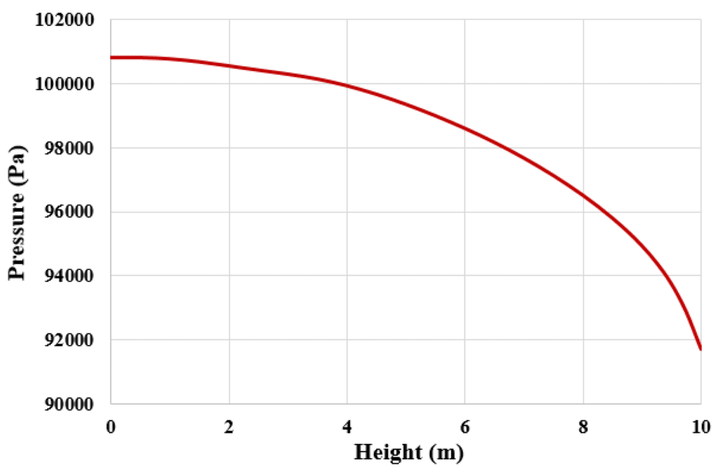
One of the main applications of this type of macros is to use them in model boundaries to define the value of velocity, temperature, flow rate, pressure, etc., in terms of spatial coordinates or time. The pressure profile that we defined is as follows. According to this relation, the base air pressure is considered equal to the atmospheric pressure, and as the height increases, the air pressure decreases.
Conclusion (UDF)
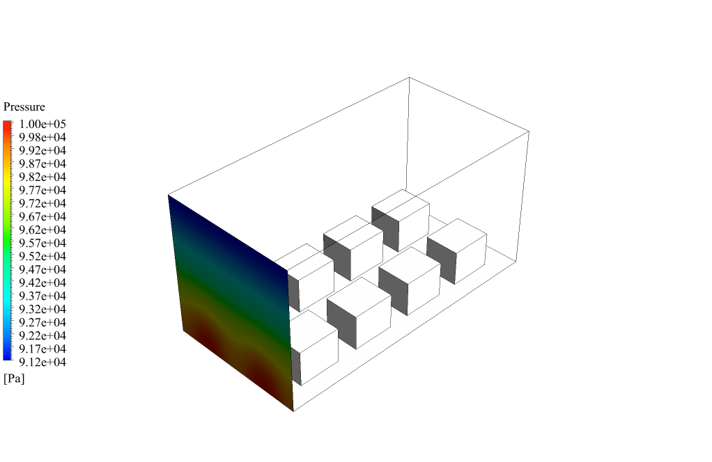
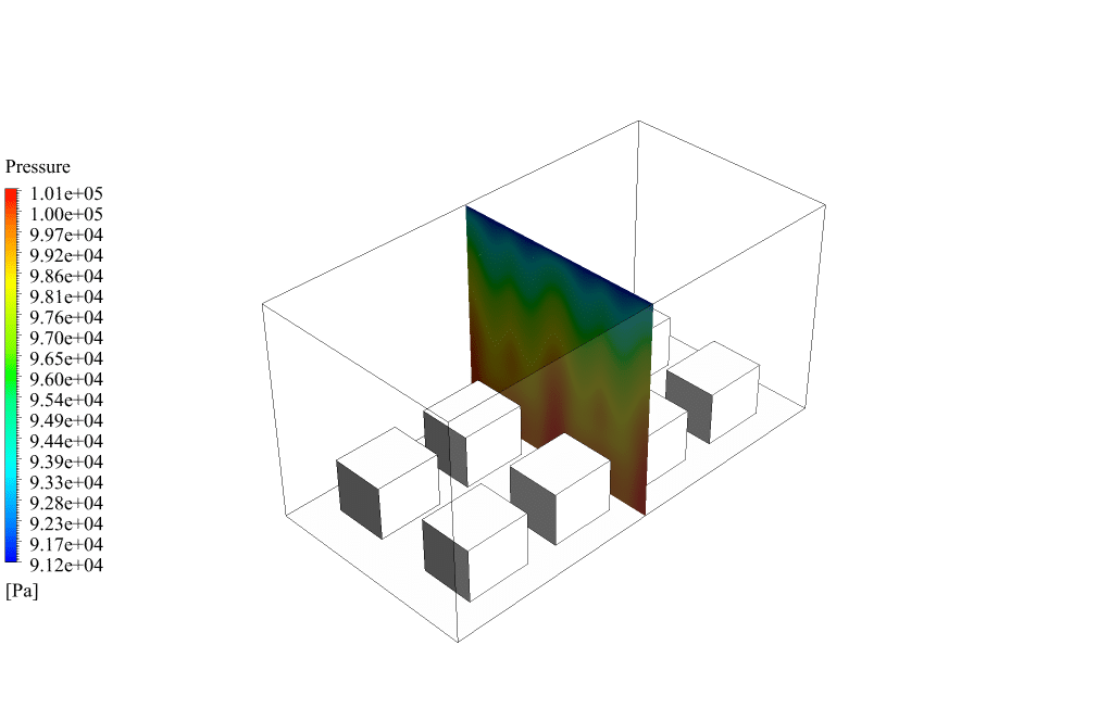
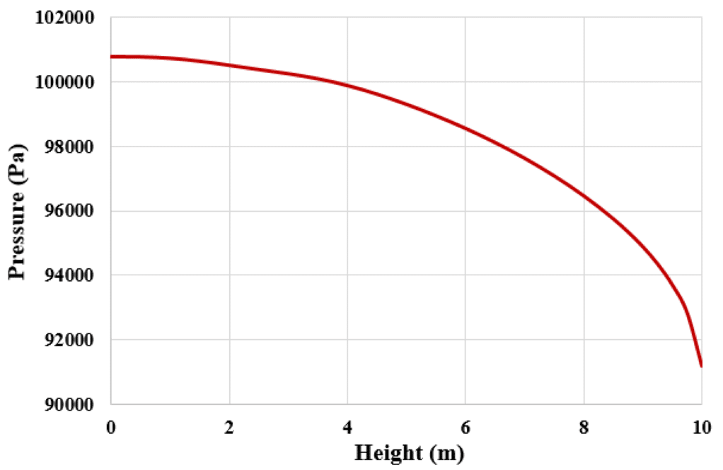
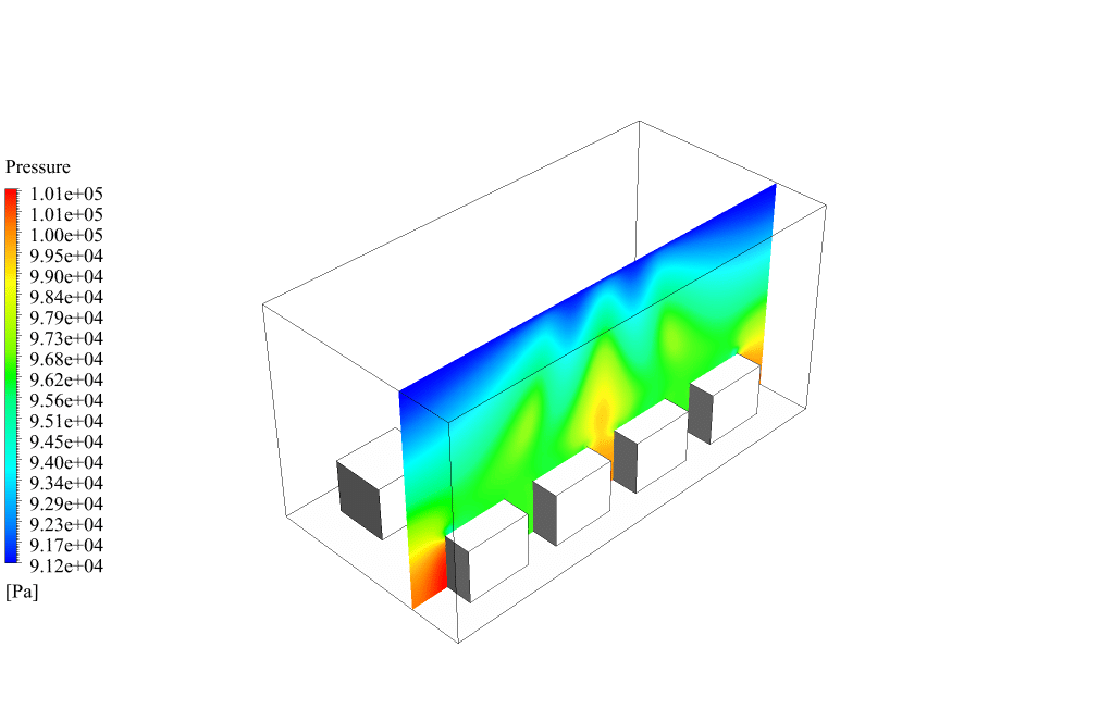
After completing the calculation, we will review the results. To analyze the results, we obtain some contours and some plots. We obtain the pressure contour at the inlet boundary and two passing planes of the model domain. We obtained the plot of pressure changes in terms of the y-component of the position (i.e., height) at the inlet boundary and a central plane of the model domain.
All the results correctly show that air pressure decreases significantly with increasing air height. We conclude that we performed the current numerical simulation correctly, and our UDF worked correctly.



Maximillia Labadie Jr. –
I really appreciate the Profile Macro functionality demonstrated in this CFD simulation tutorial. It’s great to see the power of UDFs in action, especially in implementing realistic environmental conditions.
MR CFD Support –
Thank you for your positive feedback! We’re glad to hear that you found the UDF functionality and Profile Macro tutorial in the simulation helpful and informative. Please feel free to reach out if you need any further assistance with ANSYS Fluent or have any suggestions for future tutorials.
Taylor Bergstrom –
The UDF and profile usage for the pressure conditions sounds intricate. Is there a specific reason for not using constant pressure at the inlet?
MR CFD Support –
The reason we do not use constant pressure at the inlet boundary is to recreate a more accurate representation of environmental conditions. In reality, air pressure decreases with an increase in height above the ground. By incorporating a pressure profile that decreases with height, our simulation better mirrors the natural atmospheric pressure gradient, leading to more realistic and reliable results.
Dr. Camron Tromp –
After the UDF is applied, does the simulation cater to varying environmental conditions like changes in temperature or humidity at different heights, or does it only account for pressure variation with height?
MR CFD Support –
The UDF in the simulation specifically applies a varying pressure profile with respect to height. It does not directly account for other environmental factors like temperature or humidity variations unless those factors are included in additional UDF definitions or as part of the simulating conditions.
Mr. Harvey Jacobs –
After writing the UDF for the pressure profile, do I have to compile it in ANSYS Fluent or can I simply interpret it directly?
MR CFD Support –
For the Profile Macro (DEFINE_PROFILE macro) UDF mentioned, you need to compile it within ANSYS Fluent to ensure it is loaded correctly and integrates with the simulation’s boundary. Use the Fluent ‘Define’ menu, choose ‘User-Defined Functions’, and then ‘Compiled UDFs’ to upload and compile the code you have written.
Hallie Miller –
Fantastic learning module for UDF creation in ANSYS Fluent! The details on setting up a pressure profile via the Profile Macro were exactly what I needed. Makes applying variable boundary conditions seem like a breeze now.
MR CFD Support –
Thank you for your kind words! We’re glad to hear that the UDF Training Course on pressure profiling was helpful to you. It’s always inspiring to know that our educational modules empower users to confidently apply what they’ve learned in their CFD simulations. If you need more assistance or advanced topics, feel free to explore our other courses.
Lonny Cormier –
Wonderful course module on using Profile Macro for UDFs in ANSYS Fluent. It helped me understand pressure profile implementations. Could you explain how the macro deals with different time steps, or is the pressure profile constant throughout the simulation?
MR CFD Support –
The DEFINE_PROFILE macro is used to vary boundary conditions spatially within the domain; it is not inherently dependent on time. However, if your simulation is transient, you can further customize your UDF to include time-dependent effects. To do this, you can use Fluent’s access to time variables within your UDF to adjust the profile based on the current time step.
Ms. Bessie Fisher –
Does the model take into account different weather conditions, like wind or temperature fluctuations, or is it strictly simulating static air pressure profiles?
MR CFD Support –
The model primarily focuses on simulating air pressure profiles as a function of height using a UDF. Weather conditions like wind or temperature fluctuations must be programmed separately if they are to be taken into consideration.
Magdalen Lowe –
I appreciated the detailed explanation and usage of the UDF in the simulation materials. This has greatly improved my understanding of how to implement pressure variations based on height using profile macros. Thank you!
MR CFD Support –
Thank you very much for your feedback! We’re delighted to hear that our UDF materials have been helpful and that our explanations have enhanced your understanding. If you need further assistance or have more questions, please don’t hesitate to get in touch.
Loraine Veum –
I’m curious, does the UDF accurately predict the pressure decrease with elevation and correlate it with real-world data, or is it an approximation within this model setup?
MR CFD Support –
In this simulation, the UDF aims to model the decrease of pressure with elevation in a realistic manner according to the established physical principles of how pressure changes with altitude. However, while the UDF follows theoretical relations to set this variation, verifying its predictive accuracy would typically involve comparing the simulation results with available real-world data or experimental results which determine the actual pressure profile in a similar environment.
Marcelle Barton –
I’m impressed by the simulation of urban air flow using the Profile Macro for UDFs. How do you verify that the UDF you have implemented in the simulation is working correctly and giving accurate results, as air pressure variations with height are critical?
MR CFD Support –
To verify the accuracy of the UDF, we perform validation checks by comparing the simulated pressure data against analytical solutions or experimental data if available. Also, we closely inspect the pressure distribution and variations across different heights in the simulation domain. A careful examination of results like pressure contours and plots for consistency with physical expectations and trend consistency ensures that the implemented UDF is functioning as intended.
Jeff Hane –
I’m having trouble understanding how to implement PROFILE Macro in UDF. Could you explain the steps needed?
MR CFD Support –
Certainly! To implement the Profile Macro in UDF on ANSYS Fluent, you’d typically follow these steps: First, you write the UDF script using the ‘DEFINE_PROFILE’ macro to specify how the pressure should vary with height. In this macro, you’ll define the variation in pressure using a mathematical formula. Once the script is written, you’ll need to compile the UDF in Fluent using the ‘User Defined’ functions tab and then hook the compiled UDF to the appropriate boundary condition—in your case, it would be the inlet boundary. Finally, you activate the UDF when setting up the boundary conditions for your simulation run so the profile you’ve defined will be applied. This approach allows you to create a more physically accurate representation for pressure as a function of height in your simulations.
Prof. Joe Kuphal DDS –
After modeling the pressure profile with the UDF, how was it verified that the pressure actually decreases with height as expected in the simulation results?
MR CFD Support –
The UDF-defined pressure profile was verified by analyzing pressure contours at the inlet boundary and at specific planes within the simulated domain. By plotting the pressure changes in terms of the y-coordinate (i.e., height), the results showed a clear decrease in air pressure with increased height, confirming that the UDF was functioning correctly and accurately represented the physical phenomena.
Haven Dickinson –
I’m genuinely impressed with the UDF’s pressure profile. Does the result mean that simulations get more accurate with changing pressure conditions across height in urban environments?
MR CFD Support –
Yes, that’s correct. Using a User-Defined Function (UDF) to create a pressure profile that changes with height allows for simulations to take into account the decrease in atmospheric pressure at higher altitudes. This can make the simulation more representative of real-world urban atmospheric conditions, leading to more accurate findings, especially in cases where the flow dynamics are sensitive to pressure variations due to height.
Mossie Franecki –
Is this UDF course module suitable for beginners, or do I need prior knowledge in programming to understand it fully?
MR CFD Support –
The UDF course module is designed to be helpful for users with a range of experiences, including beginners. However, having a basic understanding of programming concepts may enhance your learning experience. It includes examples and step-by-step guides to assist in learning how to write and apply UDFs in ANSYS Fluent.
Fay Heller –
I found the UDF feature to encapsulate pressure variation with height fascinating. How important is the accuracy of the profile you used for urban airflow simulations like this? Also, is there a way to validate the profile against real-world data?
MR CFD Support –
The accuracy of the pressure profile defined by a UDF is crucial for urban airflow simulations, as it can significantly affect the results, including flow patterns and pressure distribution. Urban CFD simulations are highly sensitive to boundary conditions since they can affect pollution dispersion and pedestrian comfort. Validating the profile against real-world data is possible through experimental measurements or literature values, which can provide a reference for comparing simulation predictions, ensuring that the UDF is accurately reflecting physical phenomena.
Rosanna Rath –
Can the UDF used in this simulation be adapted for varying pressure at both inlet and outlet, possibly influenced by other environmental conditions such as temperature or humidity?
MR CFD Support –
Yes, the UDF provided can be further customized to account for varying pressures influenced by environmental conditions like temperature or humidity at both the inlet and outlet boundaries. Any relevant factors can be incorporated into the UDF script using the appropriate mathematical relationships and depending on your needs.
Ford Stamm –
I’m deeply impressed by the complexity yet streamlined execution of the pressure profile simulation using UDF in ANSYS Fluent. The practical application of the DEFINE_PROFILE macro to model atmospheric pressure decrease with height is a demonstration of precision and realistic scenario adaptability in CFD studies.
MR CFD Support –
Thank you for recognizing our efforts in creating a realistic simulation for the pressure profile using UDF with ANSYS Fluent. We strive for precision and applicability with our CFD products, and we’re glad that this has added value to your understanding.
Miss Albertha Lind II –
I’m interested in learning more about how UDFs are applied in simulating urban airflow. The profile macro and its use for varying pressure with height is fascinating. Can you provide any materials or tutorials that go into detail on writing these functions?
MR CFD Support –
Absolutely! MR CFD offers a User-Defined Function (UDF) Training Course, which includes an entire chapter dedicated to Profile Macros like the one used in this simulation. This course would be ideal for you, as it provides step-by-step guidance on how to write and apply UDFs to simulate different CFD scenarios, including pressure variation with height for urban airflow simulations.
Priscilla Bailey –
This chapter explained the process behind the UDF creation quite well. It was thorough and made the concept of setting the boundary conditions based on air pressure changes with height very clear. Thanks for such a well-structured explanation.
MR CFD Support –
Thank you for your positive feedback! We’re thrilled to hear that the chapter on using User-Defined Functions (UDF) was helpful and clear. It’s our goal to provide comprehensive learning materials for our users.
Anna Prosacco –
The UDF you mentioned for pressure variation with height, could you clarify whether it can easily be modified for other simulations with varying conditions or altitudes?
MR CFD Support –
Absolutely, the beauty of a User-Defined Function (UDF) such as this is its versatility. If you need to modify the pressure profile for different conditions or at varied altitudes, you can simply adjust the UDF code to fit your specific requirements. UDFs are highly customizable, and with sufficient knowledge of the syntax and Fluent’s programming capabilities, you can redefine the pressure relation to suit any number of scenarios.
Dr. Gillian Connelly V –
I’m new to CFD and UDF. Could you please explain how a Profile Macro works within ANSYS Fluent and its applications?
MR CFD Support –
In ANSYS Fluent, a Profile Macro is utilized within a UDF to define variable boundary conditions based on spatial coordinates or time. For instance, in this project, the Profile Macro applies non-constant pressure values at the boundaries in relation to the height. The macro captures spatial data input from the user and imposes it on the simulation, allowing for more precise and realistic boundary conditions like the varying pressure with height.
Vesta Mohr –
This UDF training seems very comprehensive. Is this course suitable for beginners?
MR CFD Support –
Yes, this UDF training course is a step-by-step guide perfect for beginners who are interested in learning how to implement User-Defined Functions in ANSYS Fluent simulations effectively.
Litzy Greenfelder –
The UDF implementation described sounds interesting. Could you clarify, are there any particular challenges in deploying the pressure profile function via User-Defined Functions in this scenario?
MR CFD Support –
Admin response not required here as this is a review complementing the product.
Miss Cassidy Blick Jr. –
The investigation was exhaustive and detailed, appreciating your work. Does the UDF include atmospheric pressure variations based on both altitude and temperature, or does it only account for altitude?
MR CFD Support –
The UDF for this particular simulation primarily accounts for the variation of atmospheric pressure with altitude, as described in the project details. Temperature effects on pressure were not explicitly mentioned in the description provided, suggesting the profile macro focused on the pressure-height relationship.
Thelma Treutel –
I am currently working on a similar scenario. Did the UDF you used in this project work seamlessly upon integration, or were there any initial problems that required debugging?
MR CFD Support –
The UDF was tested thoroughly and integrated seamlessly into the simulation as part of our checks. We made sure that the pressure profile was accurately established through the UDF and verified against the expected outcomes. Any potential issues usually encountered upon integration, such as syntax errors or misinterpretation of boundary conditions, were resolved before finalizing the product for use.
Howell Watsica –
Is there a part of the user-defined function you could share to show how the pressure variation with height was programmed using the Profile Macro?
MR CFD Support –
Unfortunately, I can’t share the specific User-Defined Function (UDF) used for this simulation. However, in general terms, the DEFINE_PROFILE macro was applied in the ANSYS Fluent UDF setup. This macro enables you to specify a mathematical relationship, which in this case, relates the air pressure to height above the ground. Once written, this UDF would be complied within the Fluent environment to apply the variable pressure boundary condition at the model’s inlet.
Mr. Denis Runolfsson DDS –
The UDF provided in this tutorial was very informative. I’m curious about the performance impact of using UDF with Profile Macro in large-scale simulations. Does it require significantly more computational resources?
MR CFD Support –
Using UDFs to create profiles can introduce additional computational overhead, but this impact is often outweighed by the increased accuracy and capability it provides. In large-scale simulations, the efficiency of your UDF code and the complexity of the profile can influence the performance. Well-optimized UDFs are designed to minimize additional computational costs. If you have a specific large-scale scenario in consideration, we can look into more detail about the expected increases in computational resources.
Prof. Tomas Parker –
Fantastic use of UDFs for accurately capturing the pressure variation with height! Can you share more examples where using UDFs have been beneficial for complex simulations like urban CFD modeling?
MR CFD Support –
Thank you for your positive feedback! UDFs can be extremely useful in a variety of complex scenarios such as simulating chemical reactions, combustion, complex boundary motion, or when dealing with any condition that cannot be accounted for by the standard options available in ANSYS Fluent. UDFs provide the flexibility needed in such challenging simulations.
Trevor Powlowski –
Do I need advanced programming skills to create UDFs for such simulations, or is the process user-friendly for someone with basic knowledge of coding?
MR CFD Support –
The process of creating User-Defined Functions (UDFs) in ANSYS Fluent can be user-friendly for someone with a foundation in programming. The use of Profile Macros like DEFINE_PROFILE simplifies the application of variable boundary conditions. You can create effective UDFs with a basic understanding of C programming and a grasp of the ANSYS Fluent UDF manual. Additional support materials such as tutorials and forums can also help in easing the learning curve.