Rocket Engine Nozzle CFD Simulation Training
$100.00 Student Discount
In this project, the airflow entrance to a 2D convergent-divergent nozzle has been simulated, and the results of this simulation have been analyzed.
Click on Add To Cart and obtain the Geometry file, Mesh file, and a Comprehensive ANSYS Fluent Training Video.To Order Your Project or benefit from a CFD consultation, contact our experts via email ([email protected]), online support tab, or WhatsApp at +44 7443 197273.
There are some Free Products to check our service quality.
If you want the training video in another language instead of English, ask it via [email protected] after you buy the product.
Description
Rocket Engine Nozzle, CFD Simulation ANSYS Fluent Training
Description
The present simulation is about the rocket engine nozzle via ANSYS Fluent. A rocket engine nozzle is a type of propellant nozzle. This means that the internal energy of the gas is converted into a driving force and forms a high-velocity fluid jet.
This nozzle is used in rocket engines to expand and accelerate the gases produced by burning fuels in propellants. The exhaust gases exit the nozzle at supersonic speed.
The operating mechanism of these missile nozzles is that the gases enter them at subsonic speeds. As the path becomes narrower, the gas is forced to accelerate until the throat section (with the lowest cross-sectional area), where the linear velocity of the flow to the speed of sound arrives.
The cross-sectional area increases again after passing through the throat area, and the gas expands. This linear velocity rises continuously to the point that its speed exceeds the sound velocity.
The present geometry is designed in a 2D model via Design Modeler. The computational zone is the interior of a rocket engine nozzle, the initial part of which is convergent-divergent and has a throat area.
The mesh of the present model has been done via ANSYS Meshing. Mesh is done unstructured, and the number of production cells is equal to 69342.
Rocket Engine Nozzle Methodology
In this project, we use the Density-based solver. The gas flow inside the rocket is compressible, and its density value is based on the ideal gas. The gas stream enters the rocket nozzle with a gauge pressure of 2268000 Pascal and exits at a gauge pressure of 39365 Pascal.
Rocket Engine Nozzle Conclusion
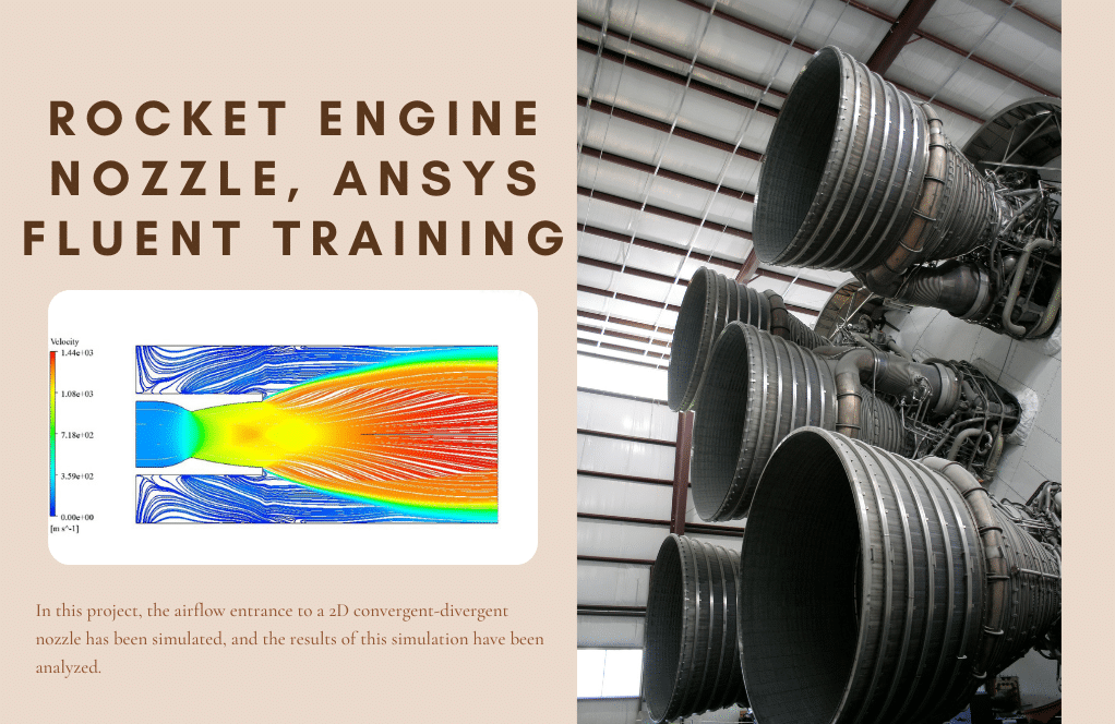
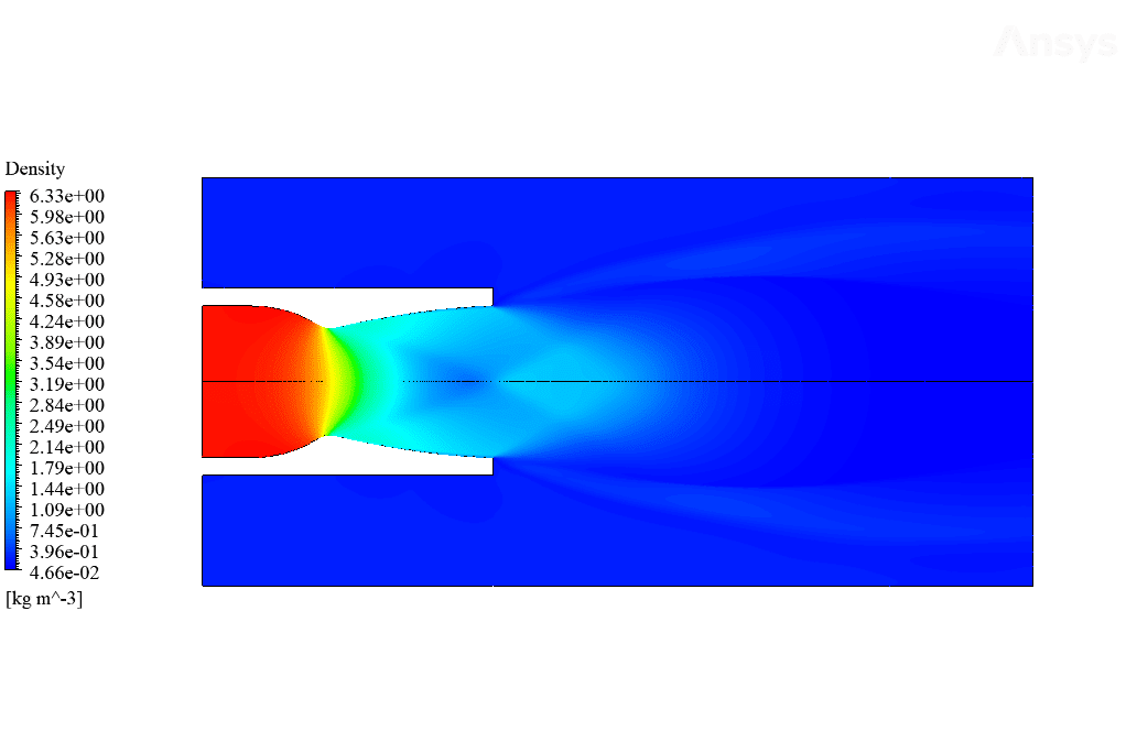
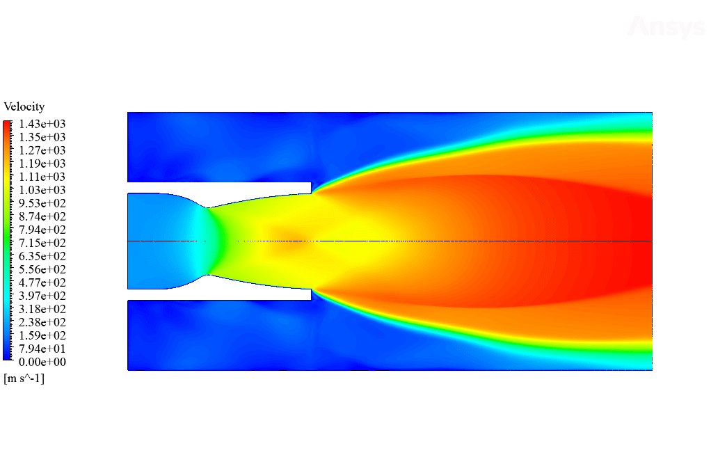
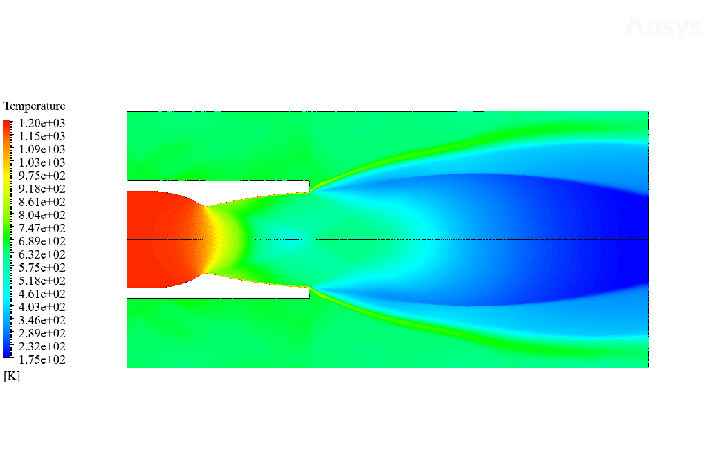
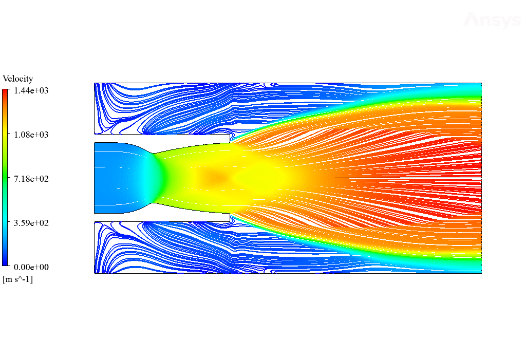
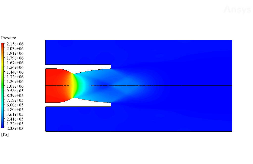
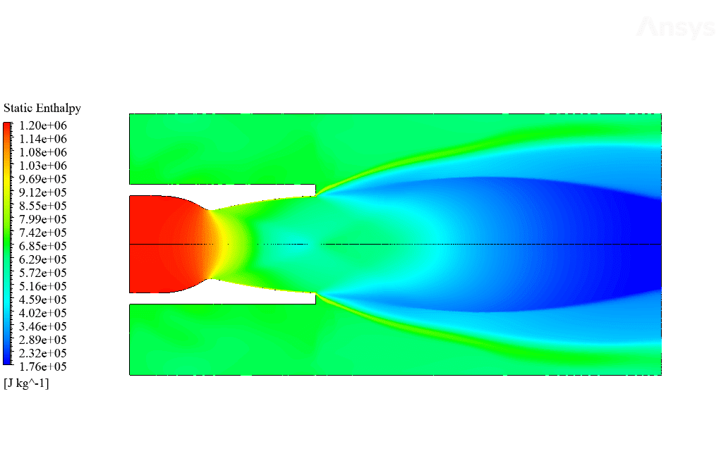
After calculation, 2D contours related to temperature, pressure, velocity, density, and enthalpy and 2D streamline are obtained.
The contours show that the gas flow accelerates significantly after passing through the throat area. This means that when the gas flow reaches the throat area, its speed increases and its pressure is broken due to the reduction of the cross-sectional area.
Laney Wisozk III –
This tutorial exceeded my expectations! Loved how thoroughly the rocket nozzle dynamics are explained, and the practical approach in the simulation is impressive. I felt confident following the steps and gained a deeper understanding of fluid behavior in rocket nozzles.
MR CFD Support –
Thank you for your review! We’re glad to know that our rocket engine nozzle CFD simulation training provided you with valuable insights and deepened your understanding of rocket nozzle fluid dynamics. It’s great to hear that our tutorial met your expectations and helped build your confidence in performing simulations. We appreciate your feedback!
Lorenzo Huel III –
The simulation visuals are incredible! Seeing the gas accelerate through the nozzle’s throat area and watching the pressure and velocity changes were captivating. It really helps to understand the mechanics of a rocket nozzle.
MR CFD Support –
Thank you for your positive feedback! We’re glad to hear that the visuals in the simulation helped you to understand the complex dynamics within a rocket engine nozzle. If you have any other observations or queries, feel free to reach out!
Celestine Runolfsdottir –
Is this training material suitable for someone who is new to rocket engine nozzle design and simulation?
MR CFD Support –
Yes, this training material is designed to guide users through the process of simulating a rocket engine nozzle in ANSYS Fluent. It covers the essentials and is beneficial for both beginners and those looking to reinforce their knowledge in this area.
Roma Weissnat –
The images and data visuals provided truly helped me to understand how the gas flow dynamics work within the rocket nozzle. The explanation of the acceleration of gases through the throat area was particularly enlightening. Top-notch simulation training.
MR CFD Support –
Thank you for your positive feedback! It’s fantastic to hear that our visual aids and detailed explanation of the flow dynamics were helpful for your understanding. We’re committed to providing high-quality simulation training and appreciate your recognition of our efforts.
Emily Mitchell –
This training helped me understand the complexities of rocket nozzle design. I now have a better grip on how nozzle shape influences exhaust velocity and engine efficiency. Do you provide more advanced courses that delve into combustion modeling within the nozzle?
MR CFD Support –
We’re thrilled to hear that you’ve gained a deeper understanding of rocket engine nozzle design through our training. Yes, we do offer advanced courses that further explore combustion modeling within the nozzle. These advanced modules feature comprehensive lessons on the principles of combustion, fuel and oxidizer mixing, ignition sequences, and detailed CFD analysis. If you’re interested in expanding your expertise, please take a look at our course listings for more information on advanced combustion modeling courses.
Margarette Haley –
The Rocket Engine Nozzle CFD Simulation training material has expanded my understanding of nozzle physics dramatically. The clear visuals of the temperature and pressure contours really demonstrated the flow behaviors perfectly!
MR CFD Support –
We are so thrilled to hear that our Rocket Engine Nozzle CFD Simulation training was helpful for you! Understanding the complexities of gas dynamics in rocket nozzles can indeed be transformative. We appreciate you taking the time to share your positive experience and hope our other training materials prove just as beneficial. Thank you for choosing MR CFD for your learning journey!
Ms. Lauretta Runte –
The explanation of the rocket engine nozzle simulation is quite comprehensive. Thanks for the amazing work!
MR CFD Support –
We appreciate your kind words! It’s fantastic to hear that our rocket engine nozzle simulation has met your expectations. Thank you for acknowledging the effort and detail we put into our training materials. If you ever have further questions or need additional support, feel free to reach out. Your satisfaction is our top priority!
Millie Senger –
I used the tutorial for the rocket engine nozzle CFD simulation, and the training was detailed and thorough. The explanations made it easy to understand the complex physics of thermo-fluid dynamics in rocket nozzles.
MR CFD Support –
Thank you for your positive feedback! We’re glad our training material was helpful and provided a clear understanding of the subject. If you have further questions or need assistance with other simulations, feel free to reach out.
Jacklyn Quitzon –
The training for the rocket engine nozzle CFD simulation sounds fascinating. What specific learning outcomes can I expect from this course?
MR CFD Support –
The learning outcomes from the rocket engine nozzle CFD simulation training include understanding the physics behind nozzle throat dynamics, becoming proficient in handling boundary condition setups for compressible flows in ANSYS Fluent, setting up and solving nozzle flow problems, interpreting simulation results such as temperature, pressure, velocity profiles, learning about shockwaves and expansion fans in nozzles, and gaining practical experience in meshing complex geometries in ANSYS Meshing. By completing the training, users should be able to conduct similar simulations independently.
Miss Lola Botsford –
Incredible results! The gradients captured in the gas flow transitioning from subsonic to supersonic were represented with remarkable clarity in the contours. The density-based solver seems like the right choice for such a complex flow!
MR CFD Support –
Thank you for your positive feedback! We’re delighted to hear that the clarity of the flow simulation in the rocket engine nozzle met your expectations. Our goal is to deliver comprehensive training that accurately demonstrates the physics of high-speed flows. If you have further interests or need assistance with other simulations, please feel free to reach out. Cheers to your success!
Dr. Joy Cremin DVM –
The training course has incredibly detailed and effective information on simulating a rocket engine nozzle. The step-by-step guidance made it easy to follow and understand the process from setting boundary conditions to interpreting the results.
MR CFD Support –
We sincerely appreciate your positive review and are pleased to know that our Rocket Engine Nozzle CFD Simulation training content has been valuable to you. It’s great to hear that the steps provided were clear and instructive. Thank you for choosing our training, and we look forward to continuing to support your learning journey in CFD with ANSYS Fluent.
Dr. Ludie Wehner –
The training content provided for the Rocket Engine Nozzle CFD simulation seems comprehensive. The complex physics involving supersonic flows and variance in cross-sectional areas of the rocket engine nozzle were well elaborated, and the training seemed geared towards revealing the relationships between temperature, pressure, density, and velocity in high-speed flows within the nozzle. A good understanding of these principles is crucial for anyone looking to enter the field of rocket propulsion or high-speed aerodynamics. The detailing of internal flow simulation using ANSYS Fluent is excellent preparation for practical applications. Thank you for a thorough course that bridges the gap between theory and real-world simulations.
MR CFD Support –
Thank you for your positive feedback on our Rocket Engine Nozzle CFD Simulation Training. We are dedicated to providing a detailed and practical understanding of rocket nozzle dynamics and are delighted to hear that you appreciate the thoroughness of our course materials. Stay tuned for more advanced simulations that continue building your expertise in the field of computational fluid dynamics (CFD) and aerospace propulsion.