Impeller of an Electrical Motor, Airflow Analysis
$120.00 Student Discount
- The problem numerically simulates the Impeller of an Electrical Motor using ANSYS Fluent software.
- We design the 3-D model by the Design Modeler software.
- We Mesh the model by ANSYS Meshing software, and the element number equals 1786708.
- We use the Frame Motion method to define the rotation of the impeller.
To Order Your Project or benefit from a CFD consultation, contact our experts via email ([email protected]), online support tab, or WhatsApp at +44 7443 197273.
There are some Free Products to check our service quality.
If you want the training video in another language instead of English, ask it via [email protected] after you buy the product.
Description
Impeller of an Electrical Motor, Airflow Analysis, ANSYS Fluent CFD Simulation Tutorial
This simulation is about the impeller of an electrical motor via ANSYS Fluent software. We perform this CFD project and investigate it by CFD analysis.
Turbomachines, also known as fluid machines, are widely used in the industry. Therefore, studying their behavior in the fluid environment around them is imperative. Turbomachines are divided into two general categories.
The first group transfers energy to the fluid, and the second group works and takes energy from the fluid, transferring it to the system in various forms. The first group’s examples are fans and compressors, and wind and water turbines can be mentioned as the second category.
Electric motors impeller is also a type of turbomachine that falls into the first category. Investigating the movement of such motors’ blades in the fluid flow surrounding them can help analyze their behavior and ultimately improve the design and selection of the material used in such blades.
In this project, the airflow passing over an impeller is investigated. The airflow enters the computational domain at 80m/s, and the impeller rotates at 1000rpm.
The geometry of the present model is drawn by Design Modeler software. The model is then meshed by ANSYS Meshing software. The model mesh is unstructured, and 1786708 cells have been created.
Impeller Method
In this simulation, the MRF (Frame Motion) option has been activated to model the rotation of the impeller. It is assumed that the fluid around the impeller blades is rotating instead of the impeller blades.
The rotational velocity of this fluid is equal to the rotational velocity of the turbine. To do this, the MRF tool is used in Cell Zone Conditions.
Impeller Conclusion
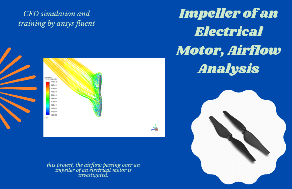
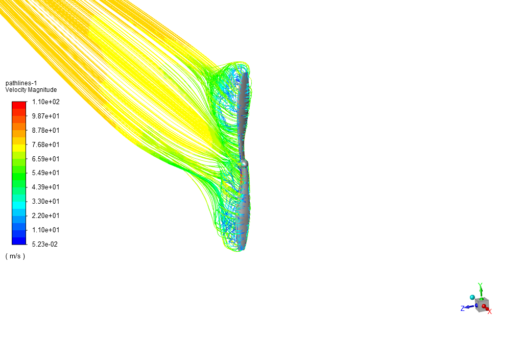
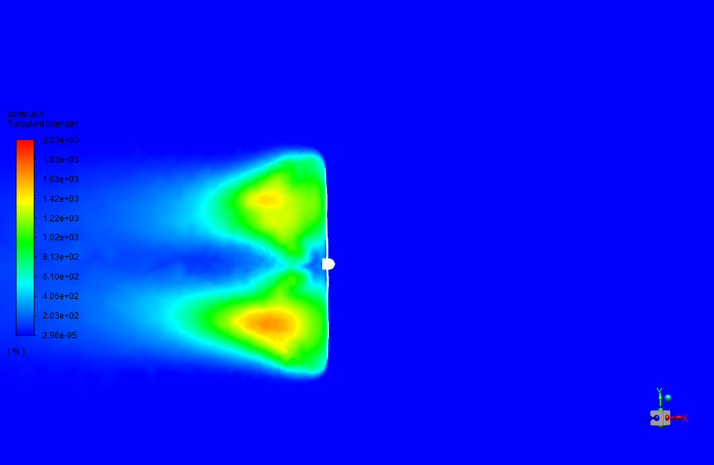
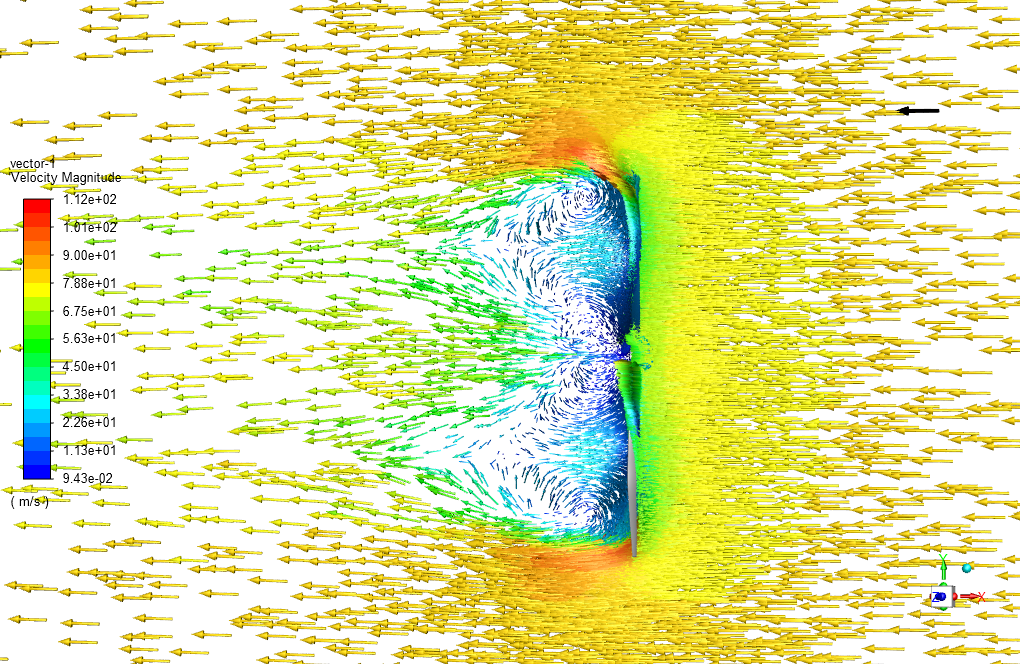
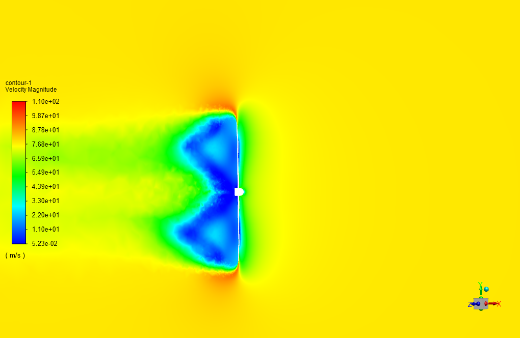
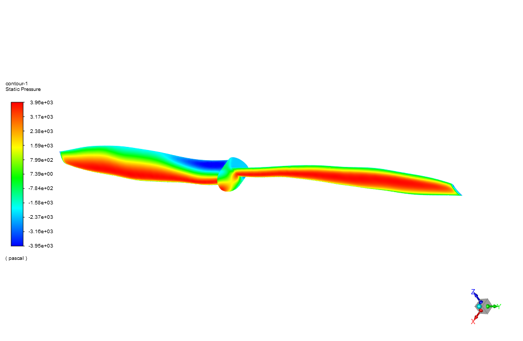
After simulation, the contours of pressure, velocity, and temperature are obtained. Also, pathlines and velocity vectors around the blades are obtained. The pathlines clearly show the rotational motion around the propeller blades.
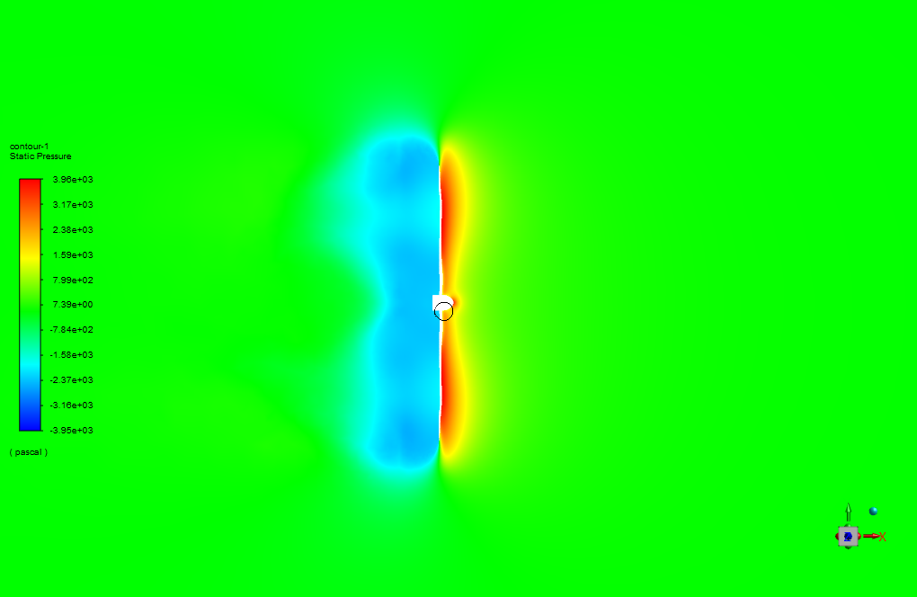
The pressure contour shows that the pressure is higher in the front part of the propeller because it is in contact with the airflow, and behind the propeller, a large pressure drop appears.
The velocity contour also shows that the velocity increases radially, and the maximum velocity appears around the tips of the blades. This indicates the rotational movement of this propeller.


Julie Schultz –
I was amazed by the level of detail in the airflow analysis around the electric motor’s impeller. The insights into how the pressure varies on the propeller and how the velocity increases radially were particularly remarkable.
MR CFD Support –
Thank you for your kind words! We’re thrilled to hear that you found the analysis detailed and informative. It’s always our goal to provide insightful and useful information that could aid in understanding complex fluid behaviors. We appreciate your feedback and are glad you found the results regarding pressure variation and radial velocity increase around the impeller’s blades to be remarkable.
Coy Huel –
Watching the tutorial, I was amazed by how detailed it is! As a visual learner, seeing the airflow pathlines around the blades and understanding the velocity changes truly enhanced my grasp on turbomachine dynamics.
MR CFD Support –
Thank you for your positive feedback! We’re thrilled to hear that our tutorial was able to cater to your learning style and that you found the visualizations, especially the pathlines and velocity changes around the blades, informative and helpful in understanding turbomachinery dynamics. We strive to provide detailed and instructive simulations to aid our customers, and your comment reaffirms our efforts. If there’s any other way we can assist in your learning journey, please let us know!
Nova Sporer –
I found the results regarding the increase in velocity around the impeller tips particularly fascinating. It’s impressive how precisely the simulation predicted the rotational effects and the corresponding radial velocity increase.
MR CFD Support –
Thank you for your positive feedback! We’re glad to hear that our simulation met your expectations and provided valuable insights. The precise prediction of flow characteristics around turbomachines like this impeller is essential for optimizing performance, and we’re happy to have contributed to your understanding with our analysis.
Marco Nolan –
Thank you for providing such a comprehensive simulation of the impeller in an electrical motor! I found the visualization of the flow fields particularly informative for understanding how pressure and velocity changes throughout the system.
MR CFD Support –
Thank you for your positive feedback! We are delighted to know that you found our impeller simulation informative and helpful for visualizing the flow dynamics in an electrical motor. Your appreciation encourages us to keep delivering high-quality CFD simulations. If you have any more questions or need further assistance, feel free to reach out!
Prof. Irwin Rodriguez DVM –
I am very impressed with how the simulation captures the pressure and velocity changes around the impeller blades. The level of detail in the analysis helps in understanding the airflow behavior, which is critical for improving the design. Fabulous work!
MR CFD Support –
Thank you for your positive feedback! We’re glad to hear that our simulation was able to provide you with detailed insights into the airflow behavior around the impeller blades, and that you found it helpful for design improvement purposes. It’s always our goal to assist in enhancing understanding and driving innovation.
Mustafa Hegmann PhD –
I am really impressed by how effectively the impeller simulation predicts the airflow and pressure distribution. Will this simulation also help in determining the best material for the impeller blades based on the findings?
MR CFD Support –
Thank you for the compliment on the impeller simulation. While the primary objective of the simulation is to analyze the airflow and pressure distribution around the impeller, the results obtained from the stress and strain on the impeller blades due to the fluid forces can certainly guide the material selection for the blades to ensure they withstand operating conditions effectively.