FSI Analysis of Airflow around an Airfoil Vibration
$270.00 Student Discount
- The problem numerically simulates the airflow around an airfoil using ANSYS Fluent software.
- This project is performed by the fluid-structure interaction (FSI) method.
- We design the 2-D model with the Design Modeler software.
- We Mesh the model with ANSYS Meshing software, and the element number equals 56220.
- We perform this simulation as unsteady (Transient).
- We use the Dynamic Mesh method to consider grid changes over time.
- We apply the System Coupling to communicate between Fluent and Transient Structural software.
- We use the Density-based solver to consider compressible flow.
- We use a UDF to determine variable velocity and attack angle.
To Order Your Project or benefit from a CFD consultation, contact our experts via email ([email protected]), online support tab, or WhatsApp at +44 7443 197273.
There are some Free Products to check our service quality.
If you want the training video in another language instead of English, ask it via [email protected] after you buy the product.
Description
FSI Analysis of Airflow around an Airfoil CFD Simulation, ANSYS Fluent Training
The present problem is FSI Analysis of Airflow around an Airfoil using the Fluid Solid Interaction (FSI) method in ANSYS Fluent software.
In this simulation, a circular computational domain of airflow is designed; So that an airfoil is located in this area. Since this airfoil is moving at a considerable speed, the airflow collides with its body and exerts a force on it.
In this model, a circular hole inside the airfoil is distinguished from defining the boundary of the inner surface around this circle as fixed support. This boundary or surface is constantly affected by the interaction with the fluid flow and does not change position or deform.
However, the two sides of the airfoil are displaced due to the collision of the fluid flow with the airfoil body; therefore, these boundaries must be defined as displacement.
To do this, we should define a data transfer from the model wall in fluent software to the same model wall in transient structural software as Force. This means that fluid flow around the airfoil wall strikes the wall and exerts a force on it.
Also, we should define a data transfer from the model wall in transient structural software to the same model wall in Fluent software as displacement. This means that the wall changes the flow of fluid around it.
In the present modeling, a circular computational domain is considered to define the airflow, the circumference of which is defined as the inlet boundary of the airflow.
We design the present model in three dimensions using Design Modeler software. The model includes a circular computational domain with a diameter of 4.8 m and an airfoil inside this area. This computational area has only the inlet airflow, and the lateral faces of this area have a symmetry condition.
We carry out the meshing of the model using ANSYS Meshing software, and the mesh type is unstructured. The element number is 56220.
FSI Methodology
As a result, we can say that a two-way confrontation occurs between the fluid and the solid. Therefore, we use the FSI method in the ANSYS Workbench software environment.
When using the FSI method, due to the change in the structure of the fluid flow mesh around the geometric model, it is necessary to define a Dynamic Mesh; Because the Dynamic Mesh technique allows changing the mesh structure of the model in a time-dependent manner.
In determining dynamic mesh methods, smoothing and remeshing methods have been used. We should use system coupling in ANSYS Workbench software to define two-way fluid-solid interaction.
To do this, you must first define the model in each of the Fluent and Transient Structural software and then couple the process of solving them with this system coupling, considering that the geometry is the same in both fluid and solid design modes.
We should also establish a coupling between the geometry of these two software. This means that the instantaneous change in the structure of the mesh is due to coupling with solid analysis.
Finally, to make a connection or coupling between fluid and solid and to define their effect on each other, data transfer must be defined; In this way, the results of these two solutions in the two software are transferred to each other.
Therefore, we define two data transfers in the system coupling section; Thus, we must define this data transfer for a specific area or boundary from a source to a target.
Therefore, the velocity inlet boundary condition is used at this border, So that the airflow velocity and the airflow directions are variable as a function of time. Being variable in the airflow direction means that the airfoil’s angle of attack varies with time.
Therefore, the UDF was used to determine the variable velocity and to determine the variable attack angle.
Due to the main nature of the model based on the use of dynamic mesh, we should apply a transient solver for the simulation process. The present model performs the simulation process in 0.32 seconds with a time step size of 0.0005 seconds.
Since the simulation process is performed in both fluid and solid software, we define the same time for both software. We perform a density-based solver since the air velocity is very high. The simulation is also Transient.
FSI Analysis of Airflow around an Airfoil Conclusion
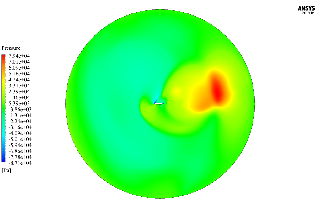
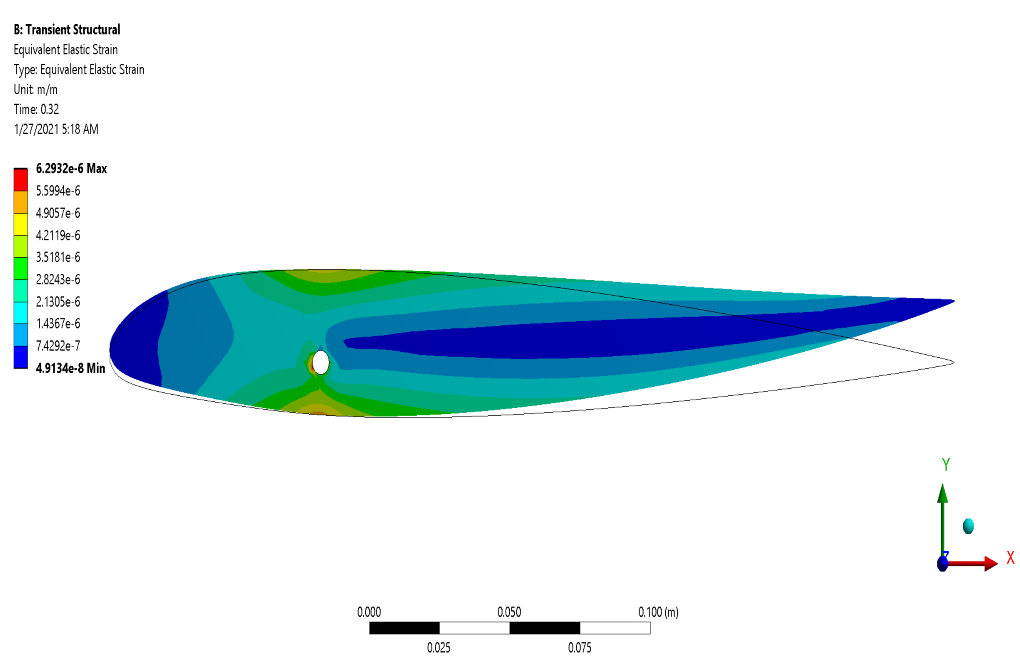
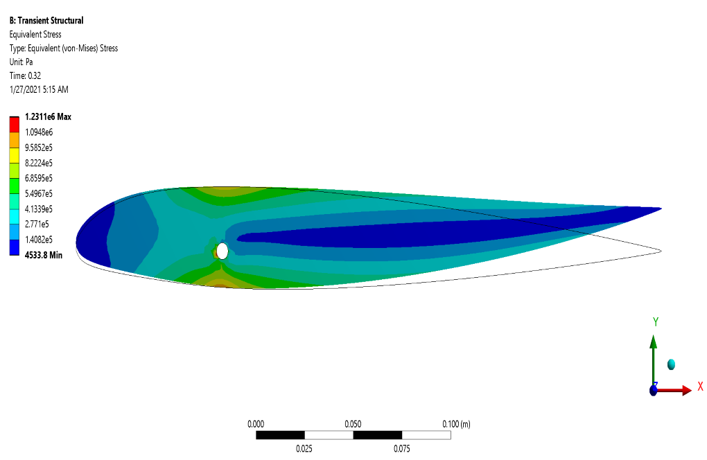
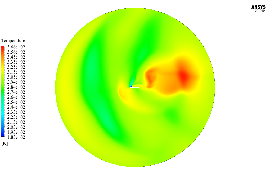
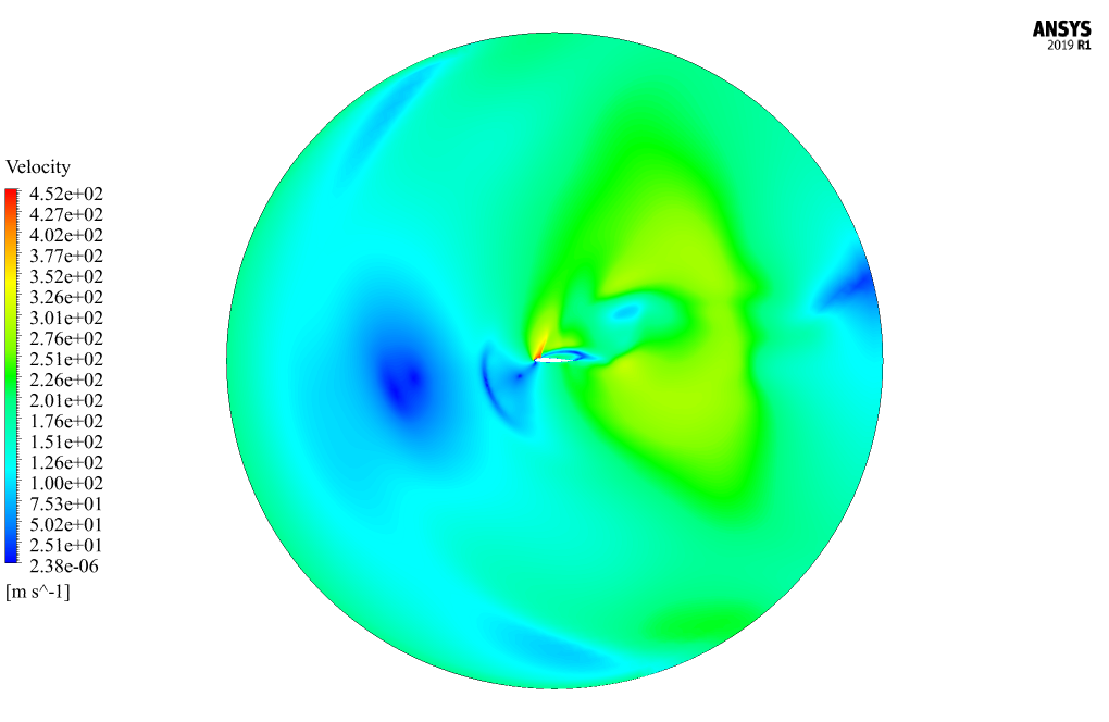
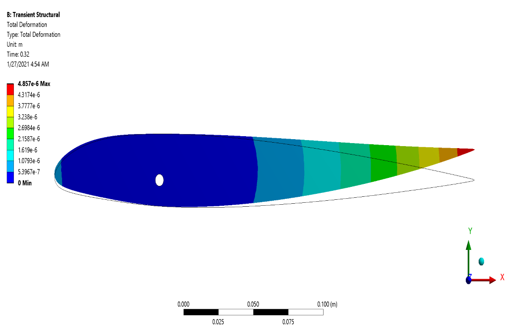
After the solution process, we obtain the results in both Fluent and Transient Structural software. In transient structural software, we represent deformation, strain, and stress contours on the outer surface of the airfoil.
These contours correspond to the simulation’s final second (0.32 s). In fluent software, we show two-dimensional contours related to velocity, pressure, and temperature on the symmetrical surface of the computational area around the mentioned airfoil.
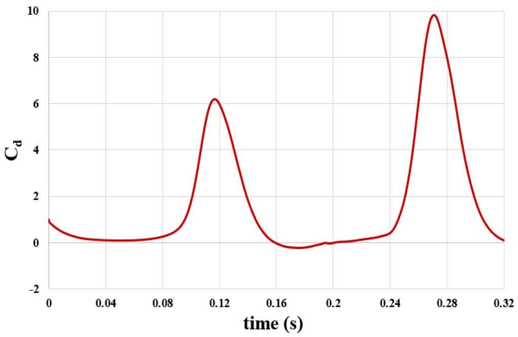
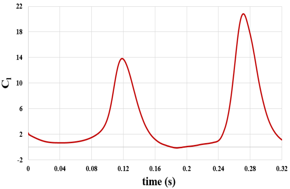
These contours also correspond to the simulation’s final second (0.32 s). Also, we present the diagram of changes in drag coefficient and lift coefficient applied on airfoil over time in 0.32 s.
Prof. Xzavier McLaughlin –
I noticed that the simulation uses the k-omega SST turbulence model. Can you explain why this model was chosen over others like the k-epsilon or Spalart-Allmaras models?
MR CFD Support –
The k-omega SST turbulence model was chosen for this simulation due to its ability to accurately capture the boundary layer separation, which is a critical aspect of airflow around an airfoil. This model combines the best features of both the original k-omega and the k-epsilon models, making it a good choice for this simulation.
Mr. Jeffry Kris PhD –
How does this simulation model the interaction between the airflow and the airfoil?
MR CFD Support –
This simulation models the interaction between the airflow and the airfoil using the no-slip condition at the airfoil surface. This means that the air velocity at the airfoil surface is assumed to be zero.
Cynthia Rippin –
What kind of post-processing options are available for analyzing the simulation results?
MR CFD Support –
The post-processing options include the visualization of pressure and velocity fields, as well as the calculation of lift and drag coefficients.