Rotary Cooling of an object with a Constant Heat Flux, ANSYS Fluent training
$100.00 Student Discount
The present problem simulates the heat transfer and rotary cooling of a wall under a constant heat flux of a model with a semi cylinder shape, using ANSYS Fluent software.
Click on Add To Cart and obtain the Geometry file, Mesh file, and a Comprehensive ANSYS Fluent Training Video.To Order Your Project or benefit from a CFD consultation, contact our experts via email ([email protected]), online support tab, or WhatsApp at +44 7443 197273.
There are some Free Products to check our service quality.
If you want the training video in another language instead of English, ask it via [email protected] after you buy the product.
Description
Rotary Cooling Project Description
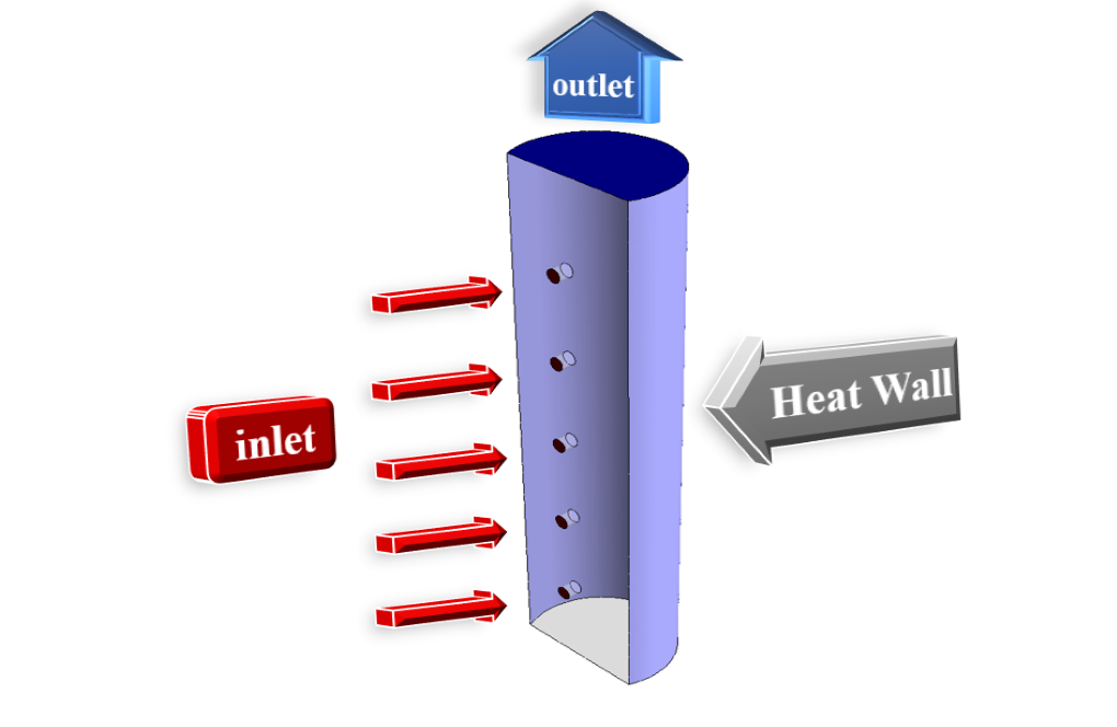
The present problem simulates the heat transfer and cooling of a wall from a model with a semi-cylinder shape, using ANSYS Fluent software. The model rotates around a particular axis (model z-axis) at a speed equivalent to 400 rpm. Therefore, to define this rotational motion in the model, the frame motion technique with a rotational speed of 400 rpm has been used. The exterior sectional wall of the model under constant heat flux is equal to 1000 W.m-2, and on the outer surface of this sectional wall, there are five ducts for airflow.
Cooling airflow with a velocity of 29.215 ms-1 (assuming Reynolds 10000 for the inlet airflow to the model) and a temperature of 300 K enter the model through five inlet ducts the outlet section located at the top of the model at equivalent pressure Atmospheric pressure is released.
Geometry & Mesh
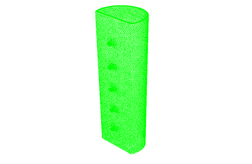
The present model is designed in three dimensions using Design Modeler software. The model consists of an semi-cylinder with a diameter of 50 mm and a height of 200 mm, on the lateral surface of which are five air inlets for a diameter of 5 mm.
We carry out the meshing of the model using ANSYS Meshing software, and the mesh type is unstructured. The element number is 679558. The following figure shows the mesh.
Rotary Cooling CFD Simulation
We consider several assumptions to simulate the present model:
- We perform a pressure-based solver.
- The simulation is steady.
- The gravity effect on the fluid is Ignored.
The following table represents a summary of the defining steps of the problem and its solution:
| Models | ||
| Viscous | k-omega | |
| k-omega model | SST | |
| Energy | On | |
| Boundary conditions | ||
| Inlet | Velocity Inlet | |
| velocity magnitude | 29.215 m.s-1 | |
| temperature | 300 K | |
| Outlet | Pressure Outlet | |
| gauge pressure | 0 pascal | |
| Heat Wall | Wall | |
| wall motion | stationary wall | |
| heat flux | 1000 W.m-2 | |
| Wall | Wall | |
| wall motion | stationary wall | |
| heat flux | 0 W.m-2 | |
| Methods | ||
| Pressure-Velocity Coupling | SIMPLE | |
| pressure | second order | |
| momentum | second order upwind | |
| turbulent kinetic energy | first order upwind | |
| specific dissipation rate | first order upwind | |
| energy | second order upwind | |
| Initialization | ||
| Initialization methods | Standard | |
| gauge pressure | 0 pascal | |
| x-velocity & y-velocity | 0 m.s-1 | |
| z-velocity | -29.215 m.s-1 | |
| temperature | 300 K | |
Results & Discussions
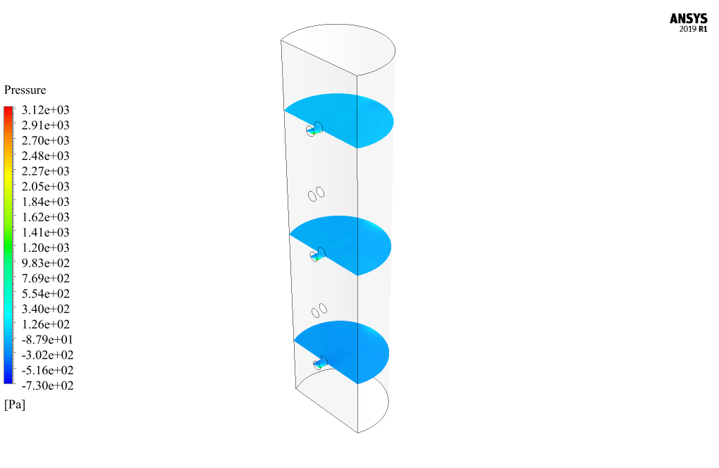
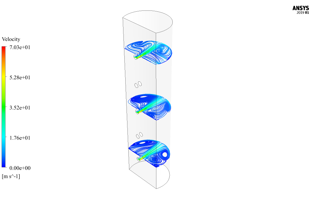
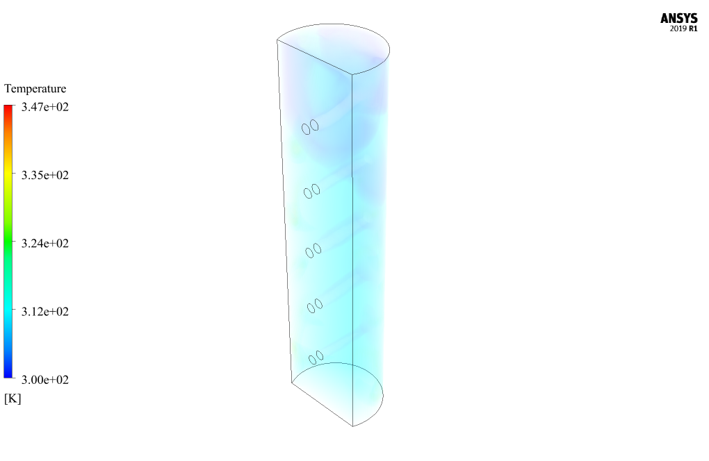
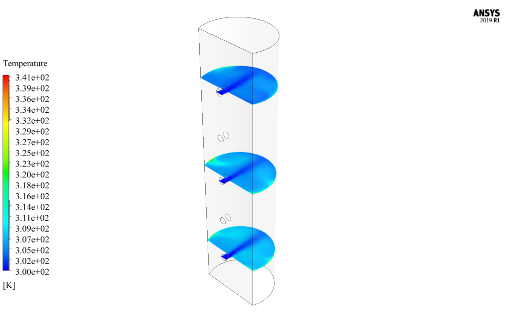
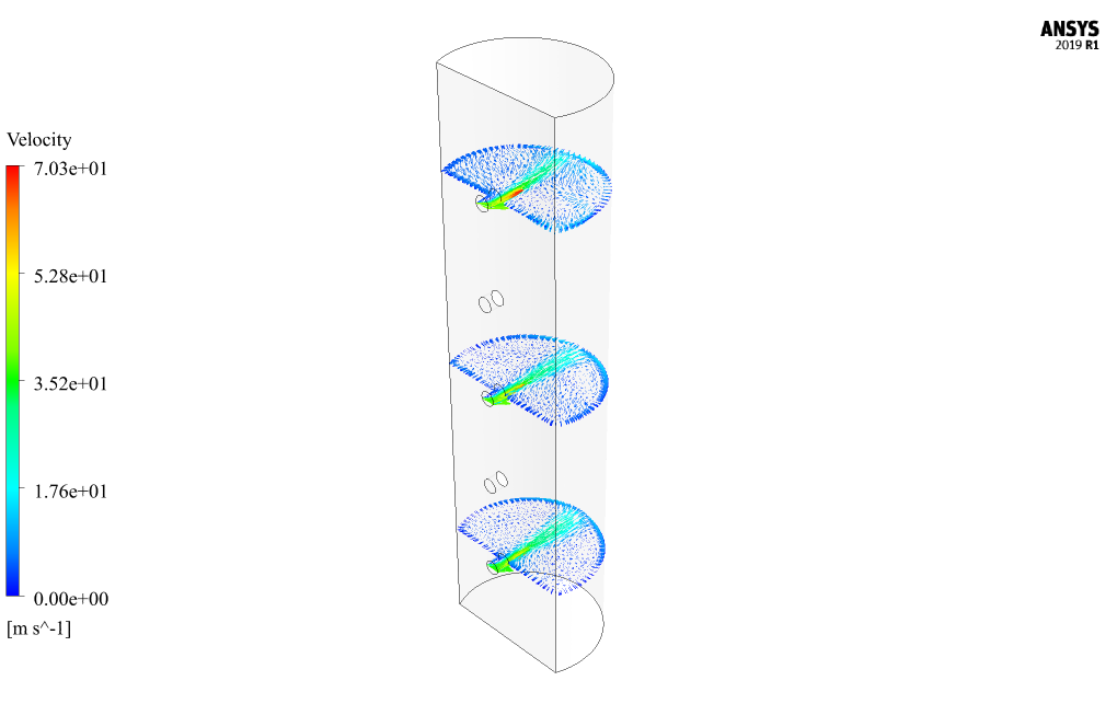
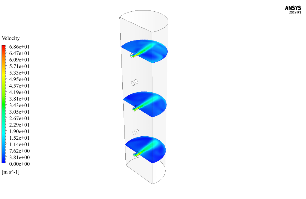
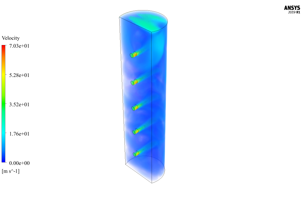
At the end of the solution process, two-dimensional and three-dimensional contours related to pressure, speed, and temperature are obtained. Also, two-dimensional velocity vectors and two-dimensional flow lines have been obtained in different sections of the model. Two-dimensional sections are created on pages parallel to the X-Z plane of the model; So that they include the first (lowest), third (middle), and fifth (highest) inputs of the model. The contours show that the temperature is high near the heat flux wall, and when the airflow from the inlets hits this heat flux wall at high speed, it reduces the temperature.
The graph of changes in the amount of static pressure (relative pressure) on the model’s heat flux wall at different cross-sections (including the first, third, and fifth inputs) is obtained. These figures show that the highest pressure is created in the central part of this wall because the airflow hits it directly at high speed.


Garth Schaden –
Can the simulation handle transient analysis?
MR CFD Support –
Absolutely! The simulation can perform transient analysis to study the time-dependent behavior of the heat transfer and air flow in the system.
Prof. Pedro Berge –
I found the initialization settings particularly insightful. Could you clarify if initializing the z-velocity to -29.215 m.s-1 takes into account the rotational motion of the semi-cylinder or is it solely for the airflow within the ducts?
MR CFD Support –
The initialization setting for the z-velocity at -29.215 m.s-1 is specifically for the airflow being introduced into the model through the ducts. This value is set to match the inlet condition of the cooling airflow. The rotational motion of the semi-cylinder is accounted for separately in the frame motion technique which sets the rotational speed of the model to 400 rpm. The negative sign indicates the direction of the airflow relative to the coordinate system defined in the simulation.
Scot D’Amore IV –
I found the description of the rotary cooling project quite comprehensive. The detailed explanation of boundary conditions and the solver settings gave me a deep understanding of the simulation process. It’s fascinating to see how the heat transfer is affected by the wall rotation in conjunction with the airflow through the ducts. I appreciate the effort taken to simulate and present the velocity vectors and temperature contours, making it easier to envision the cooling mechanism at work.
MR CFD Support –
Thank you so much for your thoughtful review! We’re delighted to hear that the detailed explanation of the simulation helped you to understand the complex interplay between the wall rotation and the cooling airflow. We always strive to present our results in a way that is both informative and visual to help our customers get a comprehensive understanding of the simulation process. Your feedback motivates us to keep providing high-quality learning products
Amely Leannon –
The tutorial on Rotary Cooling using ANSYS Fluent was exceptional! The explanations, especially on how to set up the rotational motion and the details concerning boundary conditions were clear and easy to follow. The included figures and graphs provided excellent visual support to the theoretical aspects. My understanding of heat transfer phenomena in a dynamic case like this has improved significantly.
MR CFD Support –
We’re thrilled to hear you found our tutorial on Rotary Cooling in ANSYS Fluent so helpful! It’s great to know the clarity and detail of the explanations, along with the visual aids, enhanced your understanding of the heat transfer in rotary systems. Thank you for your positive feedback!
Mr. Frankie Jakubowski –
Really impressive analysis on the rotary cooling simulation! It’s not every day you see such clear results on air cooling efficiency over a constant heat flux surface with detailed airflow modeling.
MR CFD Support –
Thank you for your positive feedback. We’re pleased to know that our analysis on rotary cooling simulation met your expectations and provided clear insights. Your satisfaction with our detailed airflow modeling is much appreciated!
Alize Dooley –
I am amazed by the level of detail in the simulation of rotary cooling, but can you tell me if the gravity effect is considered in the simulation and how does it affect the results?
MR CFD Support –
The gravity effect has been ignored in this simulation. This is a common assumption in CFD analysis when the gravity effect is negligible compared to other forces in the system, such as when the force of the airflow and rotation are significantly more influential on the heat transfer process.
Katlyn Botsford IV –
This ANSYS Fluent rotary cooling training material seems comprehensive, but I’m wondering if the effects of rotation on the turbulence model have been taken into account?
MR CFD Support –
In this simulation, external rotational effects on the turbulence model are handled adequately by employing the k-omega SST turbulence model, which is compatible with rotating flows and can capture the effects of swirls and rotation-induced stresses. If there are any specific concerns or aspects you’d like to learn more about regarding how rotation influences the turbulence in this context, I would be happy to assist further!
Carey Ferry PhD –
Can the simulation model the effect of different semi-cylinder geometries?
MR CFD Support –
Yes, the simulation can model different semi-cylinder geometries. We can adjust the geometry based on your specific requirements.
Darion Mueller –
This course exactly meets my requirements. However, I’m curious, does it include a section on predicting the equipment lifespan and efficiency loss over time due to prolonged heat exposure and cooling cycles?
MR CFD Support –
Glad to hear that our course meets your needs! The focus of this training is primarily on the simulation of heat transfer and cooling, rather than on predicting equipment lifespan and efficiency loss over time. That said, with the knowledge gained from this simulation process, one may apply additional simulations or methodologies to predict equipment lifespan, although that would typically require more advanced analysis incorporating fatigue, material degradation, and possibly coupling with other simulation disciplines.
Alvina Herman –
The training material covers a comprehensive analysis, but I’m curious about the validation process. How does MR CFD ensure that the simulation accurately models the physical phenomena described in the project?
MR CFD Support –
In MR CFD simulations, we ensure accuracy and validation by comparing results with theoretical predictions, empirical data, or experimental results when available. We also conduct sensitivity analyses, mesh independence studies, and monitor convergence of results to establish confidence in the simulation outputs.
Prof. Joana Connelly PhD –
Can the simulation predict the air velocity distribution in the system?
MR CFD Support –
Yes, the simulation can predict the air velocity distribution in the system. This is important for understanding the air flow pattern and the cooling effectiveness.
Providenci McClure –
I’m amazed by how detailed this simulation is! The application of the rotating frame for the semi-cylinder and airflow cooling dynamics is very impressive.
MR CFD Support –
Thank you for your kind words! We do our best to create detailed and accurate simulations to help our users understand complex engineering concepts better. It’s wonderful to hear that you’re impressed with the work. If you have any further feedback or need additional information, feel free to reach out.
Virginia Klocko –
This course was really effective for understanding rotary cooling simulation. The connection between heat flux conditions and the impact of inlet flow velocity was particular insightful. Are future updates planned to include simulations with varying material properties, or different shapes other than the semi-cylinder?
MR CFD Support –
We appreciate your feedback on the Rotary Cooling of an object with a Constant Heat Flux tutorial. As of now, we do continually strive to improve and extend our training products, which may include simulations with varying material properties or different geometric configurations depending on the demands and interests of our users. Keep an eye out for announcements regarding new simulation tutorials.
Jailyn Emmerich Sr. –
I loved how detailed the simulation is! It includes various factors like wall motion and cooling airflow which must make the results very reliable.
MR CFD Support –
Thank you! We appreciate your positive feedback and are delighted to hear that you are satisfied with the thoroughness and reliability of the results from our rotary cooling simulation using ANSYS Fluent. If you have further questions or need assistance with similar simulations, feel free to reach out.
Miss Aracely Effertz III –
Fantastic training material from MR CFD! I learned so much about the particulars of setting up a cooling simulation with a rotating domain. The detailed instructions on how to account for constant heat flux and the strategy to model airflow cooling were spot for and easy to follow. Watching the temperature drop as the air moved across the surface in Fluent was satisfying and really cemented the concepts. Can’t wait to apply these techniques to my own projects!
MR CFD Support –
Thank you for your positive feedback! We are thrilled to hear that you found our training material on rotary cooling simulations to be detailed and helpful. It’s great to know that our instructions were clear and that you could practically see the concepts in action within ANSYS Fluent. We appreciate your enthusiasm and are excited to see how you leverage these techniques in your future work. If you have any questions or need further assistance, remember that our support team is always here to help!