Kaplan turbine CFD Simulation, ANSYS Fluent Training
$120.00 Student Discount
- The problem numerically simulates the Kaplan turbine using ANSYS Fluent software.
- We design the 3-D model with the Design Modeler software.
- We Mesh the model with ANSYS Meshing software, and the element number equals 919824.
- We use the Frame Motion (MRF) to define the rotational movement.
To Order Your Project or benefit from a CFD consultation, contact our experts via email ([email protected]), online support tab, or WhatsApp at +44 7443 197273.
There are some Free Products to check our service quality.
If you want the training video in another language instead of English, ask it via [email protected] after you buy the product.
Description
Kaplan turbine CFD Simulation by ANSYS Fluent Training
This simulation is about the Kaplan turbine via ANSYS Fluent software.
Turbomachines, also known as fluid machines, are widely used in the industry. Therefore, studying their behavior in a fluid environment is very important. Turbomachines are divided into two general categories.
The first group works by taking energy and transferring it to the fluid, and the second group, by doing work and taking energy from the fluid, transfers it to the system in various forms.
The first group’s examples are fans and compressors, and wind and water turbines can be mentioned as the second category. Kaplan turbines fall into the second category. Inward Flow Reactive Turbines are one of the most popular turbines used in the industry, using the concepts of Axial and Radial flows.
The inlet is a tube that rotates around the guide valves. The water enters the runner tangentially through the guide valves and becomes spiral by the runner propeller blades, which eventually causes the runner to rotate.
This project investigates the water flow passing over the Kaplan turbine. The Kaplan turbine rotates at 3300 rpm. The geometry of the present model is drawn by Design Modeler software.
The model is then meshed by ANSYS Meshing software. The model mesh is unstructured, and 919824 cells have been created.
Methodology
In this simulation, the MRF (Frame Motion) option has been activated to model the rotation of the turbine. In this simulation, the MRF (Frame Motion) option has been activated to model the rotation of the turbine.
It is assumed that the fluid around the turbine blades is rotating instead of the turbine blades. The rotational velocity of this fluid is equal to the rotational velocity of the turbine. To do this, the MRF tool is used in Cell Zone Conditions.
Conclusion
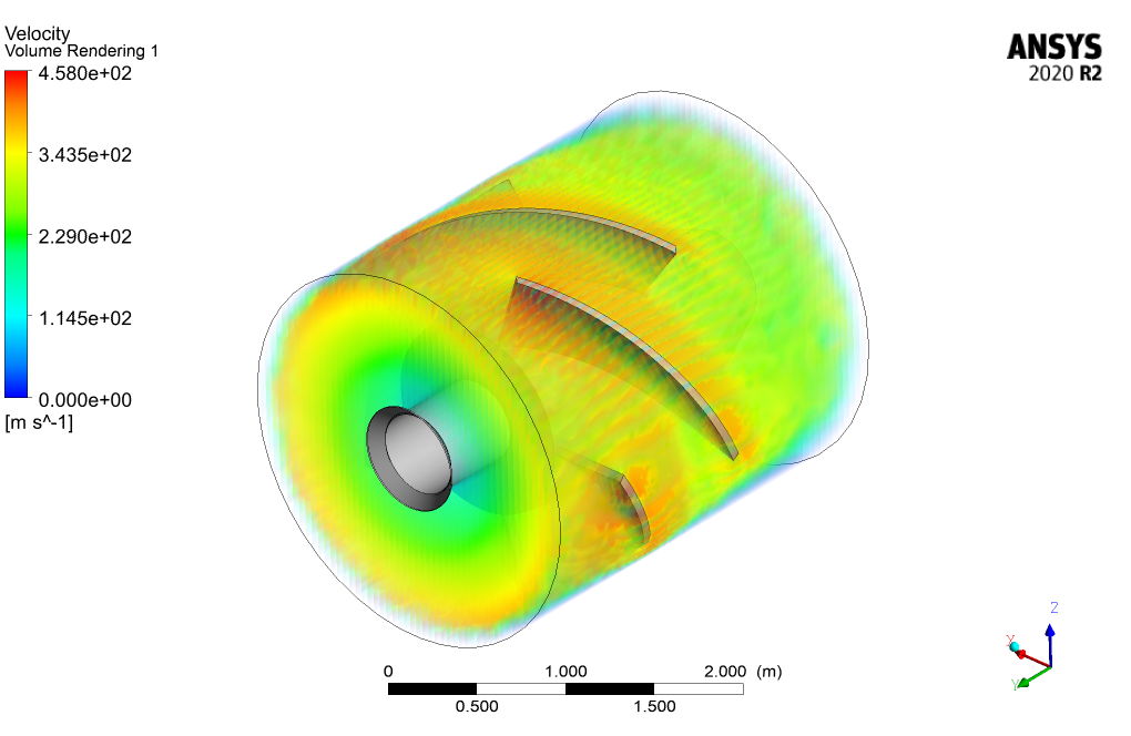
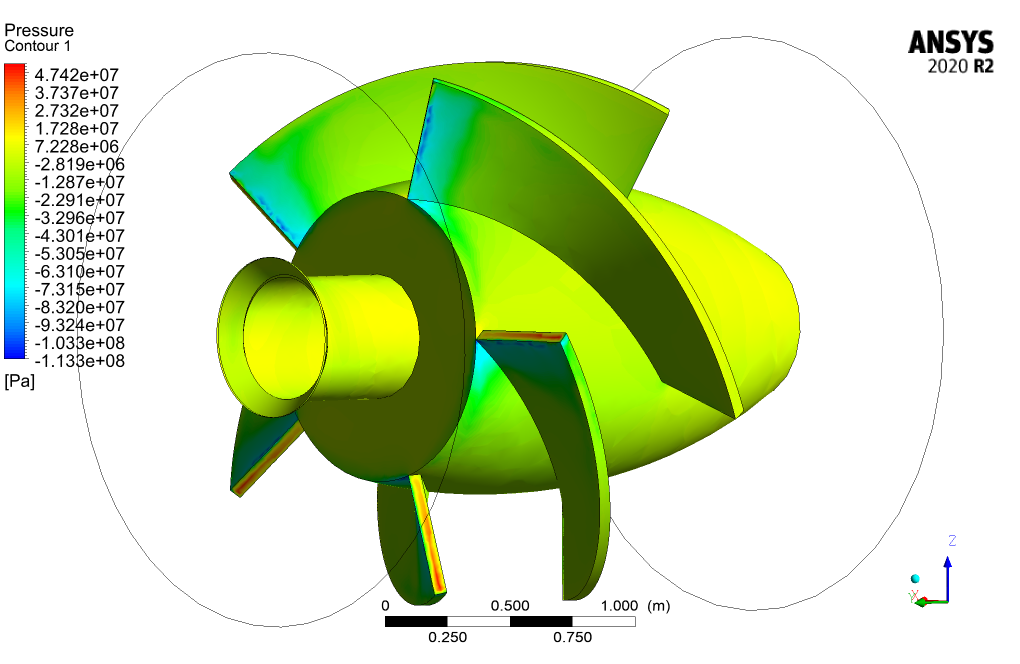
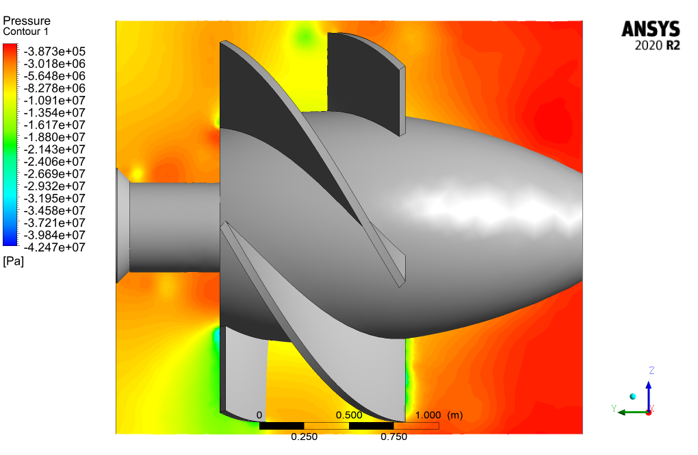
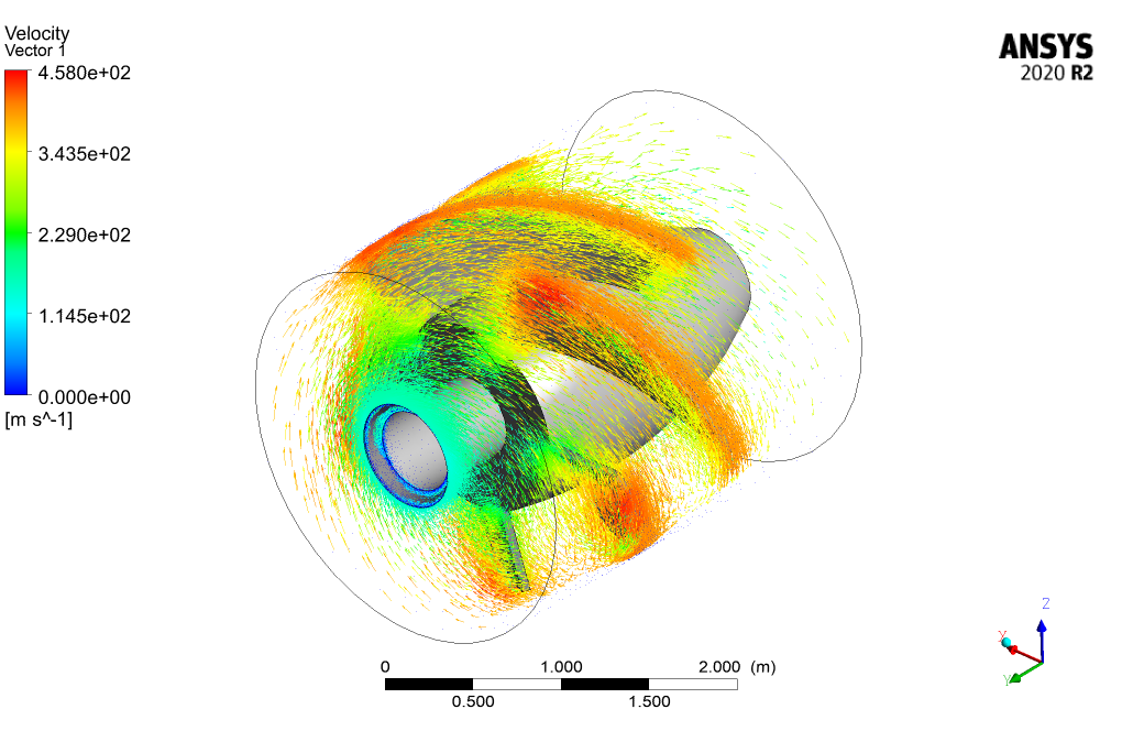
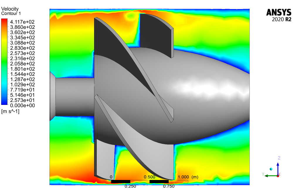
After simulation, 2D and 3D contours of pressure, velocity, and surface pressure are obtained. Also, the velocity vector of fluid around the turbine is obtained. Velocity vectors show the rotational motion of the fluid around the turbine blades.
As seen in the pressure contour for the turbine’s surface, some sections on the turbine blades are exposed to decreased pressure. These parts can potentially be where the cavitation can occur and should be studied and examined more carefully.


Ismael Walsh –
I’ve been really impressed with the Kaplan turbine CFD Simulation training provided by MR CFD. The usage of the MRF method to model turbine rotation was particularly insightful, and helped me understand the fluid dynamics around the turbine blades more vividly.
MR CFD Support –
We’re delighted to hear that you found the training insightful and helpful for understanding the fluid dynamics around the Kaplan turbine blades. Our goal is always to provide clear and thorough explanations to ensure a comprehensive learning experience. Thank you for taking the time to share your positive feedback!
Mr. Gustave Dare –
The results of the Kaplan turbine simulation look thorough. The engagement of the MRF tool seems key to analyzing the rotational flow.
MR CFD Support –
Thank you for your review! Indeed, utilizing the MRF tool greatly enhances our analysis of the Kaplan turbine’s performance in various fluid dynamic conditions. We’re glad you appreciate the detail in our simulation.
Mr. Sigrid Kerluke DDS –
I was impressed with the detailed analysis of the Kaplan turbine simulation in ANSYS Fluent. The 3D contours of pressure and velocity really helped to visualize the complex flow. Excellent training material for understanding turbomachinery!
MR CFD Support –
Thank you for your positive feedback! We are thrilled to hear that our Kaplan turbine CFD Simulation training has helped you visualize and understand the complexities of turbomachinery flow. Your satisfaction with our products is our top priority!
Imani Nitzsche –
I’m really impressed by the comprehensive nature of this simulation. The focus on rotational fluid dynamics and how they interact with the turbine blades is fascinating, especially how it explains potential cavitation locations.
MR CFD Support –
Thank you so much for your positive feedback! We’re glad to hear that the Kaplan turbine simulation provided you with valuable insights into fluid dynamics and potential cavitation. Your appreciation truly motivates us to continue delivering quality educational content.
Miss Jessyca Crist Jr. –
I have always been fascinated by the Kaplan turbine simulations and this training seems comprehensive. The final rendered images and fluid dynamic analysis really helped me understand the complex motion within the turbine. Great work!
MR CFD Support –
Thank you for your kind feedback! We’re delighted to hear that our Kaplan turbine CFD simulation training was able to enhance your understanding of fluid dynamics within turbines. It’s our goal to provide comprehensive and insightful analyses through our visualizations, and it’s great to know we’ve achieved that with you. If you have any more questions or need further information on similar topics, feel free to reach out to us.
Rashad Ziemann –
I was really impressed with the Kaplan turbine simulation training! It was well-structured and the step-by-step training made it easy to understand the complexities of turbomachine simulations in ANSYS Fluent.
MR CFD Support –
Thank you for your positive feedback on our Kaplan turbine simulation training! We’re thrilled to hear that the training met your expectations and helped clarify the complex aspects of running turbomachine simulations. We aim to provide clear and comprehensive resources to our customers, and your review validates our efforts. Should you have any further questions or need assistance with other simulations, please feel free to reach out. We appreciate your support!
Mrs. Ruby Hermiston Jr. –
I found the simulation of the Kaplan turbine fascinating. The level of detail considered in velocity and pressure changes helps in understanding potential cavitation spots on the blades, which can greatly aid in turbine design and maintenance. It’s impressive how comprehensive the analysis is with the use of MRF. Great learning material – helps with both the theory and practical applications in turbomachinery!
MR CFD Support –
We’re delighted to hear you found the Kaplan turbine simulation helpful! Understanding the complexities of turbomachinery like potential cavitation is crucial for design and maintenance, and it’s our goal to provide a comprehensive educational experience. We appreciate your recognition of the thoroughness and practical applications covered in our learning materials. Thank you for your positive feedback!
Burley Powlowski –
I found the training very informative, especially the use of MRF for modeling the turbine rotation. Great content and clear presentation!
MR CFD Support –
Thank you for your positive feedback! We’re thrilled to hear that you found the Kaplan turbine simulation training to be informative and that the content was presented clearly. Your satisfaction is our top priority. We hope you continue to enjoy our learning products and find them useful for your simulations.
Emilie Moen –
The Kaplan turbine CFD simulation appears very thorough. Can you share what the most significant insights were learned from the pressure and cavitation zones on the turbine blades?
MR CFD Support –
In this simulation, we identified that certain sections on the turbine blades have areas of decreased pressure, which are crucial since they indicate potential cavitation zones. Careful analysis of these zones is necessary for turbine design and operation optimization to reduce the risk of damage from cavitation erosion or efficiency loss due to bubble formation and collapse.
Kathlyn Turcotte –
I purchased the Kaplan turbine CFD simulation training and found it incredibly detailed. The methodology was clearly explained, and the use of MRF to model the turbine’s rotation was ingenious. The in-depth analysis of the pressure contour on the turbine blades was particularly helpful for understanding potential cavitation zones.
MR CFD Support –
Thank you for your positive feedback! We’re thrilled to hear that our training on Kaplan turbine CFD simulation met your expectations and provided you with a detailed understanding of the methodology. We appreciate your acknowledgment of the MRF technique used in the simulation and are glad you found the analysis informative, particularly regarding the identification of potential cavitation zones. If you have any further questions or require more guidance, please feel free to reach out.
Juanita Robel IV –
The Kaplan turbine simulation was incredibly insightful! Watching the water flow dynamics and the intricate behavior of the turbine blades was fascinating. It gave me a much better understanding of the possible points for cavitation and the importance of monitoring such areas closely.
MR CFD Support –
Thank you for your positive feedback! We’re thrilled to hear our Kaplan turbine CFD simulation was able to provide you with a clearer understanding of the turbine’s operation and the critical aspects to keep in mind. If you have any further questions or need more insights into such simulations, we’re here to help.
Susana Borer Sr. –
I am amazed by the complexity of the Kaplan turbine simulation and the detailed methodological approach using MRF in ANSYS Fluent. The results appear to be incredibly comprehensive, from velocity vectors to pressure contours which help anticipate regions where cavitation might occur.
MR CFD Support –
Thank you so much for your positive feedback about our Kaplan turbine CFD simulation training. It’s great to hear that the methodological details and the simulation results provided you with a comprehensive understanding of how the Kaplan turbine operates and potential issues such as cavitation. We strive to deliver high-quality educational content, and your appreciation truly motivates us to keep improving our products. If you have any further questions or need assistance with your simulations, feel free to reach out!