Spiral Heat Exchanger CFD Simulation, ANSYS Fluent
$80.00 Student Discount
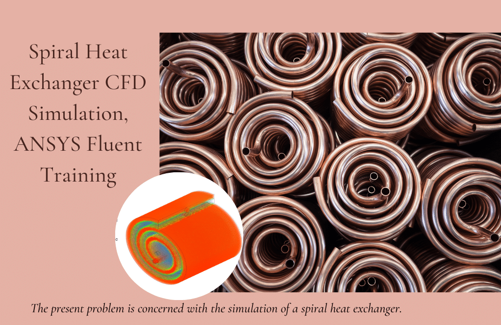
The present problem is concerned with the simulation of a spiral heat exchanger.
Click on Add To Cart and obtain the Geometry file, Mesh file, and a Comprehensive ANSYS Fluent Training Video.To Order Your Project or benefit from a CFD consultation, contact our experts via email ([email protected]), online support tab, or WhatsApp at +44 7443 197273.
There are some Free Products to check our service quality.
If you want the training video in another language instead of English, ask it via [email protected] after you buy the product.
Description
Spiral Heat Exchanger CFD Simulation, ANSYS Fluent CFD Simulation Training
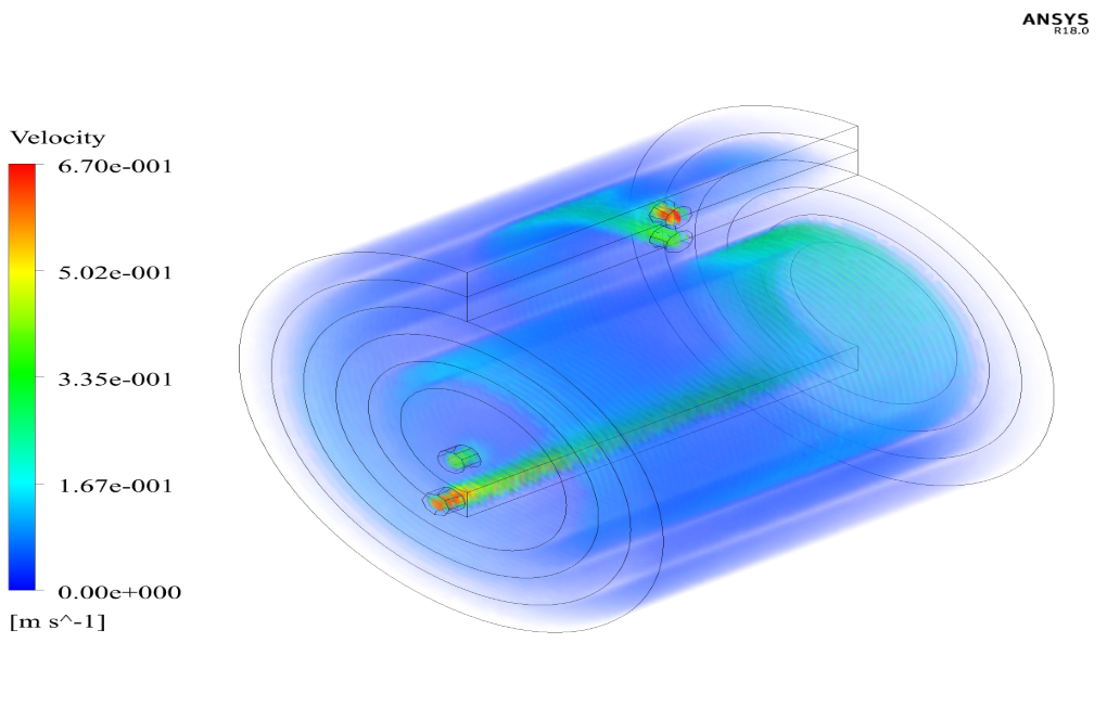
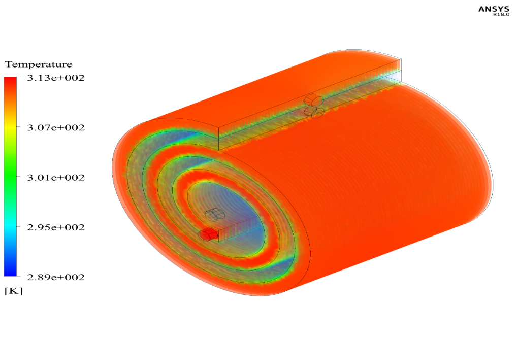
The present problem concerns the simulation of a spiral heat exchanger by ANSYS Fluent software. In this spiral path, two paths for cold water and hot water are used so that the temperature difference between the two water flows causes heat transfer. The hot flow enters the central part of the heat exchanger and exits the heat exchanger environment (laterally) in a perpendicular direction to the inlet area, while the cold current has the opposite direction of the hot stream and enters the heat exchanger environment (laterally) and exits from the central part of the heat exchanger in a direction perpendicular to the input path. The coil plates are embedded between two hot and cold flow paths made of steel with a thickness of 0.01 m. The exterior wall of the model is also made of steel.
Assumption
There are several assumptions used for the present simulation:
The simulation is Steady-State, and the solver is Pressure-Based. Also, the Earth’s gravity effect on the model is considered equal to 9.81 kg.s-1.
Geometry & Mesh (Spiral Heat Exchanger)
The 3-D geometry of the present model (spiral heat exchanger) is designed by the Design Modeler software. The geometry of the present model consists of a cylinder with a separating plate inside the cylinder, which creates two separate spaces for hot and cold fluid flow. Similarly, for each of the two spaces created, an inlet and an outlet cross-section determine the route of the inlet and outlet flow, and their structure is such that the inlet and outlet flow paths are perpendicular to each other. The meshing of the present model is done by ICEM software. The mesh was unstructured and the element number was 450631.
Spiral Heat Exchanger CFD Simulation
Summaries of the problem definition and problem-solving steps are presented in the table:
| Models | |||||
| k-epsilon | Viscous model | ||||
| RNG | k-epsilon model | ||||
| standard wall functions | near-wall treatment | ||||
| on | Energy | ||||
| Boundary conditions (Spiral Heat Exchanger) | |||||
| Mass flow inlet | Inlet type | ||||
| 2 kg.s-1 | mass flow rate | cold water | |||
| 289 K | temperature | ||||
| 3 kg.s-1 | mass flow rate | hot water | |||
| 313 K | temperature | ||||
| Pressure outlet | Outlet type (Spiral Heat Exchanger) | ||||
| 0 Pa | gauge pressure | cold water | |||
| 0 Pa | gauge pressure | hot water | |||
| wall | Walls type | ||||
| insulated | outer walls | ||||
| coupled | middle wall | ||||
| Solution Methods (Spiral Heat Exchanger) | |||||
| Coupled | Pressure-velocity coupling | ||||
| second-order upwind | pressure | Spatial discretization (Spiral Heat Exchanger) | |||
| first-order upwind | momentum | ||||
| first-order upwind | energy | ||||
| first-order upwind | turbulent kinetic energy | ||||
| first-order upwind | turbulent dissipation energy | ||||
| Initialization (Spiral Heat Exchanger) | |||||
| Standard | Initialization method | ||||
| 313 K | temperature | ||||


Misty Schinner –
How do you ensure the accuracy of the mesh in the Spiral Heat Exchanger CFD Simulation?
MR CFD Support –
We use ANSYS Meshing software to generate a high-quality mesh. The software allows us to refine the mesh in areas of interest, ensuring that we accurately capture the heat transfer phenomena.
Annabelle Mayert –
What boundary conditions are used in the Spiral Heat Exchanger CFD Simulation?
MR CFD Support –
We use appropriate boundary conditions based on the specifics of the heat exchanger design and operation. These typically include temperature and flow rate conditions at the inlets and outlets.
Mr. Brody Hammes –
I’m impressed with the level of detail in your product descriptions. It really helps me understand what I’m purchasing.
MR CFD Support –
Thank you! We believe in providing detailed descriptions so our customers can make informed decisions. If you have any more questions, feel free to ask.
Peter Conn –
The training was excellent, and it was easy to follow how to simulate the spiral heat exchanger. I particularly appreciated the detailed set-up, especially the boundary conditions with specific mass flow rates and temperatures for hot and cold water. It made the process clear and practical. Great job!
MR CFD Support –
Thank you for your positive feedback! We’re thrilled to hear that you found our training on the spiral heat exchanger simulation helpful and that the detail provided added clarity to your learning experience. If you have any more questions or need further assistance in your simulations, please don’t hesitate to reach out. Happy simulating!
Gonzalo Monahan –
The spiral heat exchanger simulation uses the RNG k-epsilon model but only lists first-order upwind for momentum and energy. Could using higher-order discretization methods improve accuracy?
MR CFD Support –
Yes, using higher-order discretization methods could potentially improve the accuracy of the simulation. Higher-order methods minimize numerical diffusion and provide better resolution of gradients, which are particularly beneficial in capturing fine-scale flow features within the heat exchanger. However, it is essential to ensure that the mesh is fine and high quality enough to support higher-order methods and that solution stability is maintained throughout the simulation process.
Arianna Walsh –
I’m quite impressed with how the meshing for the spiral heat exchanger was done using ICEM software. The use of an unstructured mesh with that many elements must contribute considerably to solution accuracy, doesn’t it?
MR CFD Support –
Thank you for your positive feedback! Yes, the use of an unstructured mesh with a high element count typically enhances the accuracy of CFD simulations by better capturing the complex geometries and flow characteristics within the spiral heat exchanger. We’re glad to hear that this detail caught your attention and that you appreciate the level of precision in our simulations.
Miss Danielle Renner II –
The quality of your simulations is exceptional. The Spiral Heat Exchanger CFD Simulation is particularly impressive!
MR CFD Support –
Thank you very much! We aim to provide high-quality, detailed simulations. Your feedback is appreciated
Noelia Pfannerstill –
Absolutely thrilled with the level of detail in this Spiral Heat Exchanger CFD Simulation training! Through ANSYS Fluent program teachings, the insights into heat transfer efficiency in a practical design were enlightening. It enhanced my grasp of thermal systems engineering significantly.
MR CFD Support –
Thank you for the kind words! We’re pleased to know that our Spiral Heat Exchanger CFD Simulation training has enriched your understanding of thermal systems. If there’s anything more you wish to explore or need further assistance with, we’re always here to help.
Shanna Weissnat –
I recently completed the CFD Simulation training for the Spiral Heat Exchanger using ANSYS Fluent, and I am genuinely impressed. The structure and design of the program allowed me to understand the complexities behind setting up a practical and effective simulation. With the detailed instructions on setting boundary conditions and using suitable solution methods, I feel more confident in my ability to replicate similar heat exchanger simulations independently.
MR CFD Support –
Thank you for your positive feedback! We’re delighted to hear that our training for the Spiral Heat Exchanger CFD Simulation in ANSYS Fluent has been beneficial to you. It is great to know that our program’s structure and detailed instructions have improved your confidence in performing similar simulations. We aim to provide comprehensive learning tools that empower our customers, and we appreciate you sharing your experience!
Wilmer Connelly –
The tutorial was elaborate and helped me understand the setup on ANSYS Fluent; the explanation of boundary conditions and solution methods was particularly valuable. Great job!
MR CFD Support –
Thank you for your kind words! We are thrilled to hear that our Spiral Heat Exchanger CFD Simulation training provided you with clear and thorough guidance on setting up simulations in ANSYS Fluent. Your satisfaction with our learning resource is greatly appreciated. If you have any more questions or need further assistance, feel free to reach out. Happy simulating!
Elisa Ernser V –
This course seems to be exactly what I was looking for – a practical introduction to Spiral Heat Exchanger simulation. However, does the training also cover post-processing techniques to analyze the performance of the heat exchanger?
MR CFD Support –
Yes, the training includes comprehensive guidance on post-processing techniques, which will help you to examine the temperature distribution, assess the efficiency of thermal exchange within the spiral heat exchanger, and understand other performance metrics through CFD simulation results in ANSYS Fluent.
Mr. Armani Dietrich –
The spiral heat exchanger simulation was clear and easy to follow. The details about the materials, boundary conditions, and mesh generation were well-explained. The use of a coupled solver and upwind discretization methods helped achieve accurate results. It’s impressive how the simulation could effectively represent the temperature profile and flow interactions.
MR CFD Support –
Thank you for your positive feedback! We’re delighted to hear that you found the simulation clear and informative. Our aim is to provide detailed and accurate tutorials that help users understand the process and mechanics behind each simulation. Your satisfaction with the training materials is paramount to us. If you have any further inquiries or need assistance with other simulations, please feel free to reach out.
Prof. Eliza Greenfelder MD –
After completing this training for the Spiral Heat Exchanger CFD Simulation, I feel very confident in my understanding of heat transfer in complex geometries. The detailed setup and results analysis has given me a lot of insight. Kudos to the MR CFD team for creating such comprehensive training material.
MR CFD Support –
We’re delighted to hear that our Spiral Heat Exchanger CFD Simulation training helped you gain a comprehensive understanding. Your confidence in dealing with complex geometries and heat transfer analysis is a testament to the quality of our educational product. Thank you for acknowledging our team’s effort—we truly appreciate it!
Dr. Jakob Boehm –
The description was really detailed and informative! The setup for the simulation is practical, and will help in understanding the heat transfer process in the spiral heat exchanger. Great job on making the learning process clear and engaging.
MR CFD Support –
Thank you for your positive feedback! We’re glad that you found the description detailed and informative. At MR CFD, we strive to provide clear and practical CFD simulation training to help users understand complex processes. Your encouragement motivates us to continue producing high-quality educational materials. If you have any further questions or need assistance, feel free to reach out.
Madisen Hayes –
I recently completed the Spiral Heat Exchanger CFD Simulation training using ANSYS Fluent. The course content was comprehensive and the step-by-step approach was instrumental in understanding the simulation complexities. The assumptions made were clearly outlined, allowing a good grasp of the involved simplifications. I am very impressed with the detailed explanation of the boundary and initial conditions which paved the way for a strikingly realistic simulation. The spiral design was an excellent and practical choice of study, bringing real-world applications into the learning experience.
MR CFD Support –
Thank you for your positive feedback! We are delighted to hear that our Spiral Heat Exchanger CFD Simulation training met your expectations and provided you with a thorough understanding of the processes involved. It’s encouraging to know that the course content was helpful and you found our detailed explanations valuable. Your satisfaction is crucial to us, and we are committed to ensuring a rewarding learning experience for our clients. If you ever have any more insights or need further assistance, please don’t hesitate to reach out.
Paris Schowalter –
I’m really impressed with the level of detail and technical information in the Spiral Heat Exchanger CFD Simulation by ANSYS Fluent. From how to set up the boundary conditions to understanding the meshing process, this will surely help me in my projects. Great work!
MR CFD Support –
Thank you for your kind words! We are delighted to hear that the Spiral Heat Exchanger CFD Simulation training met your expectations and provided valuable insights. Your satisfaction is our top priority, and we look forward to supporting your future projects with MR CFD’s learning products.