Single Reference Frame (SRF) Axial Pump CFD Simulation
Free
- The problem numerically simulates the Axial Pump using ANSYS Fluent software.
- We design the 3-D model by the SpaceClaim software.
- We Mesh the model by ANSYS Meshing software, and the element number equals 36,865.
- The Single Reference Frame is defined to model rotational movement.
To Order Your Project or benefit from a CFD consultation, contact our experts via email ([email protected]), online support tab, or WhatsApp at +44 7443 197273.
There are some Free Products to check our service quality.
If you want the training video in another language instead of English, ask it via [email protected] after you buy the product.
Description
Single Reference Frame (SRF) Axial Pump CFD Simulation, ANSYS Fluent Training
Description
In this project, which has been done with CFD numerical simulation method, an axial pump is simulated. In axial pumps, the fluid flow is in the direction of the impeller shaft axis. Of course, there are different types of axial pumps. The flow direction in them can be between the radial and axial directions.
Axial pumps should be used where high fluid flow and low head are required. In this project, the inlet speed of water is 2 m/s and the outlet is atmospheric pressure. The rotational speed of the pump impeller is 200 rpm, and the Frame Motion module has been used.
The two-dimensional geometry has been produced with SpaceClaim software. The length of the commutating domain is 118 mm, and the width is 117 mm. In addition, The meshing has been done with ANSYS Meshing software, and the type of elements is unstructured. Also, the total number of elements is 36,865.
This CFD project is the 9th episode of the ANSYS Fluent General Training Course.
Methodology: Single Reference Frame (SRF) Axial Pump
The pressure-based solver is employed due to the incompressibility of the water. The gravitational acceleration is ignored. Also, the simulation is performed in steady form. It should be mentioned that the Axisymmetric Swirl option is used. The rotational motion of the flow is modeled by MRF.
Conclusion
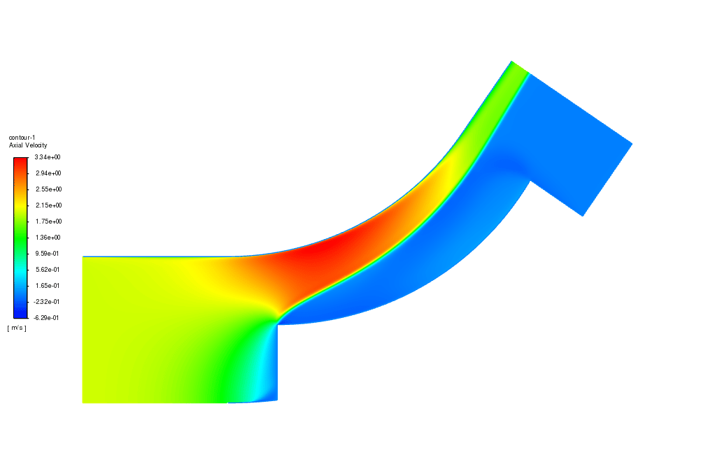
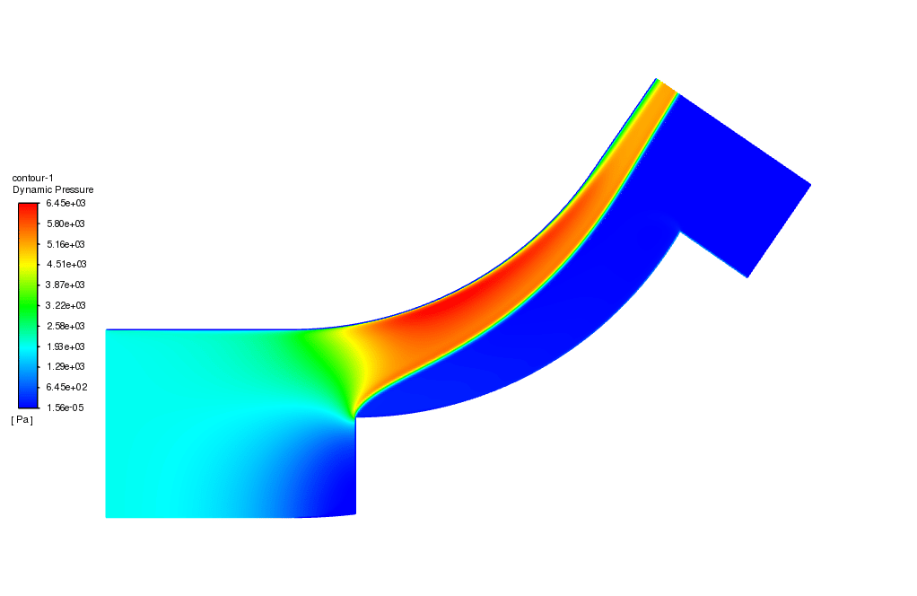
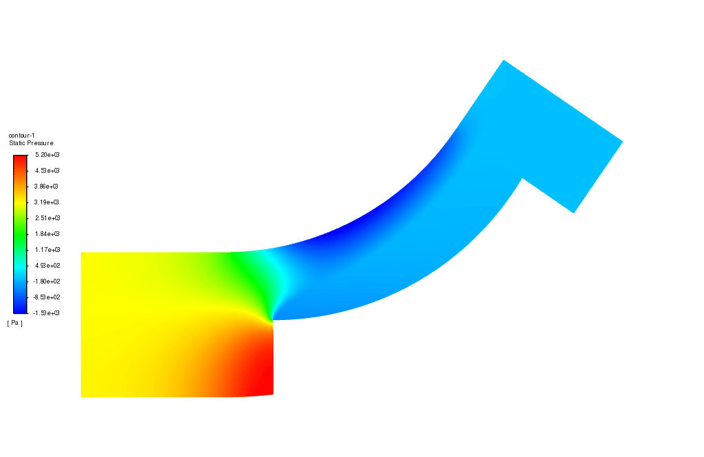
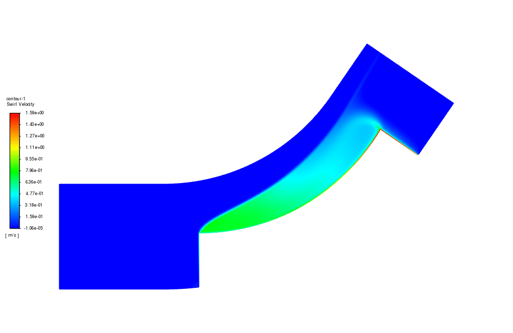
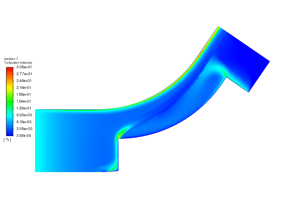
After the simulation, we can see that due to the blade’s rotational speed, the radial component of the velocity at the output increases relative to the input. Also, the dynamic pressure, which is directly related to the velocity of the fluid, increases accordingly.




Mrs. Kiarra Nicolas –
The Single Reference Frame (SRF) method is employed in this simulation, but I’m curious to know if this approach affects the accuracy of the results when compared to a transient simulation using a Sliding Mesh method for the axial pump.
MR CFD Support –
The Single Reference Frame (SRF) method simplifies the computational model by treating the rotating and stationary parts as one reference frame. This method provides a less computationally intensive approach compared to transient simulations with a Sliding Mesh, which models the motion more accurately. While SRF may be somewhat less accurate for capturing transient flow phenomena due to its steady-state assumption, it can still provide a good approximation of the performance of the pump for a constant operation condition.
Miss Vallie Murray –
This product helped me understand axial pumps better. The graphical presentations of dynamic pressure and velocity changes were very clear.
MR CFD Support –
Thank you for your positive feedback! We’re glad to hear that our training was helpful in enhancing your understanding of axial pumps and that the graphical representations contributed to a clearer grasp of the subject.
Kaitlyn Bruen –
This tutorial helped me get underway with axial pump simulations, but I’m intrigued—how does the SRF method ensure accurate representation of the impeller’s motion without actually rotating the mesh?
MR CFD Support –
The SRF method treats the impeller’s rotation in a way that sector of the computational domain where the impeller is located is assumed to be in a rotating frame of reference, while the rest of the domain is stationary. This way, the effect of the rotating blades on the flow is captured without physical mesh rotation, reducing computational complexity while still maintaining accuracy.
Shayna Jast –
This axial pump CFD simulation package looks very comprehensive! Amazing how the rotational motion is modeled and the expected results at the outlet. Great course for understanding pump dynamics.
MR CFD Support –
Thank you for your kind words! We are very pleased to hear that you found the axial pump CFD simulation training comprehensive and helpful for understanding the dynamics of pump operation. Should you have any more questions or need further assistance, feel free to reach out!
Darlene Padberg –
Fantastic tutorial on the Single Reference Frame (SRF) method for axial pump simulations! The detail included along the methodology helped me grasp the concepts cleanly. It particularly piqued my curiosity when learning how a real-life pump’s performance is mapped in the CFD environment.
MR CFD Support –
Thank you for your kind words! We’re thrilled to hear that our ANSYS Fluent training on the SRF Axial Pump gave you clarity on the simulation concepts and was able to enlighten on the real-world performance mapping. Your feedback is incredibly valuable to us. Keep diving into the world of CFD with enthusiasm!
Kennith Raynor II –
Thanks to the detailed training content provided by MR CFD, I could easily understand how the Single Reference Frame (SRF) is utilized in axial pump simulations. The gradual increase in dynamic pressure and the effect of the impeller’s rotation on the fluid flow are well-demonstrated in the results. The methodology covered in this episode provides an excellent guide for further studies in axial pump dynamics.
MR CFD Support –
Thank you for your positive feedback! We’re delighted to hear that our training material helped enhance your understanding of axial pump simulations and the utilization of SRF. Your insights into dynamic pressure changes and fluid flow effects due to the impeller´s rotation are exactly what we hope to provide through our CFD project training series. We appreciate your thoughtful review and look forward to any questions or discussions you might have about our future products.
Ines Champlin –
This training walks users through every step of axial pump simulation. It’s one of the best I’ve gone through!
MR CFD Support –
Thank you so much for your kind words! We’re glad you found the axial pump simulation training useful and comprehensive. If you have any more feedback or require further assistance, please don’t hesitate to reach out.
Eugene Gusikowski –
The axial pump simulation really helped me visualize the behavior within the pump. The explanation of the methodology was clear, too. Could you please clarify how the dynamic pressure was visualized in the simulation’s results?
MR CFD Support –
We’re glad to hear the simulation was helpful to you! Dynamic pressure in the simulation was visualized using the pressure-based solver in ANSYS Fluent. Contours of dynamic pressure were generated, showing how it increases with the fluid’s velocity due to the impeller’s rotation. The results illustrate the higher dynamic pressures at the pump’s discharge compared to the inlet, indicating the pump’s functionality in increasing fluid pressure. If you’d like to view specific contour plots or numeric data, those can often be extracted and reviewed within the post-processing results section in ANSYS Fluent.
Melisa Sipes –
I really appreciate the concise and clear explanations provided on the Single Reference Frame (SRF) Axial Pump CFD Simulation. You’ve made the technical details accessible even for those with limited CFD knowledge.
MR CFD Support –
Thank you for your kind words! We’re delighted that you found the explanations on the SRF Axial Pump CFD Simulation clear and understandable. It’s our goal to make complex concepts accessible and informative. If you have any further questions or need more insights, feel free to ask. Your interest is our motivation!
Novella Yost –
What is the benefit of using the MRF method in this type of CFD simulation?
MR CFD Support –
The MRF (Multiple Reference Frame) method enables us to simulate the rotating behavior of the pump impeller without actually simulating the motion of the object, thus simplifying the mesh requirements and reducing computational time. It allows us to obtain approximation on how the impeller’s rotation influences the fluid dynamics within the system.
Lura Price II –
I really appreciate the in-depth explanation and methodology provided for this SRF Axial Pump CFD simulation. It was a great learning experience following this detailed ANSYS Fluent project.
MR CFD Support –
We’re thrilled you found the training session useful and yielded a great learning experience for you. At MR CFD, we always strive to provide deep insights and comprehensive explanations for all our projects. Thank you for choosing us for your learning journey in CFD simulation!
Dr. Anibal Jaskolski Jr. –
I’m truly impressed by the detail in the SRF axial pump training. The step-by-step methodology and clear results were invaluable. It made conceptualizing the pump’s mechanics a breeze. Keep up the extraordinary work!
MR CFD Support –
Thank you for your kind words! We’re thrilled to know the details and methodology were helpful in understanding the axial pump simulation. If you have any more feedback or need assistance with future simulations, feel free to reach out!
Anastacio Gerlach –
I’m intrigued by how MRF successfully models the rotational motion. Can you explain why MRF is more suitable for this simulation than other methods?
MR CFD Support –
MRF, or the Multiple Reference Frame method, is suitable for simulating steady-state conditions where we have a rotating part in a fluid flow. It assumes that while the impeller rotates, the flow reaches a quasi-steady state where at each time slice it looks the same. This is valuable in applications like these saw pumps where one portion of the pump is in motion relative to the stationary parts. The advantage over moving mesh simulations (Sliding Mesh) is that it’s simpler and less computationally expensive, making it better for initial design iterations where you look for general flow characteristics rather than capturing transient behaviors.
Keshawn Legros –
The step-by-step guide made following the procedure for the SRF Axial Pump simulation exceptionally clear. Great work on explaining the setup!
MR CFD Support –
Thank you for your positive feedback! We’re thrilled to hear that the guide was clear and helpful. We strive to provide detailed and easy-to-follow instructions for our simulations. If you have any more questions or need further assistance, please don’t hesitate to ask.
Shanie Langworth –
I had great success using the SRF Axial Pump simulation-CFD course from MR CFD Company; it helped me a lot with my project on axial pump optimization. The accompanying course materials and descriptive approach eased my learning curve significantly. Big thumbs up!
MR CFD Support –
We’re delighted to hear about your successful experience with our SRF Axial Pump simulation course and that it aided in your project. Our team strives to provide comprehensive learning materials to facilitate an effective understanding of CFD applications. Thank you for the positive feedback!
Dr. Gaston Beahan –
The training was quite thorough. The visuals and the step-by-step method really helped solidify the understanding of the SRF process.
MR CFD Support –
Thank you for your positive feedback! We’re thrilled to hear that our ANSYS Fluent training was helpful and that the visuals and methodology were effective in enhancing your understanding. If you have any further questions or need additional resources, feel free to reach out.
Ms. Felicity Beier –
The explanation on how the MRF model is incorporated is a bit unclear. Can you provide more details on how the MRF approach is applied for simulating the rotational effects within the pump in ANSYS Fluent software?
MR CFD Support –
Absolutely! The MRF method allows us to account for the rotational movement of the impeller without simulating the actual mechanical rotation, saving computational resources. In ANSYS Fluent, one can define a rotating zone that encases the impeller. This zone, called a rotating reference frame, moves at a specified angular velocity reflecting the impeller’s speed, enabling us to predict the impact of the rotation on the fluid flow accurately.
Gabriel Lowe –
I was absolutely thrilled with the ‘Single Reference Frame (SRF) Axial Pump CFD Simulation’ course. The clear step-by-step methodology made it so much easier to understand the complexities of axial pump simulation. The final comparison of velocity components and dynamic pressure differentiation was particularly illuminating!
MR CFD Support –
Thank you for your positive feedback! We’re so glad to hear that our course on SRF Axial Pump CFD Simulation was helpful and that you enjoyed the detailed explanations and outcomes assessment. Your understanding and appreciation motivate us to continue delivering high-quality training courses.