Single Sided Ventilation in Room Considering a Heater, ANSYS Fluent Training
$80.00 Student Discount
The problem simulates the airflow of air inside a room considering a heater and checking the heat transfer inside the room by single-sided ventilation.
Click on Add To Cart and obtain the Geometry file, Mesh file, and a Comprehensive ANSYS Fluent Training Video.To Order Your Project or benefit from a CFD consultation, contact our experts via email ([email protected]), online support tab, or WhatsApp at +44 7443 197273.
There are some Free Products to check our service quality.
If you want the training video in another language instead of English, ask it via [email protected] after you buy the product.
Description
Project Description
The problem simulates the airflow inside a room considering a heater and analyses the heat transfer inside the room using single-sided ventilation by ANSYS Fluent software. Inside the room, an aluminum radiator is used as a heat source with an output energy of 23469 W.m-3. Also, a window is placed on one of the lateral walls for the outlet airflow. The boundary condition of the pressure outlet with the pressure equal to the ambient pressure (atmospheric pressure) and the backflow air temperature equal to the room temperature is used. The purpose of this study is to investigate the airflow behavior in the room.
Geometry & Mesh
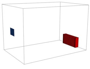
The 3-D geometry of the present model is designed using Design Modeler software. The model consists of a room measuring 2.15 m ⨯ 2.16 m ⨯ 3.32 m, with a rectangular cube heater at the bottom of one of its sidewalls. The following figure shows the geometry.
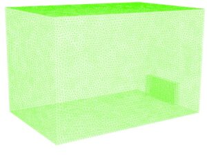
The meshing of the present model has been done by ANSYS Meshing software. The mesh type is unstructured and the element number is 987087. The following figure shows a view of the mesh.
Single-Sided Ventilation CFD Simulation
To simulate the present model, several assumptions are considered, which are:
- The Pressure-Based solver has been performed.
- Simulation has been performed in both fluid and heat transfer modes.
- The present model is steady-state.
- The effect of gravity is 9.81 m.s-2 on the fluid.
Here is the summary of the steps for defining a problem and its solution in the table:
| Models | ||
| Viscous model | k-epsilon | |
| k-epsilon model | realizable | |
| near-wall treatment | standard wall function | |
| Boundary conditions | ||
| Outlet | Pressure outlet | |
| gauge pressure | 0 Pascal | |
| Walls | Wall | |
| Wall motion | stationary wall | |
| heat flux | 0 W.m-2 | |
| Solution Methods (single-sided ventilation) | ||
| Pressure-velocity coupling | SIMPLE | |
| Spatial discretization | pressure | second-order |
| momentum | second-order upwind | |
| density | second-order upwind | |
| turbulent kinetic energy | second-order upwind | |
| turbulent dissipation rate | first-order upwind | |
| energy | second-order upwind | |
| Initialization | (single-sided ventilation) | |
| Initialization method | Standard | |
| gauge pressure | 101325 pascal | |
| velocity (x,y,z) | 0 m.s-1 | |
| temperature | 300 K | |
Single-Sided Result
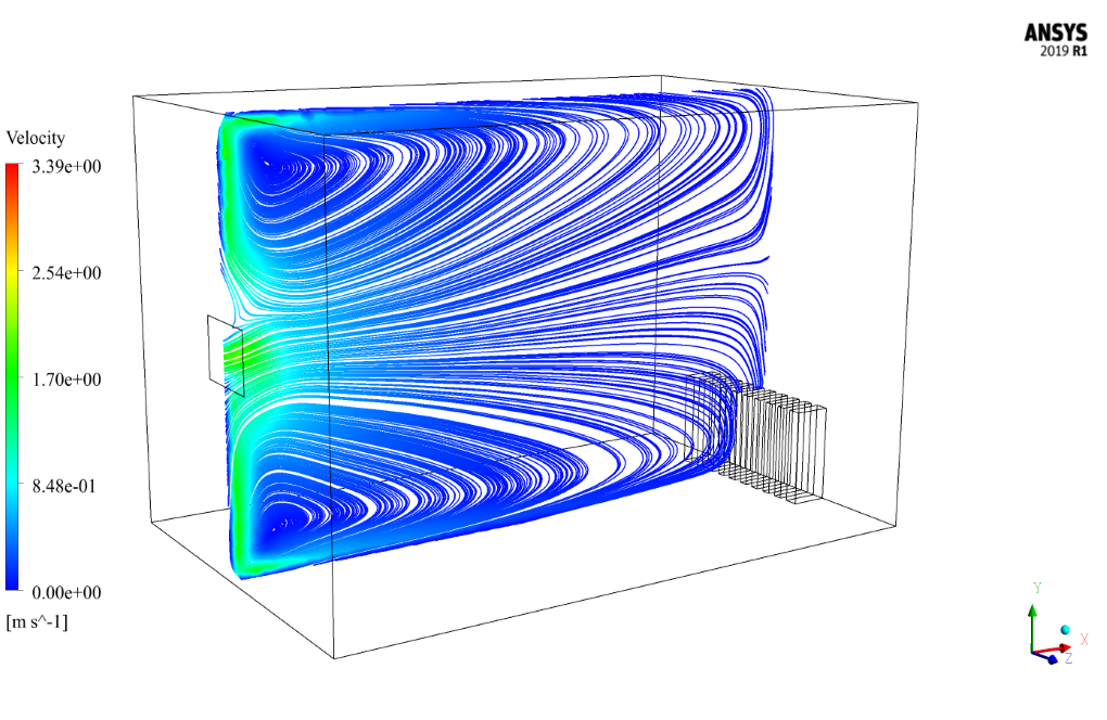
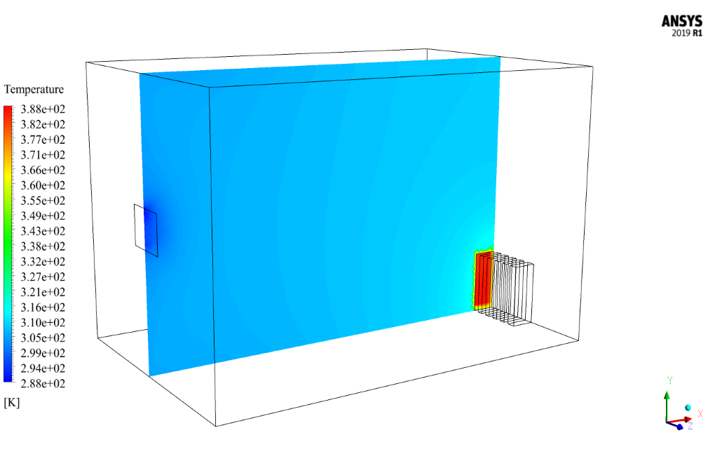
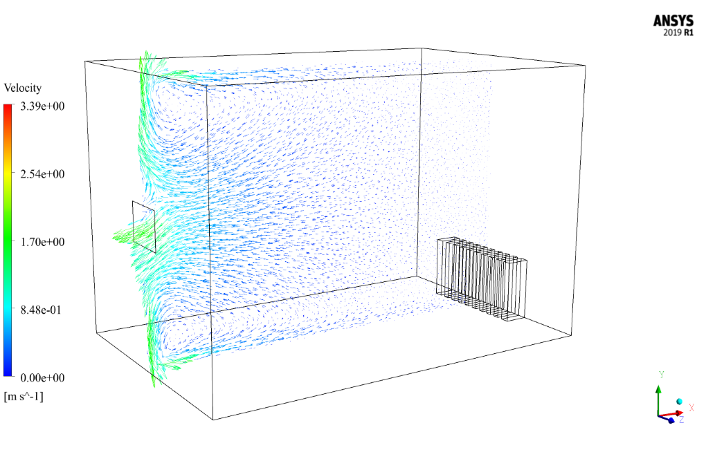
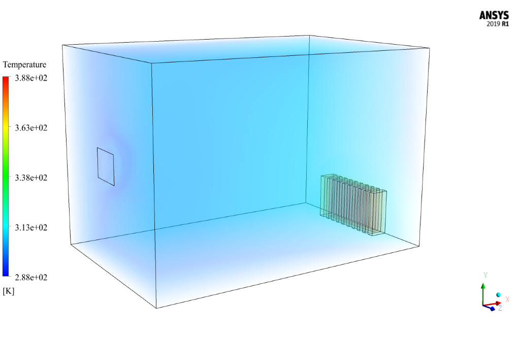
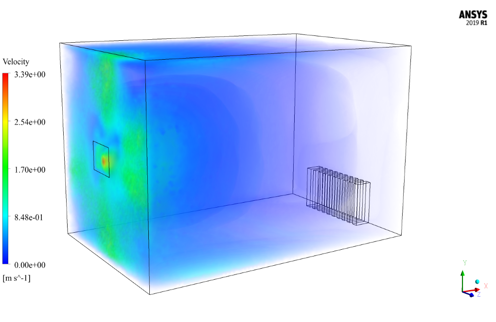
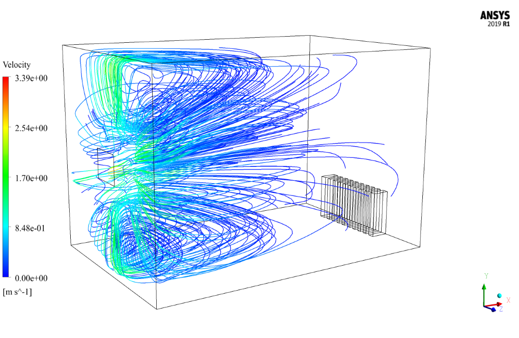
At the end of the solution process, two-dimensional and three-dimensional contours of pressure, temperature, and velocity, as well as two-dimensional and three-dimensional velocity vectors, are obtained. The two-dimensional contours and vectors are drawn in two sections, XY and YZ so that the contours on the YZ page are drawn in three different sections.

Annabell Balistreri –
Can this simulation be used to optimize the placement of the heater and the ventilation?
MR CFD Support –
Absolutely! The results from this simulation can provide valuable insights into the optimal placement of the heater and the ventilation to achieve the desired temperature distribution.
Gaylord Smitham –
This product seems comprehensive, but I’m curious about how natural convection has been taken into account alongside the ventilation in this setup.
MR CFD Support –
In this simulation, natural convection is taken into account by including the effect of buoyancy due to temperature differences. The density of the air changes with temperature, causing airflow due to the gravity vector being activated in the simulation. Together with the forced convection from the single-sided ventilation, this gives a realistic portrayal of airflow inside the room.
Greyson Ryan –
The heater inside the room has an output energy of 23469 W.m-3. Was this the optimal heating power for maintaining a comfortable room temperature during the simulation, or were various heating powers analyzed to determine this value?
MR CFD Support –
In the simulation, we have used the specified heating power of 23469 W.m-3 as the input for the heater. This value was pre-determined as part of the simulation setup and was not specifically optimized within this simulation study. If needed, additional simulations can be performed with different heating powers to analyze the impact on room temperature and optimize for thermal comfort.
Sam Zboncak –
Thank you for the comprehensive training on Single Sided Ventilation using ANSYS Fluent. The step by step guide was highly useful in understanding how to set up the simulation. I appreciated the clear explanation of gravitational effects on fluid flow and the detailed breakdown of the boundary conditions applied. The way the coursework integrated heat transfer with fluid flow analysis enhanced my grasp of real-world HVAC systems. Excellent training material!
MR CFD Support –
Thank you so much for your positive feedback! We’re thrilled to hear our Single Sided Ventilation training with ANSYS Fluent was helpful in enhancing your understanding of HVAC systems and simulation setup. Your comprehension of the connection between heat transfer and fluid flow analysis is crucial and we’re glad our material could assist in this. If you need further assistance or more resources for learning, feel free to reach out to us!
Kurt O’Reilly –
Is this study suitable for simulating temperature distribution in large halls, or is it restricted to small rooms only?
MR CFD Support –
The methods and processes used in this study, including single-sided ventilation, heat source modeling, and airflow analysis, are scalable and can be adapted to simulate temperature distribution in larger spaces such as halls with adjustments to the model’s dimensions and boundary conditions to fit a larger scale. The fundamental principles remain consistent across different sizes of rooms or halls.
Prof. Darrion Romaguera DVM –
I really enjoy how detailed the project is. The inclusion of gravity impact on the fluid adds a layer of realism. Cheers to the team for crafting such a comprehensive simulation training.
MR CFD Support –
Thank you for your positive feedback! We’re delighted to hear that you appreciate the details and realism of our simulation. Our team always aims to provide comprehensive and accurate training materials, and it’s rewarding to know when our efforts resonate with our customers.
Serena West –
I just wanted to express how happy I am with the Single Sided Ventilation in Room CFD training using ANSYS Fluent. The detail on the simulation steps and thorough explanation of the geometry and boundary conditions made it really easy to follow. Plus, the explanations of solver settings were superb. Great job on creating such an informative course!
MR CFD Support –
Thank you so much for your kind words! We’re thrilled to hear that you found the training so informative and easy to follow. Our team puts a lot of effort into making sure our courses are detailed and educational. We’re glad to know it’s appreciated, and we hope you’re able to apply the skills learned effectively in your simulations. If you need any further assistance or have more feedback, don’t hesitate to reach out!
Wilhelmine Bailey –
How does the simulation model the heat transfer in the room?
MR CFD Support –
The simulation uses the energy equation to model the heat transfer from the heater and the walls of the room.
Dexter Kling –
Very detailed tutorial with excellent visualizations! It’s incredible how the heating effect and airflow patterns are captured within the room simulation.
MR CFD Support –
Thank you for your kind words. We’re delighted to hear that the visualizations and the level of detail in the ‘Single Sided Ventilation in Room Considering a Heater, ANSYS Fluent Training’ helped you understand the effects of heat and airflow in an indoor setting!
Marcellus Cronin –
What a fantastic learning experience! The ‘Single Sided Ventilation in Room Considering a Heater, ANSYS Fluent Training’ was incredibly insightful. The attention to detail in the simulation setup, especially the careful consideration of boundary conditions and meshing, laid a strong foundation for understanding heat transfer and airflow behavior in an indoor environment. Truly appreciated the step-by-step guidance provided for setting up the simulation, ensuring clarity throughout the learning process. Amazing job on demonstrating both 2D and 3D results; they effectively illustrated the temperature and velocity distribution across the room, providing a comprehensive view of the ventilation efficiency.
MR CFD Support –
Thank you so much for your positive feedback! We’re thrilled to hear that you had an excellent experience with the ‘Single Sided Ventilation in Room Considering a Heater, ANSYS Fluent Training.’ It warms our hearts to know that we were able to provide valuable insights into the complexities of CFD simulations and the software’s capabilities. Your satisfaction is our highest priority, and your compliment indicates that we’re on the right track. If you ever need further assistance or would like to explore more topics, we’re here for you. Keep learning and keep simulating!
Allison Kirlin Sr. –
Just wanted to drop a note of thanks for the incredibly detailed
MR CFD Support –
We’re thrilled to hear that you found our ‘Single Sided Ventilation in Room Considering a Heater, ANSYS Fluent Training’ product to be detailed and informative. Our goal is to provide thorough and high-quality resources that can deepen understanding and facilitate learning. Thank you for choosing our product, and we appreciate you taking the time to share your positive experience!
Kailyn Johns –
The heater output is pretty specific. Did using an aluminum radiator as the heat source affect the accuracy of the simulation? I am intrigued by the material choice.
MR CFD Support –
Thank you for the interesting question! Yes, the choice of the aluminum radiator as a heat source does affect the accuracy of the simulation. Aluminum, being a good conductor of heat, would ensure a more uniform heating profile compared to other possible materials. It probably was considered for its high thermal conductivity which would impact the simulation results by allowing for a more consistent distribution of heat within the room, leading to a more realistic simulation of thermal patterns and airflow behavior.
Prof. Israel Lockman I –
I’m delighted with how the product shows efficient heat transfer analysis in a realistic setting. The aluminum radiator heat output and the meticulous setup of single-sided ventilation reflect the quality and assets of ANSYS Fluent simulation capabilities.
MR CFD Support –
Thank you for such a positive review! We’re glad you appreciate the thoroughness of the setup for the single-sided ventilation study and the detail provided in explaining the role of the heater. If you’re looking to delve deeper or take on new simulation projects, remember that MR CFD is here to support you with expertise in ANSYS Fluent.
Israel Simonis –
This training has been a fantastic resource. The detail on the boundary conditions and solution methods provided immediate improvement in my understanding of single-sided ventilation systems. I’m particularly impressed with the depth of analysis for airflow behavior in presence of a heater. My compliments to MR CFD for an excellent module.
MR CFD Support –
Thank you for your positive feedback! We are thrilled to hear that our ANSYS Fluent training on single-sided ventilation with a heater helped enhance your understanding and provided valuable insights. MR CFD strives to deliver comprehensive and detailed materials to aid in learning complex simulations. Your appreciation means a lot to us!
Maya Lesch DVM –
The well-organized materials and the depth of the analysis exceeded my expectations! Yet, I just wondered about one aspect—how does including the heater and accounting for that energy source 23469 W.m-3 affect the overall temperature distribution in the room?
MR CFD Support –
Thank you for your kind words. The heater plays a significant role in the simulation. Including the heater with a given energy source of 23469 W.m-3 introduces a thermal plume into the room, which results in a non-uniform temperature distribution. Convection currents cause the air to rise above the heater and subsequently circulate throughout the room, altering the temperature distribution. The simulation results correctly capture the impact of the radiator on the air temperature, showcasing areas of higher temperature near the heater and cooler regions farther away.
Carson McGlynn –
How are the results of the simulation visualized?
MR CFD Support –
The results are visualized using contour plots of temperature and velocity, as well as pathlines to show the flow pattern of the air.
Alexis Waters Jr. –
The aluminum radiator in this simulation acts as a heat source. Can you describe how it affects the temperature distribution in the room?
MR CFD Support –
The aluminum radiator generates heat energy with an output of 23469 W.m-3 and acts as the main heat source in the room. As a result, it creates a thermal plume of rising hot air due to its higher temperature compared to the cold air within the room. This induces a convective flow that drives the air upwards and towards the outlet window, hence disturbing the temperature distribution throughout the space. The effect of the radiator introduces a temperature gradient, warmer near the heater and cooler away from it.
Adriel Kshlerin –
I greatly enjoyed the thorough analysis of single-sided ventilation with a heater. Especially insightful was seeing the impact of the heater on the air circulation within the simulation – it really helped me understand the practical applications of convection in room heating. Also, the detailed mesh work is impressive. Great job on providing comprehensive training material!
MR CFD Support –
Thank you for your kind words and positive feedback! We’re delighted to hear that our simulation and training material provided you with a clear understanding of convection and its role in room heating dynamics. If you have any more questions or need further assistance, we’re here to help!
Gabe Quigley –
I was impressed with the clarity of the simulation process for the single-sided ventilation with a heater. The explanations were comprehensive, and the results seem thorough. It’s always a challenge to accurately simulate heat distribution and airflow, but it looks like this training covered all aspects well. Great job on demonstrating the realistic application in ANSYS Fluent.
MR CFD Support –
Thank you for your positive feedback! We aim to provide detailed and comprehensive learning materials to ensure our users can effectively understand and apply CFD simulations in various scenarios. It’s wonderful to hear that you found the training for the single-sided ventilation with a heater to be clear and thorough. Your comments are very encouraging to our team as we continue to develop and improve our learning products. If you have any further insights or need additional assistance, feel free to reach out!
Ruby Bartoletti –
I appreciated learning how single-sided ventilation affects room temperature through this detailed simulation. The explanation of the mesh and boundary conditions provided a comprehensive understanding of the process. Great material for anyone interested in environmental engineering and HVAC!
MR CFD Support –
Thank you for your kind words! We’re delighted to hear that you found the materials informative and helpful for understanding the concept of single-sided ventilation in environmental engineering and HVAC. We strive to provide detailed and thorough explanations in our simulations, and it’s rewarding to know it’s appreciated. If you have any further questions or need additional information, feel free to reach out!
Hal Torp –
This seems like a comprehensive simulation for studying the air flow and heat transfer in a room with a heater. In the results section, are you trying to visualize how the heat from the heater impacts the overall temperature distribution in the room?
MR CFD Support –
Yes, precisely. The results, like temperature contour plots, help visualize and understand how heat from the aluminum radiator (heater) affects the air temperature distribution within the room, ensuring that the heating system is efficient and revealing the effectiveness of single-sided ventilation in maintaining thermal comfort. Additionally, velocity contours and vectors offer insights into the airflow patterns due to natural convection and ventilation flows.
Laury Crona II –
It was impressive to see how the simulation handled the heat from the heater and the room’s airflow! Great job demonstrating the thermal effects and ventilation.
MR CFD Support –
Thank you for your kind words! We strive to deliver comprehensive simulations that effectively demonstrate complex thermal interactions and airflow patterns. It’s great to hear that we’ve managed to showcase these effects to your satisfaction. If you need further information or assistance, please let us know!
Cody Jakubowski –
I just finished the Single Sided Ventilation in Room Considering a Heater training using ANSYS Fluent and I am impressed. The detailed steps for problem definition and the solution approach were meticulously outlined, making it quite easy to follow through with the simulation. Understanding how the heat source affects air flow and temperature distribution in the room was fascinating.
MR CFD Support –
Thank you for your positive feedback! We are thrilled that our step-by-step approach in the Single Sided Ventilation training helped you to easily navigate through ANSYS Fluent and that the simulation enhanced your understanding of heat transfer and airflow dynamics. Your success with the training is very important to us, and we are glad to hear that the material met your expectations.
Joseph Robel II –
What is the material of the walls in the simulation room?
MR CFD Support –
The material of the walls in the simulation is not explicitly mentioned in the provided description, however, the boundary conditions state that the walls are considered stationary with a heat flux of 0 W.m-2, indicating that for the purpose of this simulation, the wall material impact is not a primary focus or is assumed to be insulating with respect to thermal calculations.
Verlie Stanton –
The various results obtained from the simulation offer critical insight into the performance of single-sided ventilation with a heat source in a room. By understanding the distribution and behavior of airflow and temperature, it is possible to propose improvements to the overall design and functionality of ventilation systems. The combination of full geometry modeling, the considered assumptions, and thorough boundary settings provide a comprehensive overview of the indoor climate, emphasizing the vital role of CFD in environmental control within buildings.
MR CFD Support –
Thank you for your valuable feedback! We are delighted to know that the training on single-sided ventilation in a room with a heater meets your expectations and provides you with the insight necessary for understanding and enhancing ventilation systems. CFD indeed plays a crucial role in the advancement of indoor environmental control, and we’re glad our product could contribute to that understanding.
Dr. Arden Blanda DVM –
Very impressed with the level of detail in this simulation of single-sided ventilation considering a heater. The thoroughness of the boundary conditions results in a realistic modeling of airflow and temperature distribution in the room. Enjoyed learning from it!
MR CFD Support –
Thank you for taking the time to review our ANSYS Fluent Training! We’re delighted to hear that you found the simulation details and narrative educational and helpful. Your positive feedback is greatly appreciated!