
Slat and Flap Devices Effects on an Aircraft Wing
$100.00 Internship
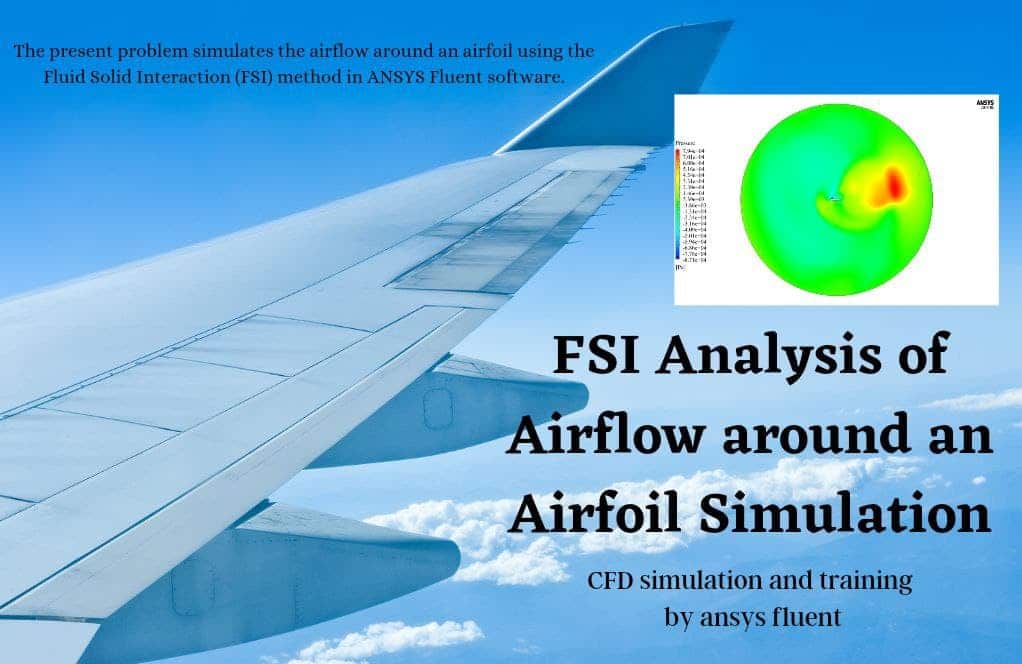
The present problem simulates the airflow around the aircraft wing with a flap and slat, using ANSYS Fluent software.
Click on Add To Cart and obtain the Geometry file, Mesh file, and a Comprehensive ANSYS Fluent Training Video.To Order Your Project or benefit from a CFD consultation, contact our experts via email (info@mr-cfd.com), online support tab, or WhatsApp at +44 7443 197273.
There are some Free Products to check our service quality.
If you want the training video in another language instead of English, ask it via info@mr-cfd.com after you buy the product.
Description
Slat and Flap Devices Effects on an Aircraft Wing, ANSYS Fluent Training
The present problem simulates the airflow around the aircraft wing with a flap and slat, using ANSYS Fluent software. In this project, a 3D airplane wing is designed; In such a way, a Flap is on the trailing edge, and a Slat is on the leading edge of the wing.
A flap is a small aerodynamic surface placed on the trailing edge of an aircraft wing to increase the lift force on the aircraft wing. Lift force is the main factor holding the aircraft in the air and overcoming the force of the aircraft’s weight. Lift force is directly related to the aircraft’s speed; As the aircraft speed increases, the lift force is amplified, and as the aircraft speed decreases, the lift force decreases. Therefore, when the aircraft’s speed is reduced, such as when the aircraft takes off or lands, the lift force decreases, and, as a result, the lift force must be strengthened. Therefore, the flap is used on the fuselage of the aircraft wing to compensate for this decrease in lift force by rotating around its axis at the trailing edge and increasing the contact surface of the wing with the airflow.
A slat is a small aerodynamic surface that sits on the leading edge of an aircraft wing. Similarly, the air is used at the wing leading edge to increase the lift force when the aircraft speed slows down, such as when the aircraft takes off or lands. The Slat rotates around its axis at the wing leading edge and increases the wing contact surface with the air stream. Also, the slat can increase the area of the aircraft wing, increase the drag force and help the aircraft land more slowly during landing.
The airflow in the vicinity of the aircraft wing is compressible. This simulation is based on a density-based solver. Also, due to the compressibility of the airflow, the ideal gas model has been used to define the amount of airflow density changes.
In terms of boundary conditions, airflow velocity in the computational area around the wing is 271.958 m.s-1 along the x-axis and 40.79 m.s-1 along the y-axis. Also, the airflow temperature is equal to 305.5 K.

Geometry & Mesh
The present model is designed in three dimensions using Design Modeler software. The model is a wing of an aircraft with an Slat on the leading edge and a Flap on the trailing edge.


We carry out the model’s meshing using ANSYS Meshing software, and the mesh type is unstructured. The element number is 5658021. The following figure shows the mesh.

CFD Simulation
We consider several assumptions to simulate the present model:
- We perform a density-based solver.
- The simulation is steady.
- The gravity effect on the fluid is ignored.
The following table represents a summary of the defining steps of the problem and its solution:
| Models | ||
| Viscous | k-epsilon | |
| k-epsilon model | Spalart-Allmaras | |
| Boundary conditions | ||
| Inlet | Velocity Inlet | |
| x-velocity | 271.958 m.s-1 | |
| y-velocity | 40.79 m.s-1 | |
| temperature | 305.5 K | |
| Outlet | Pressure Outlet | |
| gauge pressure | 0 pascal | |
| Walls (wing, flap, slat) | Wall | |
| wall motion | moving wall | |
| heat flux | 0 W.m-2 | |
| Symmetry | Symmetry | |
| Methods | ||
| Formulation | implicit | |
| flow | second-order upwind | |
| modified turbulent viscosity | second-order upwind | |
| Initialization | ||
| Initialization methods | Standard | |
| gauge pressure | 0 pascal | |
| x-velocity | 271.958 m.s-1 | |
| y-velocity | 40.79 m.s-1 | |
| z-velocity | 0 m.s-1 | |
| temperature | 305.5 K | |
Results & Discussions
At the end of the solution process, two-dimensional counters of pressure, temperature, velocity, Mach number, and density are obtained perpendicular to the plane of the airflow area adjacent to the fuselage. Two-dimensional path lines and two-dimensional velocity vectors are also obtained on the same plane. Also, a pressure contour is obtained on the surface of the fuselage. The contours clearly show changes in velocity, density, and airflow pressure around the fuselage. This indicates the occurrence of a pressure difference and the creation of a lift force. Also, the comparison of the contour of pressure on the aircraft’s fuselage from the two upper and lower views of the aircraft shows the production of lift force against the force of weight.
Reviews
You must be logged in to post a review.

Ben Cremin –
The provided details on ANSYS Fluent simulation of slat and flap effects are extensive! The incorporation of a steady, density-based solver, and dual velocity components to model airflow are appreciated measures for accuracy. I’d love to learn more – could you share if any specific results on lift variations with and without the deployment of slat and flap devices were observed in this study?
MR CFD Support –
Thank you for your kind words about the training content on the slat and flap devices effect simulation. In response to your question – yes, the simulation results indeed demonstrate variations in lift with the deployment of slat and flap devices. When the devices are deployed, the pressure contours on the surface of the wing distinctly indicate increased lift force. This effect is observable through increased velocity and reduced pressure on the wing’s upper surface, aligning with aerodynamic principles. However, to get precise figures and quantitative data on the lift enhancement, kindly refer to the source content or further documentation provided with the training product.
Leopold Beer –
I appreciate the depth of analysis in his training module! The detailed examination of airflow changes over an aircraft wing with deployed slat and flap devices provided me with a much clearer understanding of the lift forces in various stages of flight, especially during critical maneuvers like takeoff and landing. The clarity in explaining the setup for boundary conditions and the solver was excellent. The usage of high-fidelity CFD tools like ANSYS Fluent, coupled with a high-resolution mesh, rightfully showcased how modern simulation technology can drive aerospace design forward. I’m now much more confident about applying these principles in my own aerospace engineering projects.
MR CFD Support –
Thank you for taking the time to leave such a thoughtful review! We’re delighted to hear that you found the ‘Slat and Flap Devices Effects on an Aircraft Wing’ training module informative and beneficial for your understanding of aerodynamic forces on aircraft wings. Knowing that it has helped improve your confidence in applying simulation principles to your aerospace projects is incredibly rewarding for our team. We’re committed to providing high-quality, detailed analysis tools to assist our customers in their engineering challenges. Don’t hesitate to reach out if you need further assistance or more resources for your projects!
Prof. Rickey Harber –
Great details on the simulation! Could you share any insights on how flap and slat deflection angles are determined for different phases of flight such as takeoff and landing in the simulation?
MR CFD Support –
Glad you found the details informative! In the simulation, flap and slat deflection angles would typically be chosen based on empirical data and aerodynamic principles suitable for the specific phases of flight such as takeoff and landing. These angles are crucial for maximizing lift during low-speed operations. For instance, higher deflection angles are used during takeoff to generate the necessary lift at lower speeds. Similarly, during landing, flap and slat settings are chosen to ensure a slower descent and touchdown speed, while maintaining enough lift to keep the aircraft aloft. The determination of these angles would depend on the aircraft design, the desired performance characteristics, and safety factors.
Maude Hermiston –
This tutorial seems quite comprehensive. Does it include any guidelines on interpreting the aerodynamic performance changes when flaps and slats are deployed compared to when they are retracted?
MR CFD Support –
Yes, the tutorial provides guidelines on how the deployment of flaps and slats affects aerodynamic performance. It explains that by deploying these devices, the contact surface area of the wing with the air increases, enhancing lift at lower speeds during takeoff and landing, and also facilitates increased drag to support safer landings at lower speeds. The results section will likely show a detailed analysis of such effects through various CFD results like pressure and velocity contours on and around the wing.
Kaya Pacocha PhD –
This product review is excellent! The detailed explanation of the effects slat and flap devices have on an aircraft wing using ANSYS Fluent is impressive. The complexity of simulation accounted for air speed, lift force, and how these aerodynamic surfaces affect the aircraft’s performance. The thorough description of how the problem is setup, simulations run, and results analyzed makes me feel like I have gained significant insight into computational fluid dynamics. It seems like your team has gone above and beyond to ensure accurate results and help users understand the aerodynamic behavior during critical phases such as takeoff and landing.
MR CFD Support –
Thank you for your positive review of our ANSYS Fluent Training on the effects of slat and flap devices on an aircraft wing. We are pleased to see that the detailed information provided was helpful and insightful for you. Our team strives to present complex simulations in an understandable way to support your learning and application of computational fluid dynamics. Your satisfaction with our product makes our efforts worthwhile. We appreciate your kind words and look forward to serving you with more high-quality training materials in the future.
Stella Gusikowski –
This CFD training material was very helpful. The explanations on how the slat and flap increase lift and the choice of boundary conditions tied the theoretical aspects to practical applications nicely. Highly appreciated!
MR CFD Support –
We’re thrilled to hear that our training material on the slat and flap effects assisted you in understanding the practical applications of these aerodynamic enhancements. Thank you for taking the time to share your positive experience. Your feedback is very much appreciated!