SOFC (Solid Oxide Fuel Cell) CFD Simulation, ANSYS Fluent Training
$270.00 Student Discount
- The problem numerically simulates the Solid Oxide Fuel Cell (SOFC) using ANSYS Fluent software.
- We design the 3-D model with the Design Modeler software.
- We mesh the model with ANSYS Meshing software.
- The mesh type is Structured, and the element number equals 930240.
- We use the SOFC model to define a solid oxide fuel cell.
- We use the Species Transport model to define 3 volumetric species, including O2, H2, and H2O.
To Order Your Project or benefit from a CFD consultation, contact our experts via email ([email protected]), online support tab, or WhatsApp at +44 7443 197273.
There are some Free Products to check our service quality.
If you want the training video in another language instead of English, ask it via [email protected] after you buy the product.
Description
Solid Oxide Fuel Cell (SOFC), CFD Simulation, ANSYS Fluent Training
Description
This project is about a numerical simulation of a solid oxide fuel cell (SOFC) using ANSYS Fluent software.
This product is the 6th chapter of the Fuel Cell Training Course.
A fuel cell is a device that converts fuel energy into electrical energy. There are many types of fuel cells in the industry, such as SOFC, PEMFC, etc. In this project, we model a solid oxide fuel cell. This fuel cell can work at very high temperatures.
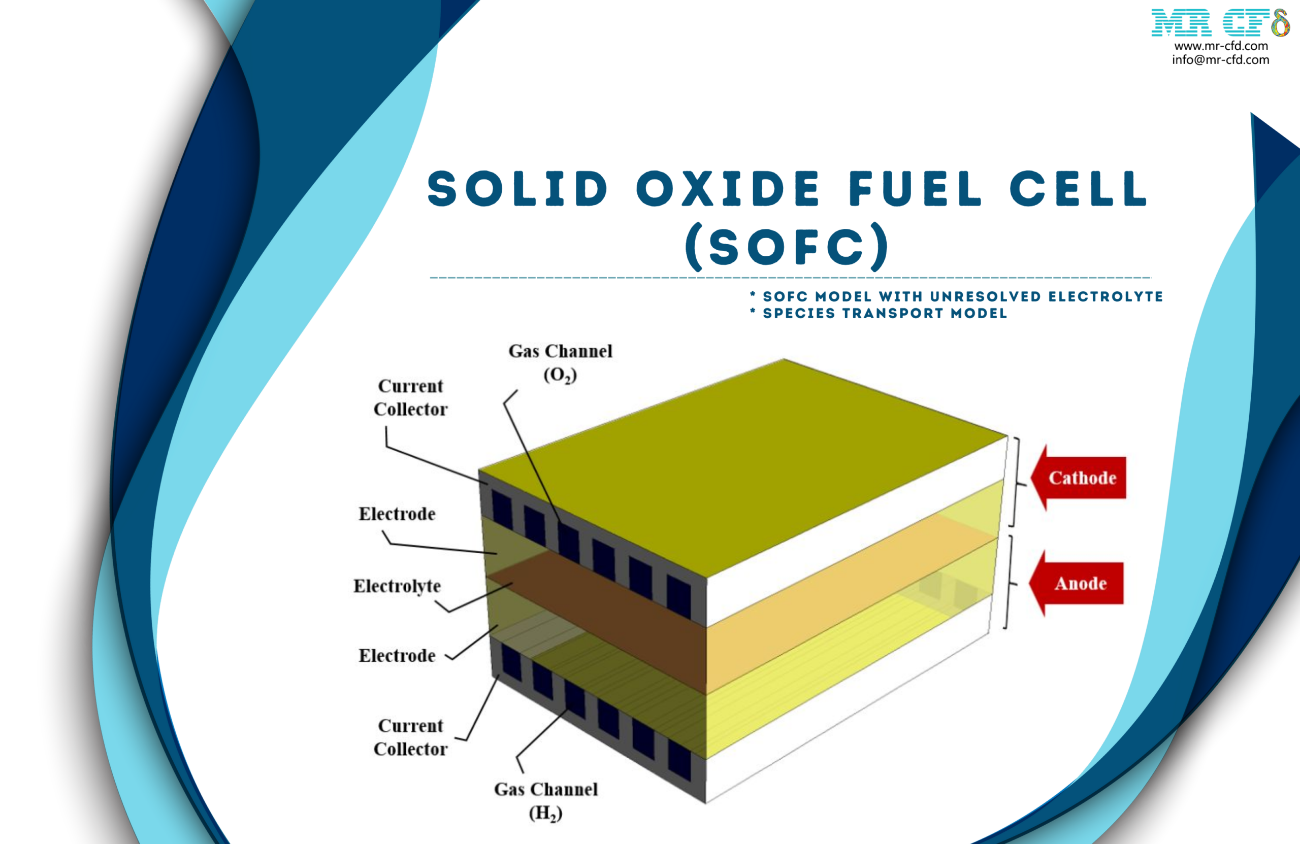
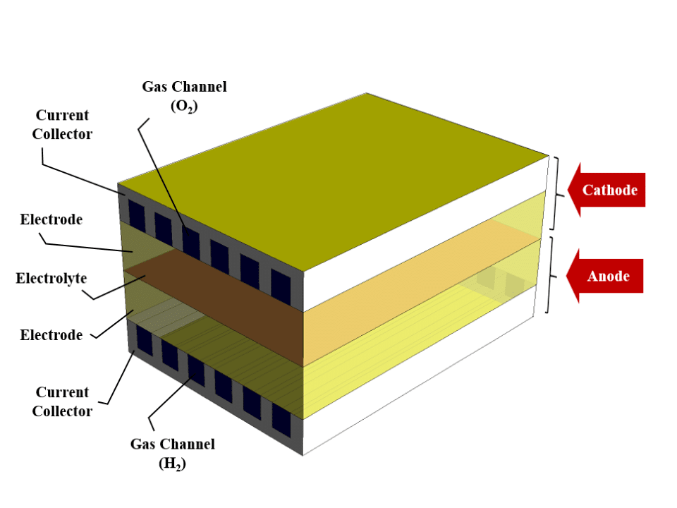
The solid oxide fuel cell consists of two sections, a cathode and an anode. These sections are connected by the electrolyte layer in the central part of the fuel cell. There are two layers of electrode and collector in each cathode and anode section.
The collectors are made of solid material and perform conducting electric current. Inside these current collectors, there is a gas channel. The oxygen (or air) from the gas channel of the cathode collector and the hydrogen (or fuel) from the gas channel of the anode collector enters the fuel cell.
Electrode layers are porous and ion conductive. The oxygen is converted into positive ions by combining with free electrons in the cathode electrode. On the other hand, hydrogen combines with oxygen ions and free electrons to form water in the anode electrode.
The middle electrolytic layer is ceramic and conducts positive oxygen ions. These released electrons create an electric current through the collectors and the circuit connected to the cell.
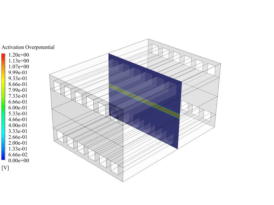
We design the 3D geometry of the fuel cell using Design Modeler software. The computational domain of this model consists of several layers. We define Collectors as solid layers and other layers as fluid layers. Then we mesh this model using ANSYS Meshing software. The mesh type is structured, and the number of cells is 930,240.
SOFC Methodology
We use the “SOFC with unresolved electrolyte” in this project. We load this fuel cell model as an add-on module in ANSYS Fluent software.
The naming of this module has two reasons. First, positive oxygen ions pass through the solid electrolyte layer. Secondly, according to this fuel cell model, the electrolyte layer is not included in the computational domain. We define this layer as an interface (“wall” and “wall shadow”).
When we use this model, a series of source and sink terms are automatically applied, and special materials are defined for each of the layers of the fuel cell.
In this modeling, the electric current in the fuel cell is equal to 10 Amp. For the two terminals of the fuel cell, we define the anode tap as zero voltage (ground voltage) and the cathode tap as the cell’s electric current.
The electrode layers are made of porous materials with a porosity of 0.5. Also, the tortuosity (the ratio of the path between two points to the distance between those two points) of these layers is equal to 2. Also, in the collector and electrode layers, the conductivity (against resistivity) is equal to 0.1 S/m.
As mentioned, hydrogen flow from the anode side and oxygen flow from the cathode side enter the fuel cell and finally, water is formed. So there are several gas species, and several electrochemical reactions take place. Therefore, we use the species transport model to define three volumetric species: hydrogen, oxygen and water.
SOFC Conclusion
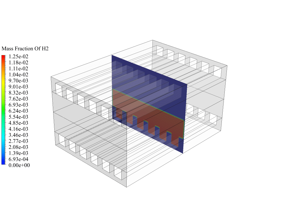
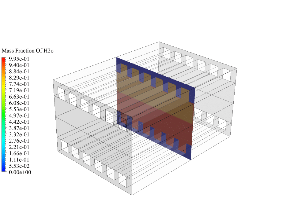
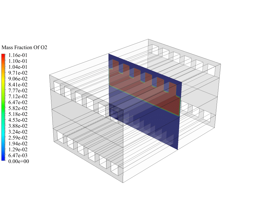
After the calculations, we obtain two-dimensional contours related to the concentration or mass fraction of oxygen, hydrogen and water. These contours correctly confirm the process of electrochemical reactions in the fuel cell.
The results show that oxygen enters from the cathode side and hydrogen enters from the anode side. Initially, there was no water inside the fuel cell, but the results show that water has formed on the anode side of the fuel cell. This means the electrochemical reaction between oxygen, hydrogen and electrons has happened in the fuel cell.
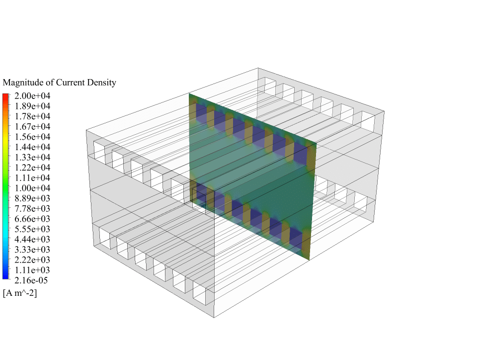
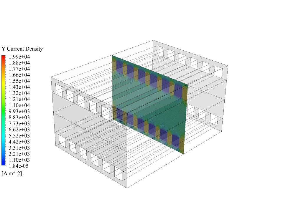
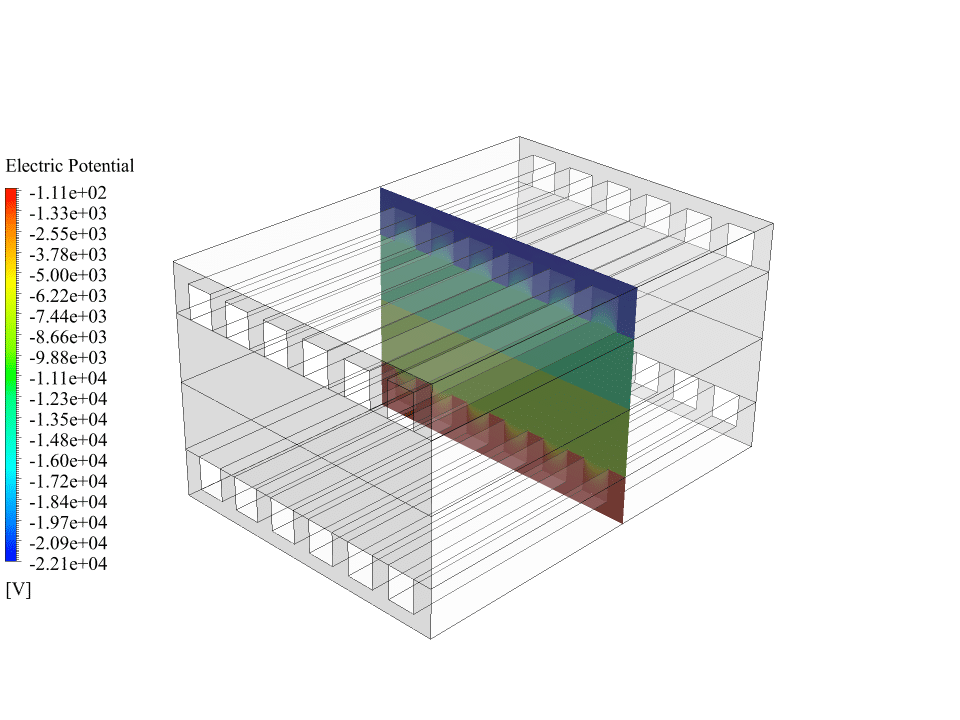
Also, we obtain the contours of electric potential and electric current inside the fuel cell. These contours correctly show the process of generating electric current. There is a potential difference between the cathode and the anode sides, and an electric current is generated inside the fuel cell. So we can say that the solid oxide fuel cell system works correctly.

Marilyne Grady MD –
I successfully completed the SOFC CFD simulation training. The course was detailed and the methodology used gave me a clear understanding of the fuel cell operations, specially the electrochemical reaction process. The tutorials for setting up the various simulations were invaluable. Excellent resource!
MR CFD Support –
Thank you for the kind words! We’re thrilled to know that the SOFC CFD simulation training has provided you with a thorough understanding of fuel cell operations and that our tutorials were helpful. We strive to deliver quality education and it’s rewarding to hear about your positive experience. If you need further assistance in the future or have any additional feedback, please let us know!
Sallie Lakin –
I am thoroughly impressed with the SOFC CFD Simulation using ANSYS Fluent from MR CFD Company. The attention to detail in replicating the electrochemical reactions in the fuel cell is commendable. Especially notable is how the training material enabled the visualization of electric potential and current flow, enhancing understanding of the underlying processes. Bravo on providing such a well-rounded simulation experience!
MR CFD Support –
Thank you very much for your kind feedback! We’re thrilled to hear that you found the SOFC CFD Simulation training to be informative and detailed. It’s always rewarding for us to learn that our efforts to provide a comprehensive learning experience are appreciated. Your understanding and insights into the electrochemical reactions and electric potential differences are precisely what we aim to impart. Thank you for choosing MR CFD Company, and we hope to continue to support your learning journey!
Verona Senger –
I found the detailed explanation of SOFC simulation in ANSYS Fluent really insightful. Your product made it easy to understand the complexities of fuel cell simulations.
MR CFD Support –
Thank you for your positive feedback! We are thrilled to hear that our SOFC CFD Simulation product could help clarify the complexities involved in fuel cell modeling. It’s always our goal to deliver comprehensive and accessible training materials. If you ever have any more questions or need further assistance, please feel free to reach out.
Mrs. Clarabelle Ullrich IV –
The application of SOFC simulation was extremely well-captured by your corporation’s training material on ANSYS Fluent! By the end, my understanding of the complex interactions within a fuel cell greatly improved.
MR CFD Support –
Thank you so much for your kind words! We are thrilled to hear that our training material on SOFC CFD simulation in ANSYS Fluent helped enhance your understanding of fuel cell mechanics. It’s wonderful to know that our aim to deliver comprehensive learning tools has been achieved. If you have any more questions or need further assistance in the future, please don’t hesitate to reach out!
Arno Ward –
Everything is described very well, but could you elaborate on how the electric potential and current results confirm correct function in this system? It seems fascinating that we can visualize the internal workings of such a device.
MR CFD Support –
We appreciate your curiosity! When we look at the results for the electric potential, we observe a distinct potential difference between the anode and the cathode, which precisely demonstrates how a real SOFC would generate an electromotive force. Similarly, the electric current contours depict a continuous current that flows through the collectors and completes the circuit. These physics-based results validate that the numerical simulation successfully mimics the processes occurring inside an actual solid oxide fuel cell, ensuring its correct function in the simulation environment.
Granville Romaguera –
I found the concept of SOFC fascinating! The project appears to provide comprehensive insights into the functioning of solid oxide fuel cells. Are there any suggestions for improving efficiency based on the simulation results?
MR CFD Support –
We appreciate your positive feedback and curiosity. The simulation indeed provides a solid base for understanding the function of SOFCs. Currently, there are not specific suggestions within the project’s scope on efficiency improvements. However, generally, efficiency in SOFCs can be enhanced by optimizing operating temperatures, material properties, reducing resistive losses, and improving the electrode/electrolyte interface. Further research and simulations can explore these avenues in detail.