Spillway (Wide-Edge) with Lateral Slope, Two-Phase Flow, ANSYS Fluent
$120.00 Student Discount
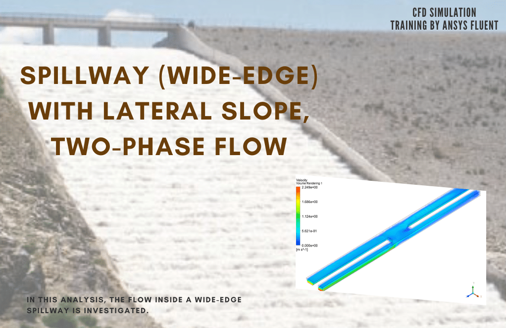
In this analysis, the flow inside a wide-edge spillway is investigated.
Click on Add To Cart and obtain the Geometry file, Mesh file, and a Comprehensive ANSYS Fluent Training Video.To Order Your Project or benefit from a CFD consultation, contact our experts via email ([email protected]), online support tab, or WhatsApp at +44 7443 197273.
There are some Free Products to check our service quality.
If you want the training video in another language instead of English, ask it via [email protected] after you buy the product.
Description
Introduction
A wide-edge spillway is a cascading structure with a long horizontal crown in the direction of the flow so that the error due to the distribution of hydrostatic pressure on it can be neglected due to the acceleration of the radial flow. These overflows operate in such a way that the flow upstream will be subcritical and supercritical on the spillway itself. As a result, a flow control section is created above it. One of the characteristics of such overflows is that in a short distance from the overflow crown, the flow lines are almost parallel.
In this type of spillway, the edge of the spillway is wide enough and has a considerable size compared to other dimensions. The crowns of the overflow edges are wide, horizontal or have a special curvature. Although they are also used to measure discharge, they are mostly used as dam overflows and sometimes as the dam itself (if water is allowed to pass through it) and can be used to store large volumes of water when necessary.
Project description
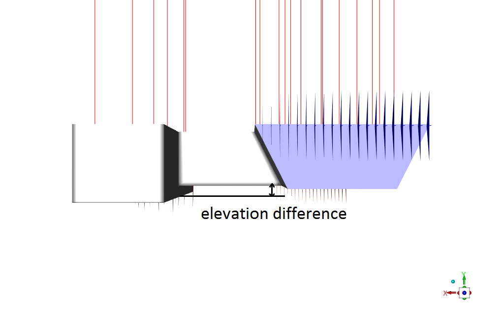
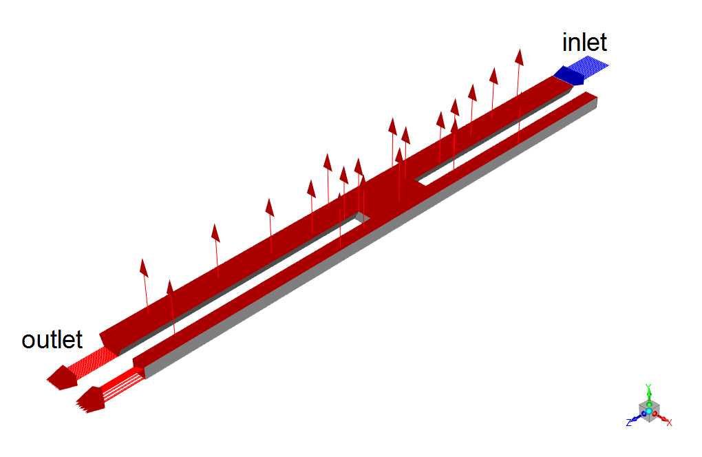
In this analysis, the flow inside a wide-edge spillway is investigated by ANSYS Fluent software. It should be pointed out that there is an elevation difference between the main and sub-channel for reasons like storing a portion of flowing water. The RNG k-epsilon model is used for solving turbulent flow equations. Also, multiphase VOF model is activated to simulate two phases of water and air inside the open channel. The water enters the open channel with a mass flow rate of 65Kg/s and enters the second channel after colliding with middle section of the spillway.
 Geometry and mesh
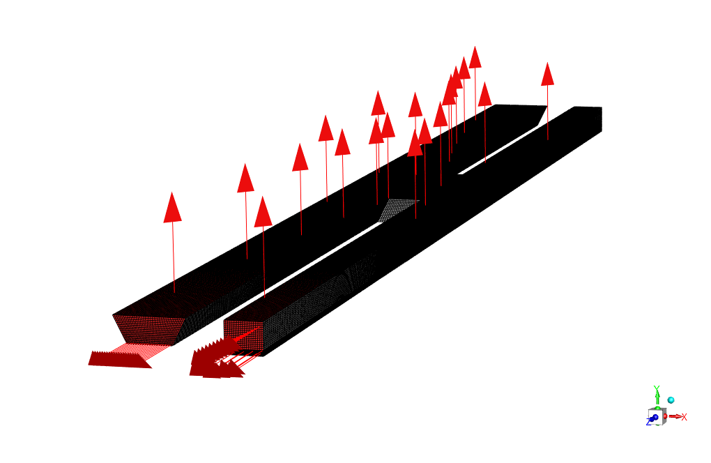
The geometry of this project is designed and meshed inside ANSYS design modeler and meshed in ANSYS meshing. The meshes type used for this geometry is structured and the total number of elements is 981900.

 Spillway CFD simulation settings
The key assumptions considered in this project are:
- Simulation is done using pressure-based solver.
- The present simulation and its results are considered to be steady and do not change as a function time.
- The effect of gravity has been taken into account and is equal to -9.81 in Y direction.
The applied settings are recapitulated in the following table.
| Models | ||
| Viscous model | k-epsilon | |
| k-epsilon model | RNG | |
| near wall treatment | standard wall function | |
| Multiphase | VOF | |
| Primary phase | Air | |
| Secondary phase | water | |
| Boundary conditions | ||
| Inlet | ||
| Water inlet | Type | Mass flow inlet |
| Mass flow rate | 65 Kg/s | |
| Open channel | ||
| Free surface level | 0.08 m | |
| Bottom level | 0 m | |
| Density interpolation method | From neighboring cell | |
| Outlets | Pressure outlet | |
| Walls | ||
| wall motion | stationary wall | |
| Solution Methods | ||
| Pressure-velocity coupling | SIMPLE | |
| Spatial discretization | pressure | PRESTO! |
| momentum | second order upwind | |
| Volume fraction | first order upwind | |
| turbulent kinetic energy | first order upwind | |
| turbulent dissipation rate | first order upwind | |
| Initialization | ||
| Initialization method | Standard | |
| gauge pressure | 0 Pa | |
| velocity | 0 m/s-1 | |
| Turbulent kinetic energy | 1 m2/s2 | |
| Turbulent dissipation rate | 1 m2/s3 | |
| Water volume fraction | 0 | |
Spillway Results
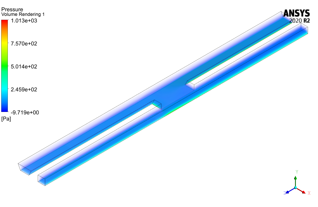
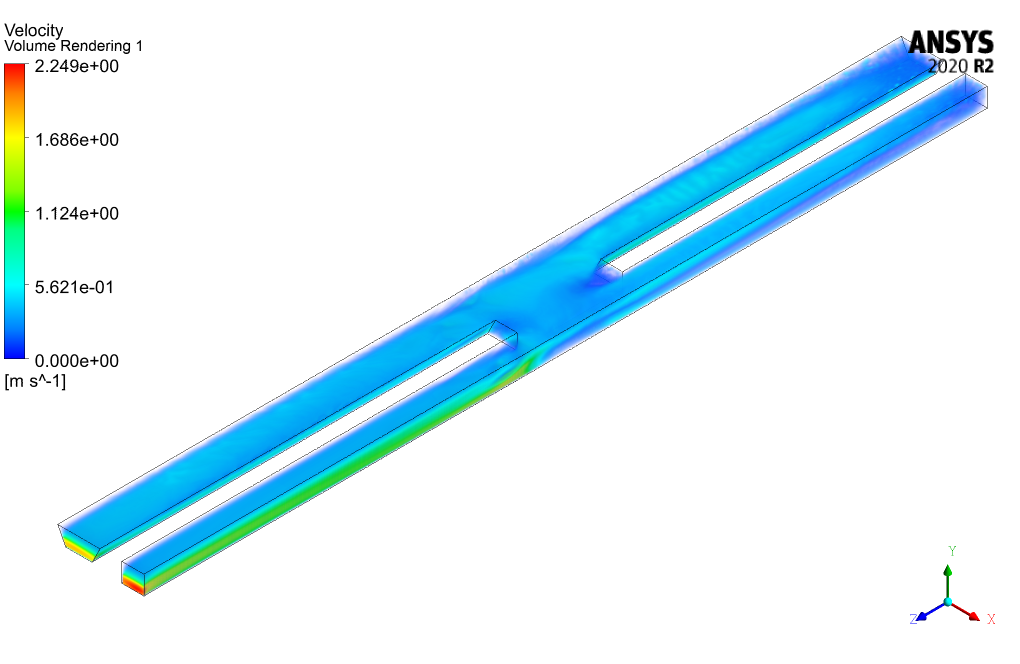
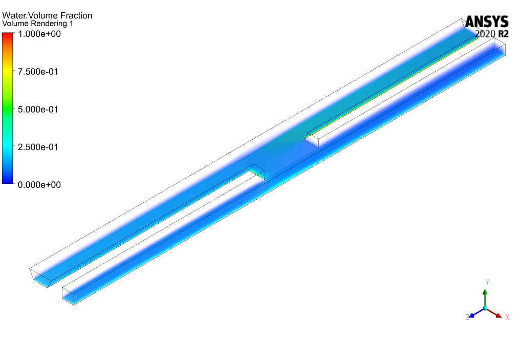
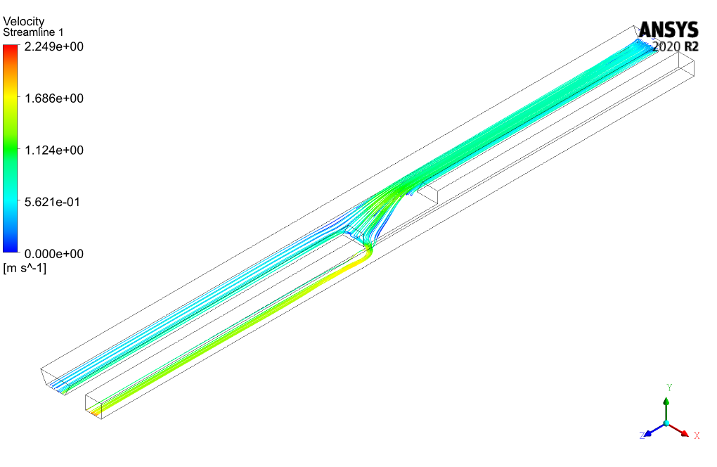
We can see in the water volume fraction contour that due to the existence of height difference and the lack of any inlet flow inside the sub-channel, the water volume fraction has values other than zero in the upper part of the sub-channel. After the simulation process, we extracted and presented 3D contours of pressure, velocity, volume fractions, etc.
 Geometry and mesh
 Spillway CFD simulation settings

Pamela Yundt –
What advantages does the RNG k-epsilon model have when simulating the flow over the wide-edge spillway, compared to the standard k-epsilon model?
MR CFD Support –
The RNG k-epsilon model includes additional terms in the equation that provide a more accurate and detailed turbulence modelling, especially for flows with high strain rates, swirling, and vortices. This leads to improved representation of the complex flow behavior around and over the spillway, such as strong recirculation and flow separation, making it a suitable choice for this CFD simulation.
Stephan O’Connell IV –
Your description of the wide-edge spillway simulation is thoroughly comprehensive! The detailed explanation of the VOF model usage and clear specification of every setting helps envision how the analysis unfolds. It’s insightful to know that the multiphase VOF model captured both water and air phases effectively, and the RNG k-epsilon model tackled the turbulent aspects. The mass flow inlet and detailed boundary conditions align well with real-life engineering problems. Great work on incorporating gravity’s role and choosing appropriate discretization methods for accurate results. The results provide a clear visualization of water fractions and flow behavior over the spillway, which is particularly helpful in understanding the fluid dynamics involved.
MR CFD Support –
Thank you for your kind words and detailed review! We are delighted to hear that the thoroughness and detail of our wide-edge spillway simulation enhanced your understanding of the fluid dynamics involved. It’s gratifying to know that our efforts in accurately setting up and explaining the simulation settings were well-received. Our team always strives for this level of precision and clarity to ensure that our analyses can be easily understood and helpful for users like you. We appreciate you taking the time to recognize our work!
Mrs. Sabryna Donnelly Sr. –
I’m really impressed with the thorough approach to simulating the dynamics of wide-edge spillways with ANSYS Fluent. It’s fascinating to see how the RNG k-epsilon model and VOF are utilized to simulate the water and air phases within the scenario. Kudos on leveraging such detailed meshing to ensure quality results!
MR CFD Support –
Thank you for your kind words and recognition of the effort put into this simulation project. Precise meshing combined with appropriate turbulence and multiphase models are essential in capturing the complex behavior of wide-edge spillways, and we’re glad you appreciate the meticulous work showcased in this analysis. We strive continuously to provide in-depth simulations to assist our users in understanding and solving real-world engineering challenges.
Ahmed Schultz MD –
After reading this thorough analysis, can you tell me what are the main reasons we apply a wide-edge spillway design?
MR CFD Support –
Wide-edge spillways are primarily applied for distributing hydrostatic pressure evenly due to radial flow acceleration, handling subcritical flow upstream and transforming it to supercritical on the spillway, and facilitating flow control. They are useful for passing large volumes of water effectively which is vital in dam overflows and can support water storage when necessary.
Deion Walker –
What a detailed and insightful venture into simulating two-phase flow over a spillway! Seeing how MR CFD Company utilized ANSYS Fluent to mirror such a complex environment is truly remarkable. Their aptitude in describing every element of their project, from the employment of the RNG k-epsilon turbulence model down to the SIMPLE algorithm for pressure-velocity coupling, exemplifies a high degree of mastery. The clear depiction of water volume fraction changes is especially valuable as it reveals critical interactions between the flow’s multiple dynamics. Utilizing a total of 981,900 structured mesh elements only solidifies how precise and thorough this simulation was intended to be. High praise for MR CFD for their meticulous work and for delivering such an educational and thought-provoking product!
MR CFD Support –
Thank you so much for taking the time to leave such a positive and detailed review of our Spillway (Wide-Edge) simulation using ANSYS Fluent. We’re thrilled to learn about your satisfactory experience with the product and are glad that you found the detailed setup and results both engaging and informative. It is always our goal to offer valuable and meticulously crafted educational materials. In case you need further assistance or more learning resources, feel free to reach out to us.
Cathy Hoeger –
The detailed setup for the spillway simulation is impressive! The particular attention to mesh structure and boundary conditions should yield reliable results.
MR CFD Support –
Thank you for the positive feedback! We pride ourselves on providing detailed and precise setup procedures to ensure high-quality simulations for our clients. If you need further assistance or have more inquiries, feel free to contact us.