
Storage Tank containing PCM CFD Simulation, ANSYS Fluent Tutorial
$100.00 Internship
- The problem numerically simulates the performance of phase change materials (PCM) in a storage tank using ANSYS Fluent software.
- We design the 3-D model by the Design Modeler software.
- We Mesh the model by ANSYS Meshing software, and the element number equals 757886.
- We perform this simulation as unsteady (Transient).
- We use the Solidification and Melting model to define phase change materials.
Click on Add To Cart and obtain the Geometry file, Mesh file, and a Comprehensive ANSYS Fluent Training Video.
To Order Your Project or benefit from a CFD consultation, contact our experts via email (info@mr-cfd.com), online support tab, or WhatsApp at +44 7443 197273.
There are some Free Products to check our service quality.
If you want the training video in another language instead of English, ask it via info@mr-cfd.com after you buy the product.
Description
Description
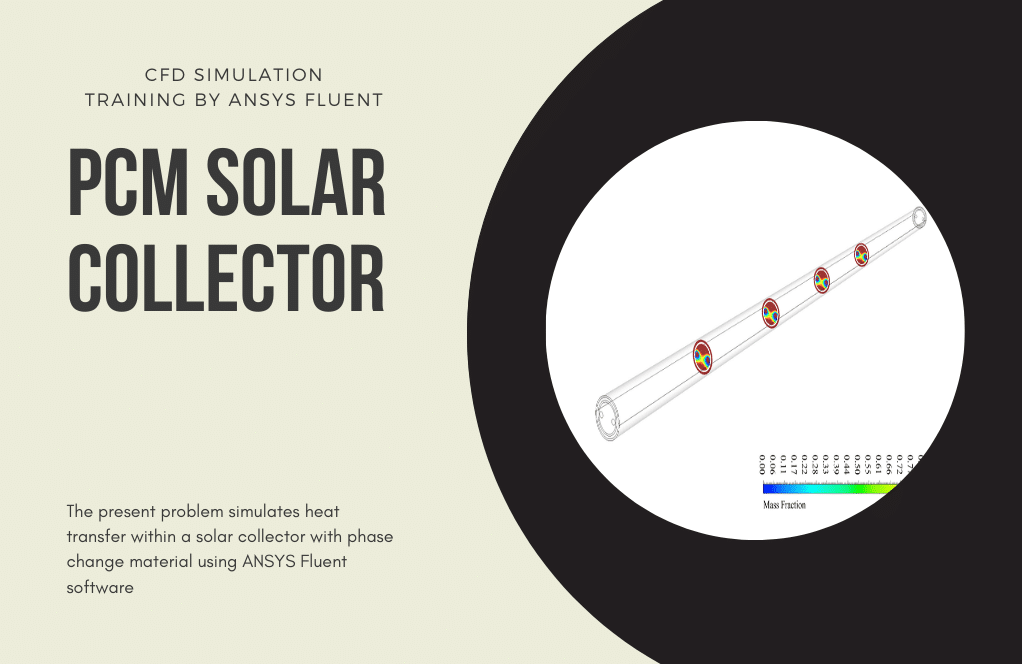
The present problem simulates the performance of phase change materials (PCM) in a storage tank by ANSYS Fluent software. We perform this CFD project and investigate it by CFD analysis.
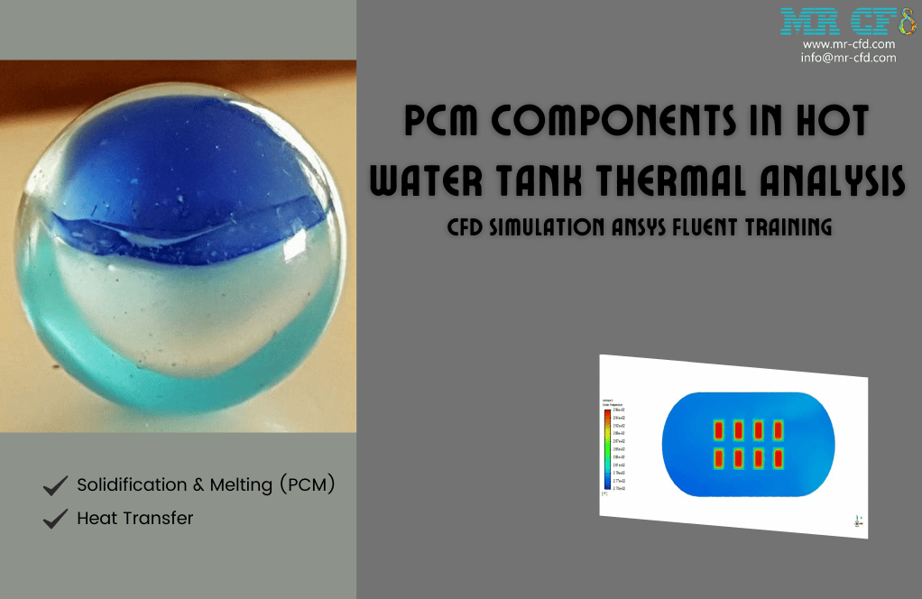
These PCMs are a set of spherical shapes inside the interior of a vertical cylindrical storage tank. The function of these PCMs is that the water flow from the inlet pipe located at the top of the tank enters the internal space with a velocity of 0.1 m/s and a temperature of 343 K.
Then, the water flow comes out of the upper part of the tank. Because the nature of the PCM of the present model is based on the phase change between the two solid and liquid phases, we use the Solidification and Melting model for simulation.
Because the simulation process is transient over time, the simulation time is in the range of 100 s and with a time step size of 1s.
This simulation has been done in several different modes; Thus, two types of PCM of paraffin and sat-g have been performed in spheres with a radius of 4 cm and 5 cm and at two different melting temperatures of 333.15 K and 332 K, respectively.
The present study aimed to investigate the fluid and thermal behavior of the PCMs and to change the ratio of the liquid mass fraction based on the physical dimensions of the phase change materials (radii of the spheres), melting point temperature and material.
This model’s geometry is three-dimensional and designed using ِ Design Modeler software. We use the ANSYS Meshing software to mesh the present model. The mesh type is unstructured, and the element number equals 757886.
PCM Methodology
Since the present problem is related to the simulation of solid-liquid type phase change materials, this model, which is specific to the phase change process between solid and liquid states, has been used.
In the present problem, two different materials have been used paraffin and sat-g. Therefore, these materials are defined by their specific thermophysical properties for Fluent software.
PCM Conclusion
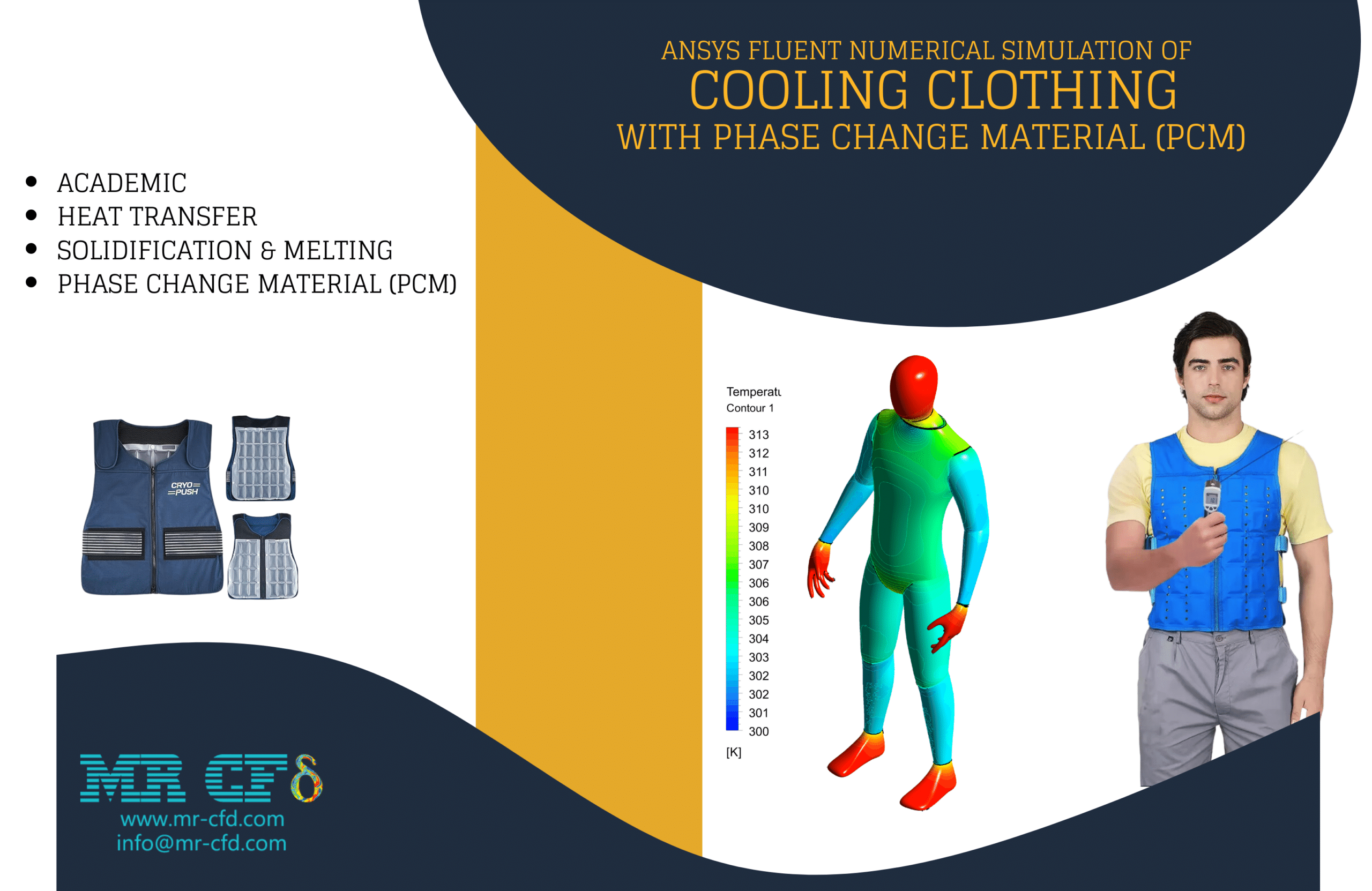
After the solution, we obtain two-dimensional and three-dimensional contours of pressure, temperature, velocity, and liquid and solid mass fractions. These contours are related to the final second of the process. Also, we obtain the graph of the change in the mass fraction of the PCM overtime during the simulation process.
The diagram shows that the longer it takes to dissolve, the more PCM material melts. Up to this point, some PCM material has melted, in return for which the tank temperature has risen. In areas where the temperature is higher, the pressure is lower.
Reviews
You must be logged in to post a review.
Kali Thiel –
How does this simulation model the heat transfer process in the storage tank?
MR CFD Support –
The simulation uses the equations of energy conservation to model the heat transfer process in the storage tank. It can simulate both conduction and convection heat transfer processes, which are critical in the performance of the storage tank.
Evert Bayer –
you are amazing
Jenifer Johns –
The tutorial has been absolutely fantastic! The complex phase change behavior of PCM in a storage tank was illustrated clearly with the contours provided. Seeing the temperature and pressure distribution evolve over the simulation time has been insightful. Thank you MR CFD for a great learning experience!
MR CFD Support –
We’re thrilled to hear that you had such a positive experience with our PCM in a storage tank CFD simulation tutorial! Your understanding and appreciation of the complex behavior illustrated in the simulation is exactly what we aim for. Thank you for taking the time to share your kind words. Be sure to explore our other CFD learning resources for more insights!
Marjorie Champlin –
The storage tank containing PCM simulation was incredible! It helped me understand how PCMs work in real-world applications. The contour representations and the detailed analysis of phase changes were particularly enlightening. The clarity with which the melting temperatures and the effects on fluid dynamics were described is commendable. Marvelous work done by the team!
MR CFD Support –
Thank you very much for your positive review! We are pleased to know that you found the simulation on the storage tank containing phase change materials (PCM) enlightening and valuable. It’s great to hear that the contour representations and phase change analysis added to your understanding of the subject. We appreciate your recognition, and if you have any further inquiries or need more information, do not hesitate to ask – we’re here to help!
Shanie Collins –
Can this simulation be used to evaluate the impact of different tank designs on the performance of the storage system?
MR CFD Support –
Yes, the simulation can be adjusted to evaluate the impact of different tank designs on the performance of the storage system. This includes different tank sizes, shapes, and materials.
Genesis Lowe –
The tutorial mentions two different melting temperatures for the PCM. Could you further explain how these temperatures impact the melting process within the storage tank simulation?
MR CFD Support –
Certainly. The melting temperature of the phase change materials (PCM) has a critical impact on the melting process. The phase change occurs when the PCM reaches its melting temperature. In this simulation, different melting temperatures result in varying rates and profiles of melting. For PCMs with higher melting temperatures, the phase change begins later, as the water at 343 K must transfer more heat for the transition to occur. Conversely, the PCM with the lower melting temperature starts to melt sooner, affecting how and when the PCM absorbs heat, thus influencing the fluid’s temperature throughout the tank and the overall heat storage capacity. The change in liquid mass fraction over time, and related temperature distribution, are key outcomes of the study of these PCMs in the storage tank simulation.
Damon Keebler –
Can this simulation be used to model the performance of the storage system under different operating conditions?
MR CFD Support –
Sure, the simulation can be adjusted to model the performance of the storage system under a variety of operating conditions. This includes different ambient temperatures, heat loads, and operating times.
Bernadine Lockman II –
What was the reason behind choosing paraffin and sat-g as the PCM materials in this simulation?
MR CFD Support –
Paraffin and sat-g were chosen as the PCM materials because they have suitable thermal properties that fit the objectives of the simulation. Paraffin has a desirable phase change temperature and thermal storage capacity which makes it commonly used for thermal management applications. Sat-g is another type of PCM with a different melting point which allows the simulation to compare the performance and efficiency between different materials.
Miss Angelina Predovic DVM –
The tutorial for this Storage Tank containing PCM CFD simulation is pretty impressive! It covered all aspects thoroughly, especially the comparison of different PCMs and their properties. The instructional approach honestly made understanding the phase change process much clearer.
MR CFD Support –
Thank you for your positive review! We take great pride in providing comprehensive tutorials and are thrilled to hear that we could effectively demonstrate the phase change process. Your feedback is much appreciated.
Logan Muller –
Can this simulation be used to model the solidification process of the PCM?
MR CFD Support –
Yes, the simulation can be adjusted to model the solidification process of the PCM. The enthalpy-porosity technique used in this simulation can capture both the melting and solidification processes of the PCM.
Prof. Golden Hahn –
This tutorial was superbly detailed, and I was amazed by the clear distinction shown between the materials’ behaviors! Did they also include guidance on setting up the material properties for each PCM within Fluent?
MR CFD Support –
We’re delighted to hear that our tutorial met your expectations! To address your question, within Fluent, material properties for PCM are set up by defining specific thermophysical variables such as density, specific heat, thermal conductivity, and the temperature at which phase change occurs. These properties are fundamental to accurately simulating the solidification and melting process. Thank you for taking the time to review our product, and we are here to assist if you have any further inquiries!