Turboprop Engine Propeller CFD Simulation
$140.00 Student Discount
- The problem numerically simulates a Turboprop Engine Propeller using ANSYS Fluent software.
- We design the 3-D model with the Design Modeler software.
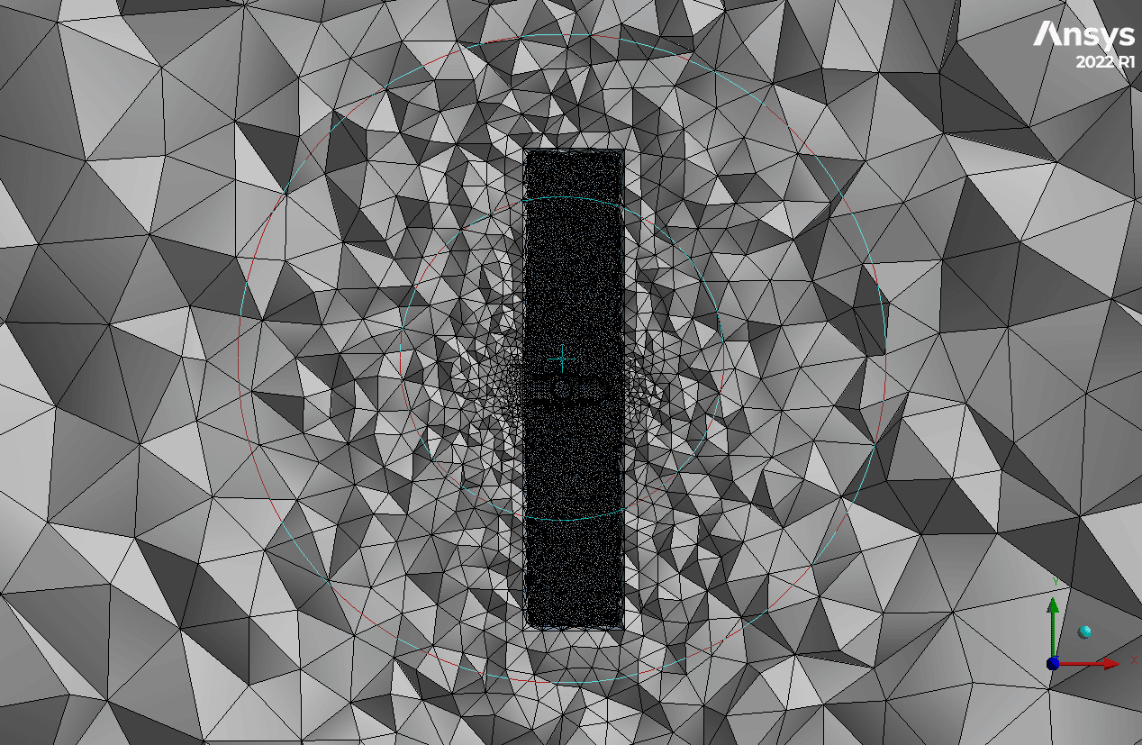
- We mesh the model with ANSYS Meshing software. The element number equals 9,622,423.
- Multiple Reference Frames (Frame Motion) are used to model the rotational motion of the propeller.
- The Density-Based solver is used.
To Order Your Project or benefit from a CFD consultation, contact our experts via email ([email protected]), online support tab, or WhatsApp at +44 7443 197273.
There are some Free Products to check our service quality.
If you want the training video in another language instead of English, ask it via [email protected] after you buy the product.
Description
Turboprop Engine Propeller CFD Simulation, ANSYS Fluent Training
Description
An aircraft propeller, also called an airscrew, converts rotary motion from an engine or other power source into a swirling slipstream which pushes the propeller forwards or backward. It comprises a rotating power-driven hub to which several radial airfoil-section blades are attached so that the whole assembly rotates about a longitudinal axis.
Propellers are most suitable for use at subsonic airspeeds, generally below about 480 mph (770 km/h)
In this case, it is modeled from an A 6-bladed Hamilton Standard 568F propeller on an ATR 72 short-haul airliner and its model with the constant pitch for blades rotation. These propellers are placed in a subsonic flow with a Mach number of 0.4. The speed and pressure changes and the propellers’ speed profile are investigated.
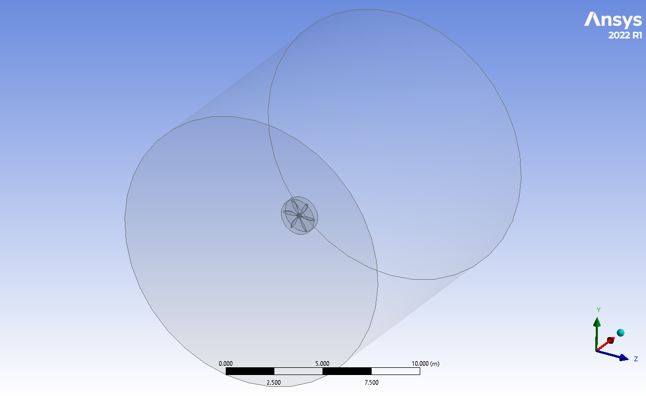
The present model in the 3-D domain of this simulation has been designed in ANSYS Design Modeler. The domain contains a velocity inlet, pressure outlet, and wall for the missile wall and side for the far field.
The meshing of this present model has been generated by ANSYS Meshing software. The mesh grid is unstructured; the total cell number is 9,622,423 elements.
Methodology: Turboprop Engine Propeller CFD Simulation
In this simulation, the Density-Based solver has been used. For modeling turbulence, the k-omega SST model was used. This model simulates the propeller’s rotation with the MRF method.
Conclusion
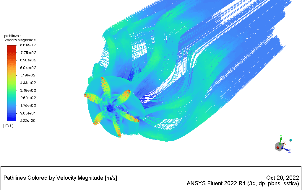
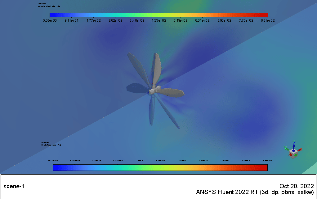
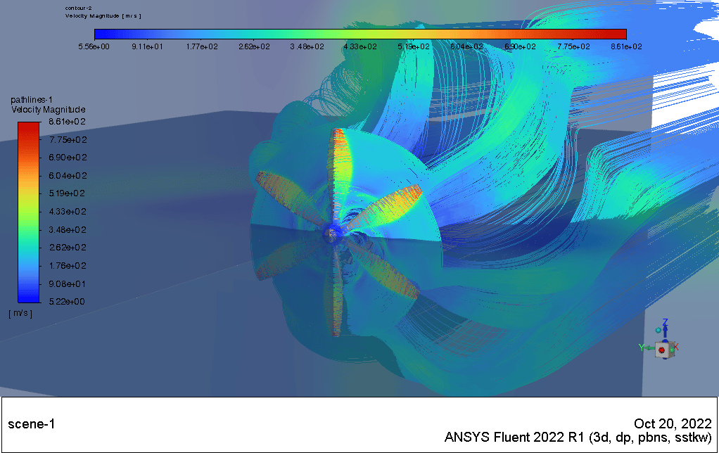
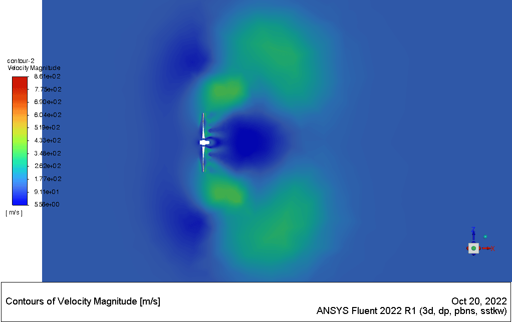
In the simulation results, According to the speed contour, it can be seen how the flow spreads widely in the space after hitting the propeller and its speed increases. Because the propeller does not use the duct fan theorem, it creates larger vortices far from the propeller itself. The shape of these vortices is one of the important topics that can be deduced in this case.
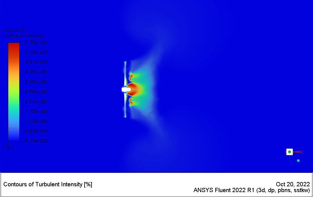
Turbulence contour also shows that the turbulence is at its highest value behind the propellers and decreases as it moves away from the propeller.
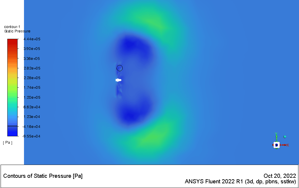
The pressure contour shows the pressure distribution in the front and back of the propeller disc. It also shows how it is spread across the domain concerning speed.
The contours of the flow path show how the flow rotates over the propellers. The way it acts when it comes into contact with the free flow is also apparent.



Trystan Schiller –
I was impressed with how the simulation showed the behavior of the flow after it contacts the propeller. The detailed visualization of vortices and the spread of turbulence provides great insight into the operation of turboprop engines.
MR CFD Support –
Thank you for your positive feedback! We’re thrilled to hear that our CFD simulation has provided valuable insights into propeller flow behavior and aided your understanding of turboprop engine operations. If you have further interest in our CFD products or need more information, please feel free to reach out.
Lulu Torphy –
Loved the detail in this simulation, particularly how it captured turbulence changes behind the propellers. Learning about the aerodynamics of turboprop engines has never been this intuitive. Can’t wait to test this out in my own design projects!
MR CFD Support –
Thank you for your positive feedback! We’re thrilled to hear that our simulation has provided you with valuable insights into turboprop engine aerodynamics. We’re always here to support passionate learners like you in your design endeavors. Don’t hesitate to reach out if you need any more assistance. Keep flying high with your projects!
Isabell Prohaska DDS –
I am absolutely impressed with the detailed analysis of propeller performance using CFD! Great to see the speed, pressure, and turbulence being tackled so comprehensively.
MR CFD Support –
Thank you for your kind words! We’re thrilled to hear you’re impressed with the turboprop engine propeller simulation and that you recognize the depth of analysis our product provides. We strive to deliver comprehensive training that our customers find valuable.
Abdiel Harris –
This CFD simulation of the Turboprop Engine Propeller is quite impressive in detail! I appreciate the extensive work done on the air flow dynamics, especially the way vortices form behind the propellers and their distribution across the domain. It sounds like this training offers valuable insights, which can be particularly beneficial for aerospace engineering applications or even for educational purposes.
MR CFD Support –
Thank you for your kind words! We’re pleased to hear that our Turboprop Engine Propeller CFD Simulation was beneficial and insightful for you. MR CFD Company is dedicated to delivering in-depth and applicable CFD training for various applications, including aerospace engineering. Your feedback is very important to us, and we look forward to providing more quality learning products that meet your expectations.
Mr. Miller Heathcote –
I’m fascinated by how the simulation captures the vortices created by the propeller. Can you tell me more about the accuracy of the turbulence modeling in the context of this simulation and any validations done against real-world data?
MR CFD Support –
In this simulation, the k-omega SST turbulence model was used, which is highly accurate for capturing the vortex shedding and turbulence intensity for external flows around complex geometries like aircraft propellers. Validation of the model would involve comparing the computed results with experimental data such as wind tunnel testing of a propeller or perhaps flight test data. Unfortunately, specific details about validation against real-world data are not provided in the description you have, but that’s a common step in a robust simulation process to ensure accuracy.
Adeline Klein Sr. –
Wonderful training product! As an aviation enthusiast, using the provided methodology I was able to observe the complex interactions of flow around the propeller blades. Excellent use of the k-omega SST model in showing the vortex shapes and turbulence distribution!
MR CFD Support –
Thank you for your kind words! We’re thrilled to hear you appreciated the simulation’s depth and the detailed analysis it provided on the propeller’s aerodynamics. If you have any further feedback or need additional resources in aviation simulation, feel free to reach out!
Orpha Beier –
I followed the training for the Turboprop Engine Propeller CFD Simulation, and the content was very detailed. The step-by-step approach made the complex process much easier to understand, and it was fascinating to see the speed profiles and turbulence contours behind the propeller blades. Great work on this tutorial!
MR CFD Support –
Thank you for your positive feedback! We are thrilled to hear that our tutorial on Turboprop Engine Propeller CFD Simulation was helpful to you. We always strive to make our training materials comprehensive and easy to understand, and it’s rewarding to know that the detailed explanation of the speed profiles and turbulence contours contributed to your learning experience. If there’s anything more we can assist with, please do not hesitate to reach out!
Danika Barrows PhD –
This simulation of the Turboprop Engine Propeller looks very comprehensive. I’m impressed, especially with the way it tackles complex aspects like the vortices formed behind the propeller.
MR CFD Support –
Thank you for your positive review of the Turboprop Engine Propeller CFD Simulation! We’re thrilled to hear that our simulation meets your expectations and provides a detailed examination of the aerodynamic phenomena. Should you have any further questions or need additional information, please feel free to reach out.
Dr. Adolphus Mueller PhD –
The simulation results of the turboprop engine propeller are truly impressive! It’s fascinating to see how the flow interacts with the propeller. An excellent demonstration of fluid dynamics in action!
MR CFD Support –
Thank you for your kind words! We’re delighted to hear that you found the simulation results for the turboprop engine propeller informative and captivating. Fluid dynamics is indeed a fascinating field, and we’re glad we could provide you with insights through our CFD simulation. If you have any further questions or need more information about our products, feel free to ask. We appreciate your feedback!
Dr. Patrick Wehner IV –
I’m astounded by how the simulation captures the propeller’s effect on the airflow! It’s really cool seeing those vortices visualized. The detail and precision speak volumes about the potential of your training materials for practical understanding.
MR CFD Support –
Thank you for the positive feedback! We’re delighted to hear that the simulation met your expectations and provided a clear visualization of the propeller’s influence on airflow. Appreciating the detail and precision in our training materials reaffirms our commitment to offering valuable learning experiences. If you have any further questions or need additional training materials, we’re here to help!
Amir Smith –
The training provided me with an excellent understanding of performing a CFD simulation for a turboprop engine propeller. The contours and pathlines illustrated how the propeller influences the surrounding air flows, which was particularly enlightening. Working through this simulation, I gained practical experience with setting up and interpreting airflow dynamics, which will assist me greatly in similar future aerospace projects.
MR CFD Support –
We appreciate your positive feedback! It’s wonderful to hear that the turboprop engine propeller CFD simulation was beneficial for your understanding of airflow dynamics. If you have any further questions or need assistance with other simulations, please don’t hesitate to ask. Thank you for choosing our training materials for your aerospace projects!
Alvis Dare V –
The explanation of the propeller CFD simulation is insightful. I’m impressed by the detail and complexity of the model—especially how it captures the flow distribution and vortex formation.
MR CFD Support –
Thank you for your positive feedback on our Turboprop Engine Propeller CFD Simulation. We work hard to provide thorough and detailed simulations that are useful for industry professionals and researchers alike. Your recognition of our efforts is much appreciated!