
Vertical Heat Exchanger, ANSYS Fluent CFD Simulation
$80.00 $8.00 Internship
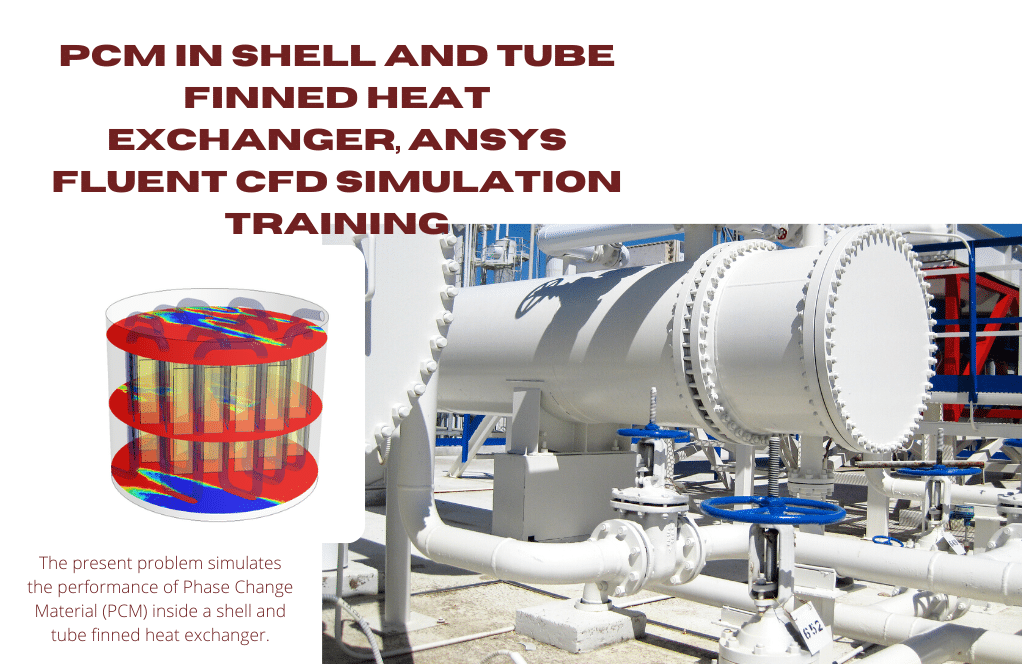
The present problem simulates heat transfer in a three-dimensional vertical heat exchanger using ANSYS Fluent software.
Click on Add To Cart and obtain the Geometry file, Mesh file, and a Comprehensive ANSYS Fluent Training Video.To Order Your Project or benefit from a CFD consultation, contact our experts via email (info@mr-cfd.com), online support tab, or WhatsApp at +44 7443 197273.
There are some Free Products to check our service quality.
If you want the training video in another language instead of English, ask it via info@mr-cfd.com after you buy the product.
Description
Vertical Heat Exchanger, ANSYS Fluent CFD Simulation Training
The present problem simulates heat transfer in a three-dimensional vertical heat exchanger using ANSYS Fluent software. This heat exchanger is designed vertically; In this way, the flow of cold fluid enters from the upper part of one of the sidewalls of the heat exchanger and exits from the lower portion of the sidewall in front of it; While the flow of hot fluid from the floor of the heat exchanger enters vertically and upwards and exits the ceiling. Cold fluid flow enters the heat exchanger at a velocity of 8.88 ms-1 and temperature of 239.15 K through 30 vents. Hot fluid flow enters the heat exchanger at a velocity of 15.23 ms-1 and temperature of 393.15 K through 30 vents.
The hot fluid defined in the model has a density of 0.898 kg.m-3, a specific heat capacity of 1013 j.kg-1.K-1, a thermal conductivity of 0.0238 Wm-1.K-1, and a viscosity of 1.7894 e-5. The cold fluid defined in the model has a density equal to 1.205 kg.m-3, specific heat capacity equal to 1005 j.kg-1.K-1, thermal conductivity equal to 0.0257 Wm-1.K- 1, and the viscosity is equal to 1.7894e-5. Also, all the inner walls of the heat exchanger and the outer wall of the heat exchanger are made of aluminum, and the external body of the heat exchanger has a thermal insulation boundary condition.
Geometry & Mesh
The present model is designed in three dimensions using Design Modeler software. The model is related to a heat exchanger in the shape of a vertical rectangular cube with a rectangular cross-section with a length and width of 1 m and 1.5 m and 3 m. The cold flow inlet of the heat exchanger is in the upper part of one of its sidewalls, which consists of 30 narrow holes, and the hot flow inlet is located on the floor of the heat exchanger, which has 30 tiny holes. Each cold flow inlet has a width of 0.015 m and a length of 1 m; While each of the hot flow inlet vents has a width of 0.035 m and a length of 1 m. The cold flow outlet is in the lower part of the sidewall in front of its inlet, and the hot flow outlet is located on the roof of the heat exchanger.

We carry out the model’s meshing using ANSYS Meshing software, and the mesh type is unstructured. The element number is 939600. The following figure shows the mesh.

CFD Simulation
We consider several assumptions to simulate the present model:
- We perform a pressure-based solver.
- The simulation is steady.
- The gravity effect on the fluid is ignored.
The following table represents a summary of the defining steps of the problem and its solution:
| Models | ||
| Viscous | k-epsilon | |
| k-epsilon model | standard | |
| near wall treatment | standard wall functions | |
| Energy | On | |
| Boundary conditions | ||
| Inlet – Cool | Velocity Inlet | |
| velocity magnitude | 8.88 m.s-1 | |
| temperature | 293.15 K | |
| Inlet – Ho | Velocity Inlet | |
| velocity magnitude | 15.23 m.s-1 | |
| temperature | 393.15 K | |
| Outlet – Cool & Hot | Pressure Outlet | |
| gauge pressure | 0 pascal | |
| Inner Wall | Wall | |
| wall motion | stationary wall | |
| thermal condition | coupled | |
| wall thickness | 0.002 m | |
| Outer Wall | Wall | |
| wall motion | stationary wall | |
| heat flux | 0 W.m-2 | |
| Methods | ||
| Pressure-Velocity Coupling | SIMPLE | |
| Pressure | second order | |
| momentum | second order upwind | |
| turbulent kinetic energy | first order upwind | |
| turbulent dissipation rate | first order upwind | |
| energy | second order upwind | |
| Initialization | ||
| Initialization methods | Hybrid | |
Results & Discussions
At the end of the solving process, two-dimensional and three-dimensional contours related to pressure, speed, and temperature are obtained. The results show that the heat transfer is allowed so that the cold part of the heat exchanger increases the temperature and the hot part of the heat exchanger decreases the temperature.
Reviews
You must be logged in to post a review.

Brando Pfeffer DDS –
Such an insightful and thorough explanation of the Vertical Heat Exchanger simulation! It’s evident that a lot of thought has gone into the design and execution of the computational model. The details on geometry, mesh, boundary conditions and solver setup were particularly useful. Well done on successfully capturing the heat exchange process.
MR CFD Support –
Thank you for your positive feedback! We’re glad to hear that the details provided on the Vertical Heat Exchanger simulation were helpful and met your expectations. Our team strives to offer comprehensive and understandable resources, and your comments affirm our efforts. Don’t hesitate to reach out if you ever need more information or additional assistance.
Clementina Lemke –
I’ve been impressed by the detailed results! Can you provide any information on how effective this heat exchanger model is, perhaps in terms of thermal efficiency?
MR CFD Support –
Thank you for your positive feedback! We’re delighted to hear that you found our simulation results detailed and informative. Unfortunately, the training information provided does not include specific numerical values or assessments of thermal efficiency. However, such evaluations typically include the heat transfer rate, the temperature difference between incoming and outgoing fluids, and the heat exchange surface area. If you are interested in a more comprehensive efficiency analysis, we suggest consulting the final CFD report or performing additional simulations to quantify the exact efficiency of the heat exchanger model.
Terry Kertzmann Jr. –
I am amazed at how well the contours in the simulation outputs depict the temperature distribution, especially as the temperature of the cold side increases and the hot side decreases. This clear visualization has helped me to understand the efficiency of the heat exchanger design. Well done to the team!
MR CFD Support –
Thank you so much for your feedback! We’re delighted to hear that the simulation results provided you with a clear understanding of the heat exchanger’s performance. Our team works hard to provide accurate and accessible visualizations to aid in comprehending complex concepts, and it’s rewarding to know when it’s appreciated. If you ever have further inquiries or require assistance, don’t hesitate to reach out. Thank you for choosing our learning products!
Ms. Stephanie Carroll –
This training content was comprehensive and insightful. I appreciate the detailed explanation of boundary conditions and the mesh model visualization. The practical application of CFD principles in a functioning heat exchanger provided a deeper understanding of thermal dynamics in engineering systems.
MR CFD Support –
Thank you for your feedback! We are delighted to hear that you found the training content for the vertical heat exchanger simulation both comprehensive and insightful. It’s our aim to provide useful and detailed materials to enhance the learning experience. If you have any more questions or need further clarifications, please don’t hesitate to ask.
Miss Amaya Hermiston PhD –
This was a fantastic learning experience as I navigated through the complexities of setting up and solving a thermal problem on ANSYS Fluent. The details on the boundary settings, the method of initialization, and the step-by-step simulation guide were perfect for understanding vertical heat exchange processes. I particularly appreciate the attention to detail in wall conditions and the coupling of pressure-velocity aspects. The content provided the right balance of theory and practical example!
MR CFD Support –
Thank you so much for your positive feedback! We’re thrilled to hear that you found the simulation guide helpful and informative. It’s wonderful to know that our efforts to provide detailed and balanced educational content are appreciated by our customers. We look forward to continuing to support your learning journey with our products!
Armando Hoppe –
The training for the vertical heat exchanger simulation was fantastic! It’s clear that a lot of thought went into designing a realistic model, and the results I’ve seen in the velocity, temperature and pressure contours are highly insightful for understanding heat transfer within this system.
MR CFD Support –
We are absolutely thrilled to hear that you enjoyed the training and found the simulation results insightful. At MR CFD, we strive to provide comprehensive and realistic simulations to aid in the understanding of complex systems. Thank you for taking the time to share your positive experience! If you have any further questions or need assistance on your CFD journey, please do not hesitate to reach out to us.