
VTOL Jet Engine Thrust Force Generation, CFD Simulation
$150.00 $90.00 HPC
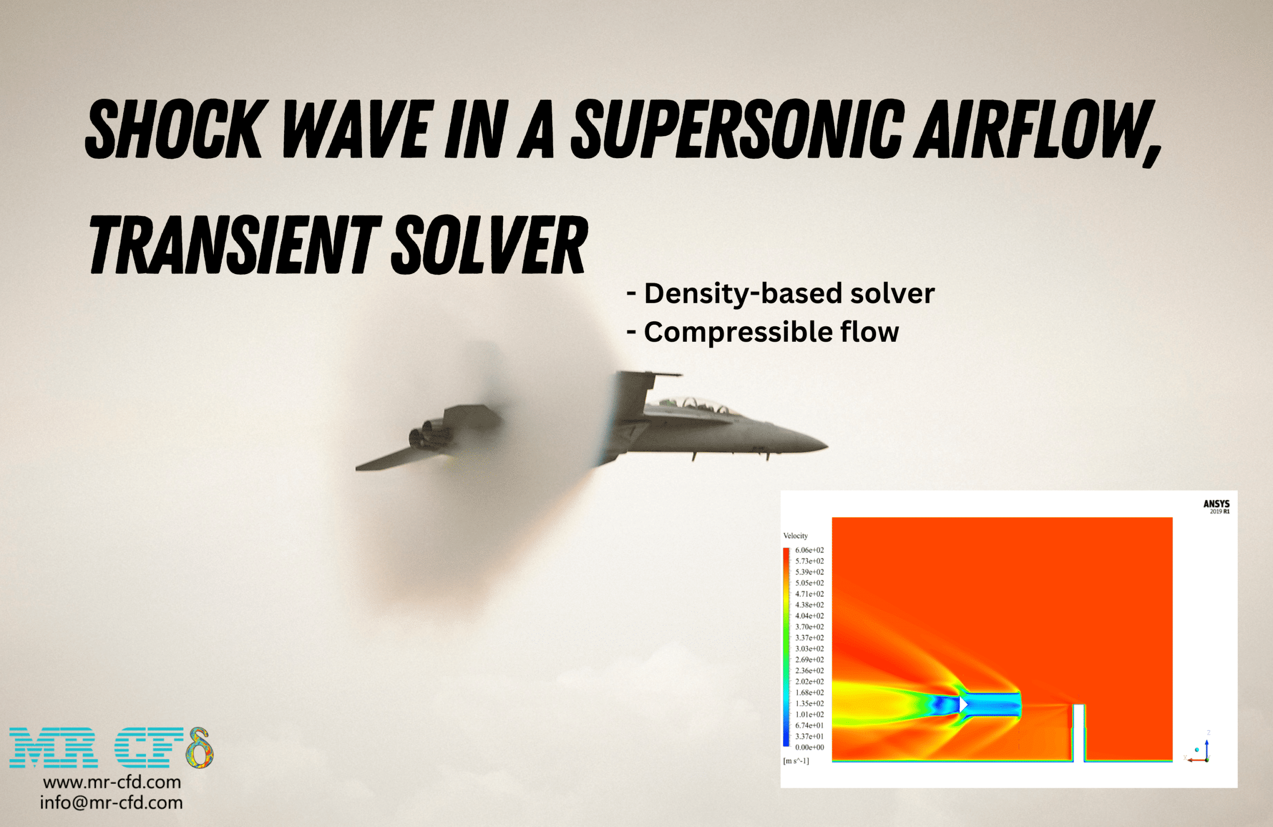
- This report presents a simulation that investigates the thrust generation of a VTOL (Vertical Take-Off and Landing) jet engine operating in vertical mode.
- The aerodynamic performance and thrust force produced by a rotating fan within a bent pipe configuration were analyzed.
- The 3D geometry of the bent pipe with fan was created using ANSYS SpaceClaim software.
- A high-quality unstructured mesh with boundary layer refinement was generated using ANSYS Meshing software.
- Appropriate turbulence model settings and boundary conditions were applied to correctly simulate the rotating fan dynamics and the resulting thrust force generation.
To Order Your Project or benefit from a CFD consultation, contact our experts via email (info@mr-cfd.com), online support tab, or WhatsApp at +44 7443 197273.
There are some Free Products to check our service quality.
If you want the training video in another language instead of English, ask it via info@mr-cfd.com after you buy the product.
Description
VTOL Jet Engine Performance: Investigating Thrust Force Generation in Bent Pipe Configuration
Understanding the aerodynamic performance of VTOL propulsion systems and VTOL jet engines is critical for modern aerospace applications. The ability to generate sufficient thrust in vertical mode determines the feasibility and efficiency of aircraft capable of vertical take-off and landing operations. In such configurations, the flow path geometry, fan characteristics, and operating conditions directly influence the thrust production. The interaction between the rotating fan and the complex bent pipe geometry creates intricate flow patterns that must be accurately predicted to optimize system performance. Therefore, the goal of this study is to simulate the three-dimensional flow field within a VTOL jet engine configuration and to quantitatively determine the thrust force generated by a fan rotating at 15,000 RPM.
Using ANSYS Fluent software, a comprehensive numerical investigation was conducted to analyze the coupled fluid dynamics and rotating machinery effects. The bent pipe geometry with non-circular cross-section was designed in ANSYS SpaceClaim, and a high-fidelity unstructured mesh was generated using ANSYS Meshing (5,740,271 elements) with boundary layer refinement near the fan surfaces to ensure accurate resolution of the velocity gradients and turbulent flow structures. The study evaluates both the qualitative flow field characteristics and the quantitative thrust force, providing valuable engineering data for the design and optimization of VTOL propulsion systems.
Methodology
A pressure-based, steady-state solver was employed to capture the fully developed flow field within the engine configuration. Air was used as the working fluid, with density modeled using the ideal gas equation of state to account for compressibility effects. The energy equation was enabled to model heat transfer and temperature variations throughout the domain. The realizable k-epsilon turbulence model was selected due to its superior performance in capturing rotating flows, separated flows, and flows with strong streamline curvature—all characteristics present in this configuration. The fan rotation at 15,000 RPM was implemented using appropriate moving reference frame method (MRF) to accurately represent the momentum addition to the fluid. Appropriate boundary conditions were specified at the inlet, outlet, and wall surfaces to simulate realistic operating conditions and ensure proper flow development through the bent pipe geometry.
Results and Conclusion
From the simulation, the following results are obtained:
- The velocity magnitude contours show flow acceleration through the fan region, with velocities increasing from near-zero at the inlet to maximum values of approximately 884 m/s at the outlet section, demonstrating the momentum addition by the rotating fan.
- Static pressure distribution reveals a pressure rise across the fan region, with values ranging from approximately -76.8 kPa to 52.0 kPa, indicating the work input from the rotating machinery to the fluid.
- Static temperature contours show temperature variations throughout the domain, ranging from approximately 228 K to 646 K, with elevated temperatures concentrated near the fan blades and in the outlet region due to aerodynamic heating and compression effects.
- The total thrust force generated by the system was calculated to be 5945.43 N based on the general thrust equation, which accounts for momentum flux and pressure contributions at the inlet and outlet boundaries.
You must be logged in to post a review.


Reviews
There are no reviews yet.