Well Drilling, Mud and Sand Separator, ANSYS Fluent CFD Simulation Training
$140.00 Student Discount
The present problem simulates well drilling and sludge separation using ANSYS Fluent software.
Click on Add To Cart and obtain the Geometry file, Mesh file, and a Comprehensive ANSYS Fluent Training Video.To Order Your Project or benefit from a CFD consultation, contact our experts via email ([email protected]), online support tab, or WhatsApp at +44 7443 197273.
There are some Free Products to check our service quality.
If you want the training video in another language instead of English, ask it via [email protected] after you buy the product.
Description
Well Drilling Project Description
The present problem simulates well drilling and sludge separation using ANSYS Fluent software. In this simulation, a cylindrical hole is considered a well, inside which a rotating body in the shape of a cylinder is placed. Inside the cavity, a Non-Newtonian material for drilling operations flows; So that the mud particles inside it are mixed. With its rotational motion at 100 rpm, this rotating cylindrical body can separate the mud particles mixed in the non-Newtonian fluid and raise them. Therefore, the Eulerian multiphase model has been used to define the flow in the well. The primary phase of this multiphase flow is related to the same non-Newtonian fluid called CMC, and its second phase is related to mud particles called drilling.
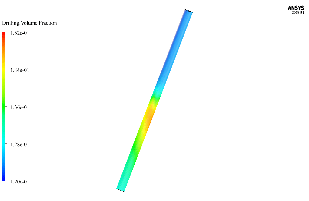
Eulerian multiphase model in cases such as concentration of more than 10 percent of dispersed particles in the base fluid, pneumatic transitions for liquid and solid flows, the slurry flows in a liquid and solid, deposition as two-phase liquid and solid flows, etc. is used. In this simulation, the base fluid within the computational area has a volume fraction equal to 0.87, and the mud solution particles have a volume fraction equal to 0.13. Fluids are also divided into two categories of Newtonian and non-Newtonian fluids in terms of viscosity. The viscosity of a fluid is a parameter that indicates the resistance of that fluid to flow. Newtonian fluids follow Newton’s law of viscosity (shear stress in a Newtonian fluid changes linearly with strain rate).
Project Description
Also, their viscosity depends only on the temperature and pressure of the fluid, and by applying force to them in constant temperature and pressure, their viscosity does not change; Non-Newtonian fluids, on the other hand, are fluids that do not follow Newton’s law of fluids, and their viscosity changes with the application of force. The fluid CMC as the primary phase has a density of 1271.477 kg.m-3, and its viscosity is defined as non-Newtonian, which is according to the Herschel-Bulkley rule; While the soluble particles of mud in the Non-Newtonian fluid also have a density equal to 2000 kg.m-3 and a viscosity equal to 0.00111 kg.m-1.s-1.
Geometry & Mesh
The present model is designed in three dimensions using Design Modeler software. The model is related to two eccentric cylindrical walls. These two cylinders have a length equal to 10 m, and the diameter of the inner cylinder is equal to 0.128 m, and the diameter of the outer cylinder is equal to 0.444 m.
We carry out the model’s meshing using ANSYS Meshing software. The mesh type is unstructured. The element number is 179820. The following figure shows the mesh.
CFD Simulation
We consider several assumptions to simulate the present model:
- We perform a pressure-based solver.
- The simulation is unsteady.
- The gravity effect on the fluid is equal to -9.81 m.s-2. So that according to the angle of 30 degrees of the model with the direction of gravity, the amount of gravity acceleration is equal to 4.9 and 8.5 in the X and Z directions, respectively.
The following table represents a summary of the defining steps of the problem and its solution:
| Models | ||
| Viscous | k-omega | |
| k-omega model | standard | |
| Multiphase Model | Eulerian | |
| number of eulerian phases | 2 (cmc & drilling) | |
| formulation | implicit | |
| Boundary conditions | ||
| Inlet | Velocity Inlet | |
| gauge pressure | 0 Pascal | |
| velocity magnitude – cmc | 0.357 m.s-1 | |
| volume fraction – cmc | 0.87 | |
| velocity magnitude – drilling | 0.357 m.s-1 | |
| volume fraction – drilling | 0.13 | |
| Outlet | Pressure Outlet | |
| gauge pressure | 0 pascal | |
| Inner Wall | Wall | |
| wall motion | moving wall | |
| motion | rotational (z-axis) | |
| speed | 100 rpm | |
| Outer Wall | ||
| wall motion | stationary wall | |
| Methods | ||
| Pressure-Velocity Coupling | Phase Coupled SIMPLE | |
| Pressure | PRESTO | |
| momentum | first order upwind | |
| turbulent kinetic energy | first order upwind | |
| specific dissipation rate | first order upwind | |
| volume fraction | first order upwind | |
| Initialization | ||
| Initialization methods | Standard | |
| gauge pressure | 0 Pascal | |
| velocity – cmc | 0.357 m.s-1 | |
| velocity – drilling | 0.357 m.s-1 | |
| volume fraction – drilling | 0.1 | |
Well Drilling Results & Discussions
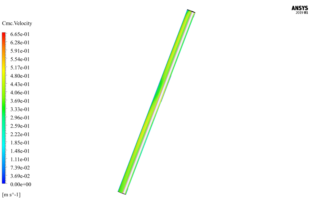
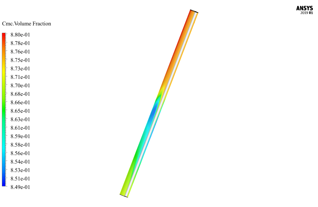
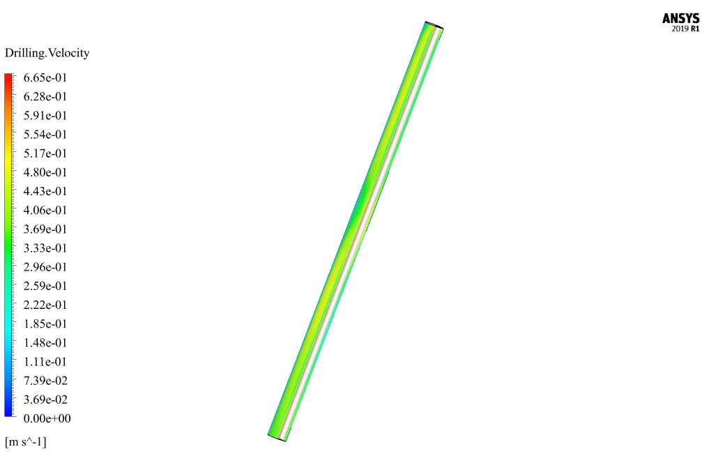
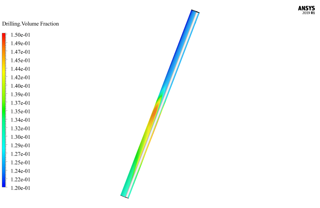
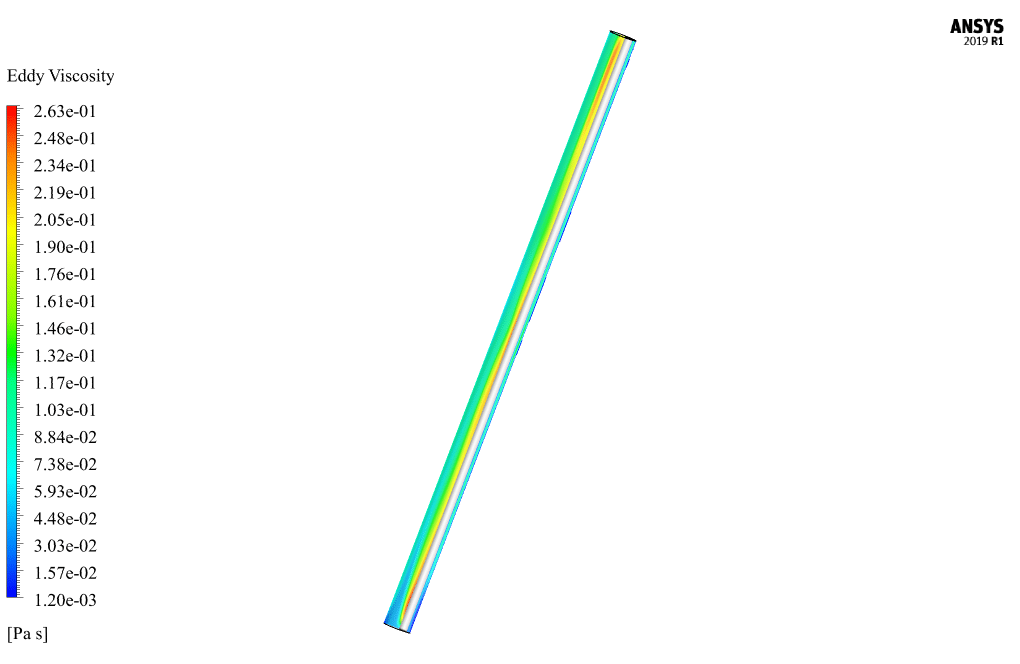
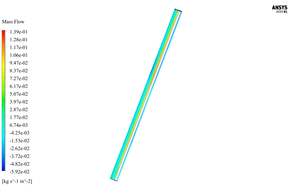
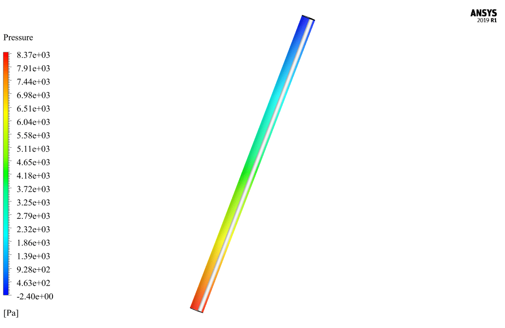
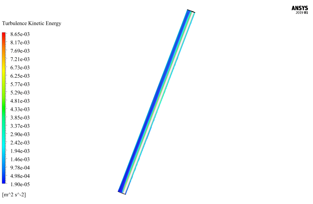
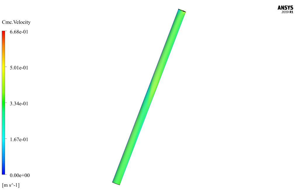
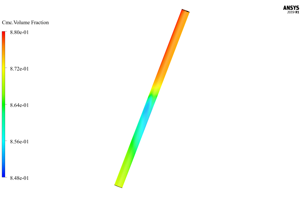
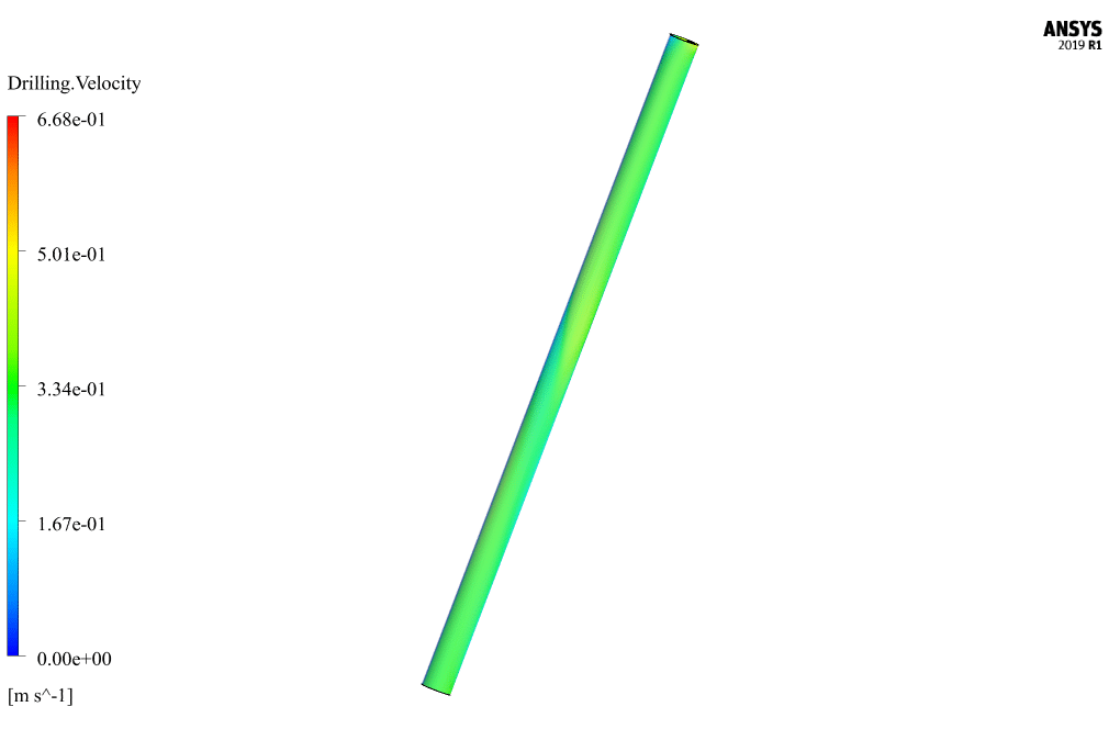
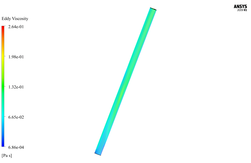
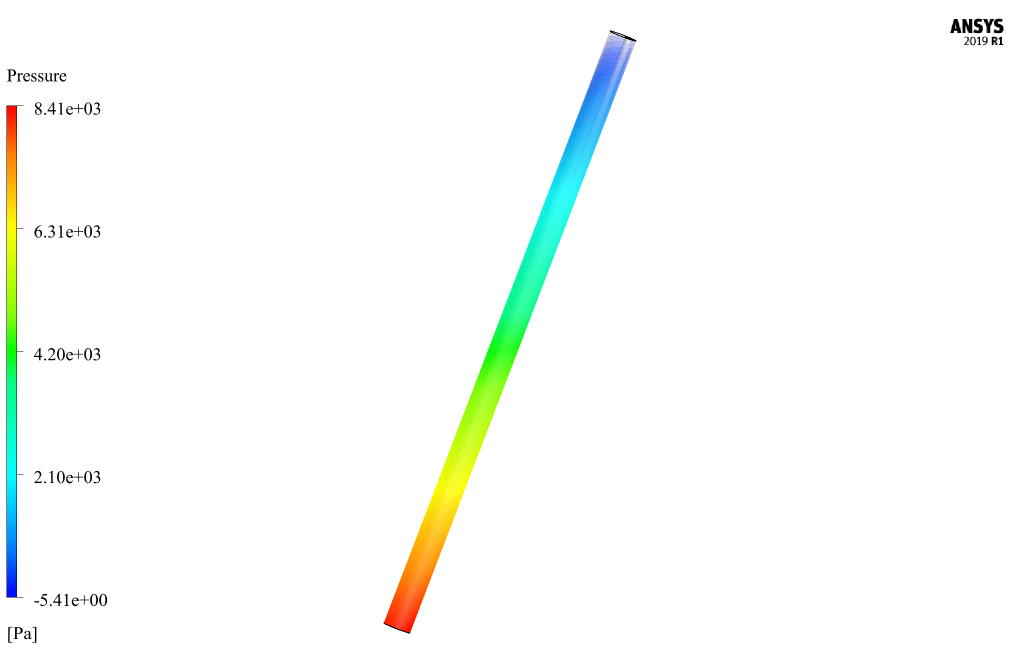
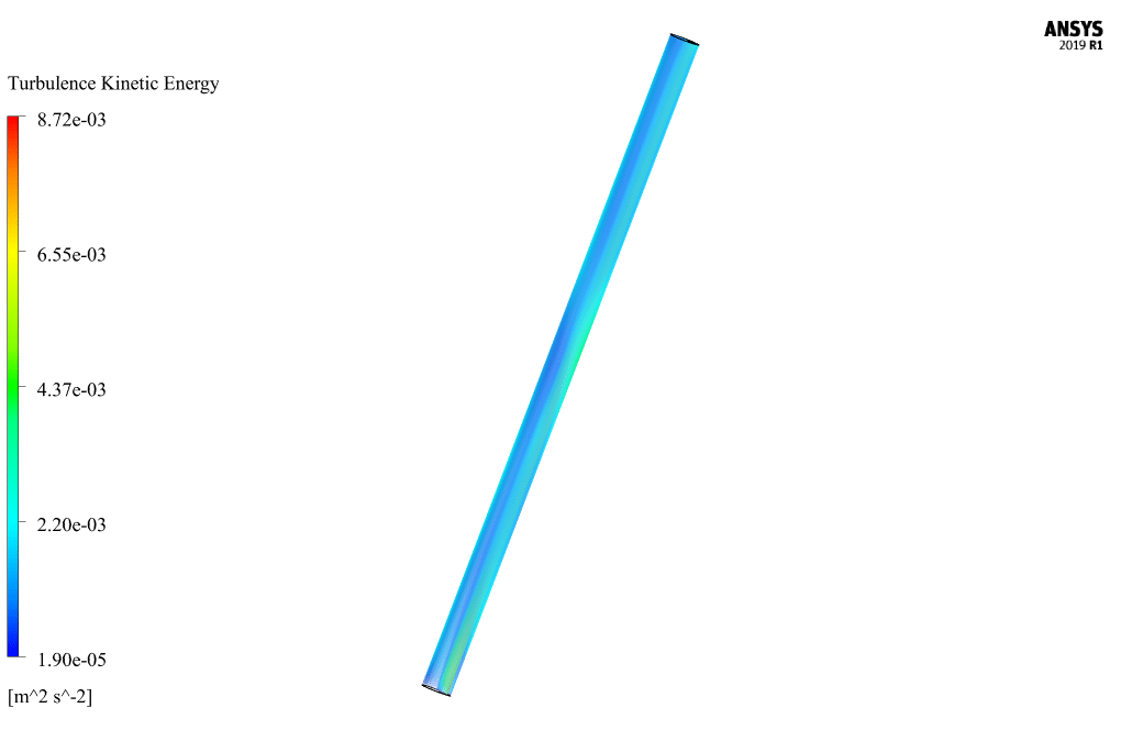
At the end of the solution process, two-dimensional and three-dimensional contours related to pressure, CMC velocity, drilling speed, CMC volume fraction, drilling volume fraction, vortex viscosity, turbulence kinetic energy, and mass flow are obtained.



Monica Bernhard –
Is there a visualization component available with this CFD simulation training for better understanding the fluid behavior and separation process?
MR CFD Support –
Yes, the CFD simulation training for the mud and sand separator in well drilling includes visualizations such as two-dimensional and three-dimensional contours, which illustrate parameters such as pressure, velocity, and volume fraction. These visual aids significantly contribute to the understanding of the fluid behavior and the separation process.
Jack Balistreri –
Can this model correctly capture the behavior of really small particles in the drilling fluid? Or is there any limitation to the size of particles that the simulation can handle?
MR CFD Support –
The Eulerian multiphase model used in this simulation is capable of handling a range of particle sizes, including small particles in the drilling fluid. However, depending on the specific discretization and numerical setup as well as the computational resources available, there may be limitations to the smallest particles that can be captured accurately without significant computational cost. Very small particles might require a finer mesh and more complex models to capture their behavior accurately.
Florida McGlynn –
Does
MR CFD Support –
The sentence seems to be incomplete. Could you please provide more context or clarify your question?
Dr. Armand Klocko II –
I’m impressed with the comprehensive setup in this drilling mud separator simulation. Can you explain the impact of rotational speed increase on mud particle separation? Would we expect more efficiency with faster rotation or is there an optimal speed for best results?
MR CFD Support –
The rotational speed of the cylinder within the mud influences the separator’s efficacy. Increased rotation generally heightens centrifugal forces on the particles, improving separation. However, optimal speed depends on factors like particle size, density, and the fluid’s rheological properties. Efficient separation occurs within a specific speed range, beyond which issues like increased power consumption and potential equipment damage could arise.
Ms. Gwendolyn Ziemann Sr. –
Wonderful concept for mud and sand separation via CFD simulation. The results regarding multi-phase fluid modeling sound promising!
MR CFD Support –
Thank you for your kind review! We are thrilled to hear that our simulation for mud and sand separation in well drilling has met your expectations. It’s encouraging to receive positive feedback about the relevance and application of our CFD models in the industry. If you have any questions or need further assistance, please don’t hesitate to reach out.
Lucius Denesik –
What an informative piece! The comprehensive simulation incorporating non-Newtonian dynamics for the mud separation process appears genuinely representative of real-life drilling scenarios. Impressed by the attempt to accommodate non-linear fluid behavior using the Herschel-Bulkley rule. Great job!
MR CFD Support –
We appreciate your thoughtful compliments! We’re thrilled to know our effort in accurately emulating the non-Newtonian behavior in the drilling simulation resonates with our users. Your feedback is invaluable to us. Thanks for highlighting the intricate details of the implementation!
Kristofer Morissette IV –
I was impressed by the detailed explanation of the multiphase flow model and the non-Newtonian fluids’ behavior in this Well Drilling CFD simulation training. You did an excellent job of describing complex concepts in an accessible way. Thank you for such an informative product.
MR CFD Support –
Thank you for your kind words! We’re thrilled to hear that you found the training informative and accessible. Our goal is to provide clear and detailed explanations to make complex CFD concepts easier to understand. We appreciate your feedback – it encourages us to continue delivering high-quality learning materials. If you have any more questions or need further assistance, don’t hesitate to reach out.
Myron Keeling –
Does the simulation take into account temperature variations or is it isothermal?
MR CFD Support –
The review does not mention any consideration of temperature effects or changes, hence the simulation is assumed to be isothermal. All flow properties and phases appear to be treated at constant temperature, focusing purely on the mechanical aspects of slurry flow and separation.
Martine Tromp –
I’m truly impressed with your simulation of mud and sand separation in well drilling. The intricacies of using an Eulerian multiphase model are apt for depictimg the combination of solid and liquid phases in such an environment. Could you share more about how the usage of a rotating cylinder at 100 rpm manages to achieve the separation of mud particles?
MR CFD Support –
To explain further, the rotating cylinder generates a centrifugal force due to its motion. This force acts perpendicular to the axis of rotation, effectively pushing the heavier mud particles outward towards the cylinder’s outer walls. The separated mud particles can then be raised and removed, while the cleaner non-Newtonian fluid – which encounters less centrifugal force – remains closer to the center. Our simulation represents a common industrial method to segregate component disparities based on density during drilling operations.
Vida Halvorson –
Outstanding content! This simulation demystifies the complex process of well drilling and mud separation. Visualizing the impact of the rotating body inside the drill hole and understanding the unique behavior of Non-Newtonian fluids adds immense value to learning about subsurface engineering actions. Kudos to MR CFD Company for a comprehensive and detailed simulation that’s both informative and technical.
MR CFD Support –
Thank you for your kind words and appreciation! We’re delighted to hear that the simulation met your expectations and provided valuable insights into the well-drilling process and mud separation dynamics. If you have any further questions or need assistance with other simulations, please feel free to reach out.
Dr. Mervin Wunsch –
Thank you for such a thorough course on mud and sand separation in well drilling using ANSYS Fluent. The CFD simulation’s application of the non-Newtonian fluid behavior along with the multiphase model was incredibly insightful. It was particularly interesting to see how the rotating cylinder’s movements facilitated the separation process.
MR CFD Support –
Thank you for your positive feedback. We are thrilled to hear that you found the course insightful and that you appreciated the detailed exploration of non-Newtonian fluid dynamics and the multiphase model in relation to the drilling process. Understanding the interaction between the rotating cylinder and the separation of mud particles is indeed a significant aspect of this simulation that we aimed to demonstrate clearly. It’s great to know that this has enhanced your knowledge. Thank you for choosing our training course!
Ms. Lori Abshire MD –
This training material seems detailed. Could you tell me if a beginner with basic knowledge of fluid dynamics and some ANSYS experience could follow along with this training?
MR CFD Support –
Absolutely, this training is designed to accommodate users with an understanding of fluid dynamics principles and fundamental exposure to ANSYS software. Additional resources and guidance are provided within the materials to support learners through complex concepts and simulation steps.
Joyce Orn –
I’ve read that the primary phase fluid CMC is non-Newtonian. Could you please explain what impact this has on the simulation and results?
MR CFD Support –
Certainly! The non-Newtonian characteristics of the primary phase fluid CMC, governed by the Herschel-Bulkley rule, exhibit a viscosity that is not constant but changes with the shear rate. This behavior influences the flow dynamics, particularly how the fluid strain and stress respond to the rotation of the inner cylinder. Such fluids don’t have a uniform flow profile like Newtonian fluids. In the simulation, these properties require specific numerical handling to accurately describe the flow behavior, resulting in a more complex and realistic depiction of the mud and particle movement within the well drilling environment.
Prof. Eulalia Weber –
I’m fascinated by the use of CMC as the primary non-Newtonian fluid in this simulation. Can you elaborate on how the viscosity of CMC is defined in the simulation, following the Herschel-Bulkley model?
MR CFD Support –
Absolutely! In the simulation, the viscosity of the CMC is described using the Herschel-Bulkley model which is well-suited for shear-thinning non-Newtonian fluids. This model allows for the fluid’s viscosity to be dependent not just on temperature and pressure, but also on the shear rate applied to it. Key parameters for the Herschel-Bulkley model, including the consistency index, flow behavior index, and yield stress, are calibrated based on experimental data of the CMC solution. These parameters together allow for an accurate representation of how the CMC fluid’s viscosity changes in response to mechanical forces during the drilling operation.
Cleta Monahan –
I really enjoyed learning from this CFD simulation training resource. The details on the non-Newtonian fluid characteristics and the multiphase Eulerian model were well-explained, making it easy to understand the complexities involved in mud and sand separation in well drilling.
MR CFD Support –
We’re delighted to hear that you had a beneficial learning experience with our Well Drilling CFD Simulation Training! Understanding the behavior of non-Newtonian fluids in a multiphase context is crucial in simulations like this, and we’re glad the material was clear and informative. Thank you for choosing our product, and we appreciate you taking the time to share your positive feedback!
Santino Medhurst –
I really learned a lot about the simulation of non-Newtonian fluids from this training product. It helped me understand how well drilling and sludge separation processes can be modeled. As someone interested in the oil and gas industry, this gave me insights that I can apply to real-world scenarios. The meshing process and descriptions of fluid behavior were particularly well detailed.
MR CFD Support –
Thank you for your kind words! We are thrilled to hear that our training product on Well Drilling, Mud and Sand Separator simulation could enhance your understanding of non-Newtonian fluids and their application in the oil and gas industry. We strive to deliver detailed and practical knowledge to our customers. Do not hesitate to reach out if you need further assistance or have additional questions related to our simulation trainings.
Madelyn Fadel IV –
The training material sounds complex. Can you explain how the rotating cylindrical body aids in mud separation from the non-Newtonian fluid? Interested in the physics behind that.
MR CFD Support –
In the simulation, the cylindrical body rotates at 100 rpm, creating a centrifugal force. This force helps in separating the heavier mud particles from the non-Newtonian fluid. The rotation induces a radial acceleration, forcing the heavier particles outward against the cylinder wall. The lighter fluid, having less inertia, remains closer to the axis, thereby achieving separation due to differential densities and the effects of the rotational motion.
Sadye Beahan –
The CMC fluid’s viscosity follows the Herschel-Bulkley rule; does the simulation take into account any changes in viscosity as the drilling operation progresses or remains constant throughout the process?
MR CFD Support –
In this simulation, the CMC fluid’s viscosity is indeed governed by the Herschel-Bulkley non-Newtonian model, which allows for changes in viscosity with shear rate. Thus, as the rotational body works within the mixture to separate mud particles from the non-Newtonian fluid, the changes in shear rate will affect the fluid’s viscosity according to this model. This behavior is simulated throughout the drilling operation and is not held constant, providing a more accurate behavior of the non-Newtonian fluid under different shear conditions during the process.
Prof. Hoyt Ullrich DVM –
What is the primary reason for utilizing the Eulerian multiphase model in this simulation?
MR CFD Support –
The Eulerian multiphase model is used in this simulation primarily because it provides a detailed analysis of the intricate interactions between the non-Newtonian fluid and the mud particles in the well drilling process. It is particularly suitable for scenarios where there is a substantial concentration of dispersed particles—in this case, the mud particles—and for capturing the dynamics of systems such as slurry flows and deposition processes where both liquid and solid phases are present.
Sebastian Morissette –
What is the practical application of the findings from this CFD simulation in a real-world drilling operation?
MR CFD Support –
The findings from this CFD simulation can be practically applied in real-world drilling operations to optimize the separation of mud and sand from the drilling fluid, enhance the efficiency of drilling, reduce equipment wear and costs, and minimize environmental impact by improving waste management.
Sandra Runolfsson –
Thank you for the detailed learning resources provided! The simulation of the well drilling and mud separation process has greatly enhanced my understanding of handling non-Newtonian fluids in industrial applications. The step-by-step methodology, from the meshing to the final results, ensured a comprehensive learning experience.
MR CFD Support –
Thank you for your positive feedback! We’re delighted to hear that our simulation resources for well drilling and mud separation helped deepen your knowledge. Your understanding and appreciation for the comprehensive structure of our learning module encourage us to keep providing high-quality training content. If you have any questions or need further assistance in the future, feel free to reach out.
Mark Reinger –
I really enjoyed how the CFD simulation demonstrated the separation process in well drilling. Amazing use of technology!
MR CFD Support –
Thank you for your kind words! We’re delighted to hear that our CFD simulation of the well drilling process met your expectations. Our team takes pride in leveraging advanced technology to demonstrate complex processes effectively. If you have any more feedback or questions in the future, we’d love to hear from you!
Werner Emard II –
I am really impressed with the comprehensive details provided in this Well Drilling, Mud and Sand Separator project using ANSYS Fluent. The use of the Eulerian multiphase model and non-Newtonian fluid simulation for mud separation appear to be well-justified given the complexity of the flow conditions. And the rotational motion implementation for the separation process seems skillfully executed. Terrific job on integrating such an intricate system and explaining it succinctly!
MR CFD Support –
Thank you for your review! We are thrilled to know that you are satisfied with the depth and explanation of the Well Drilling, Mud and Sand Separator project. It’s great to see that you appreciate the careful considerations that went into the Eulerian multiphase model and the implementation of non-Newtonian fluid dynamics. We aim to provide high-quality and well-detailed CFD simulation training materials, and your compliments encourage us to maintain high standards. If you have any further questions or need assistance with your projects, please do not hesitate to reach out to us.
Kyla Fadel –
This CFD simulation involves separating particles using a rotating mechanism, but I’m curious if this model accounts for temperature variations impacting the viscosity of the non-Newtonian fluid or if it is assumed to be isothermal?
MR CFD Support –
In the provided simulation summary, there is no explicit mention of temperature variations affecting the viscosity of the non-Newtonian fluid. The simulation appears to assume an isothermal process, where the viscosity is defined according to the Herschel-Bulkley rule without regard to temperature changes.