 Cfd Simulation Tutorial 1")
Wind Tower (2-D) CFD Simulation Tutorial
Free
- The problem numerically simulates the conjugate heat transfer of airflow in a simplified 4-story wind tower using ANSYS Fluent software.
- We design the 2-D model by the Design Modeler software.
- We Mesh the model by ANSYS Meshing software.
- The mesh type is Structured, and the element number equals 6375.
- The Boussinesq model is used to apply the air density changes due to temperature change.
To Order Your Project or benefit from a CFD consultation, contact our experts via email (info@mr-cfd.com), online support tab, or WhatsApp at +44 7443 197273.
There are some Free Products to check our service quality.
If you want the training video in another language instead of English, ask it via info@mr-cfd.com after you buy the product.
Description
Description
In this project, the conjugate heat transfer (CHT) of airflow in a simplified 4-story wind tower is investigated by ANSYS Fluent software. We perform this CFD project and investigate it by CFD analysis.
The project’s 2D geometry is designed in the Design Modeler, and the computational grid is generated using ANSYS Meshing software. The mesh type is structured, and the element number is 6375.
Wind Tower Methodology
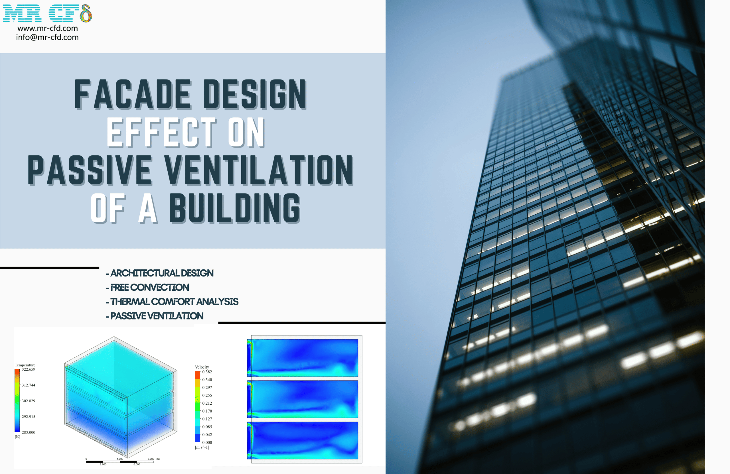
In this problem, conjugate heat transfer (a combination of convective and conductive heat transfer) is modeled inside a wind tower. The diagonal wall on the computational domain’s right side has a temperature of 305K with a heat generation rate of 1000W/m3.
The airflow enters through the inlet boundary on the top left side of the wind tower with a velocity of 12m/s and a temperature of 300K. The air enters each of the 4 levels of the building to ventilate and reduce the temperature.
Also, to simulate natural convection, gravity is enabled in the Y direction, and the Boussinesq model is used to calculate the air density changes due to temperature change (the initial density of air is set to 1.225Kg/m3, and its thermal expansion coefficient is set equal to 0.00331 1/K)
Wind Tower Conclusion
At the end of the solution process, two-dimensional contours related to the velocity, pressure, temperature, streamlines, and velocity vectors inside the computational domain are obtained.
The temperature contour shows the temperature of the heated wall and how the temperature is changed inside the wind tower.
Furthermore, by viewing the contours related to velocity, streamlines, and velocity vectors, one can easily understand that the airflow enters the top levels with more momentum and velocity due to the less hydraulic resistance between the top and bottom levels.
Nevertheless, as seen in the velocity vector contour, the forced airflow entering the bottom levels will cause a rotating airflow inside such levels.
Finally, the air will rise to exit through the pressure outlet boundary on the top right side of the wind tower as it collides with the diagonal hot wall due to the natural convection phenomenon.
Reviews
You must be logged in to post a review.
Related products
-
Sale

Façade Design Effect on Passive Ventilation of Buildings
Original price was: $540.00.$280.00Current price is: $280.00. Internship

Miss Cassidy Schuster –
I followed your wind tower CFD tutorial and the results are impressive! The temperature and airflow patterns were very well illustrated. Thank you for creating such detailed and easy-to-follow content!
MR CFD Support –
We’re thrilled to hear that you found our Wind Tower CFD tutorial valuable and that you’re impressed with the results! It’s always great to see our customers utilize our learning resources to their full potential. Thank you for taking the time to provide such positive feedback. If you have any further questions or need more assistance with your CFD projects, please don’t hesitate to reach out.
Prof. Hank Denesik III –
I’m really impressed with how the temperature and airflow are managed in the wind tower model. Great work with the detailed simulation results!
MR CFD Support –
Thank you for your kind feedback! We’re glad to hear that you found the CFD simulation results for the wind tower insightful and that the information on temperature and airflow management met your expectations.
Kelsie Hintz DVM –
This tutorial seems like a comprehensive source for understanding CHT in wind towers. Could you clarify if the gravity settings specifically affect the convective heat transfer within the simulation?
MR CFD Support –
Absolutely, enabling gravity greatly influences the natural convection process within the wind tower. Since warm air rises and cool air sinks due to density differences, activating gravity and employing the Boussinesq approximation allows the simulation to model the density changes due to temperature variations accurately, which are pivotal for capturing the essence of natural convection in such scenarios.
Dr. Jeromy Emmerich –
I’m deeply impressed with the results of the Wind Tower CFD simulation tutorial. The methodology’s attention to real-world conditions, like incorporating the heat generation rate and using the Boussinesq model for natural convection, highlights the sophistication of this tutorial. Comprehending how the airflow interacts within the wind tower can be quite challenging, but your use of detailed temperature and velocity contours really helped visualize the phenomena. Excellent work providing a clear understanding of conjugate heat transfer within a wind tower’s environment.
MR CFD Support –
Thank you so much for your kind words and for appreciating the in-depth methodological approach of the Wind Tower CFD simulation tutorial. We do our utmost to ensure our tutorials are user-friendly and provide comprehensive insights into the physical phenomena being simulated. We’re thrilled to hear that the tutorial’s level of detail assisted you in visualizing the concepts effectively. If there’s anything more we can do for you or if you ever need further guidance, please do not hesitate to reach out!
Ms. Rosalind Hermann PhD –
The tutorial sounds informative! It’s incredible how you can explore convective flows and heat transfer within the 4-story wind tower. The details about temperature changes and velocity patterns are particularly impressive.
MR CFD Support –
Thank you for your kind words! We’re glad to hear that you found the wind tower CFD simulation tutorial both informative and impressive. Understanding convective flows and heat transfer patterns is crucial for efficient design, and we’re proud that our tutorial could help illustrate these complex phenomena. If you have any more feedback or need further information, please feel free to ask.
Nya Wunsch –
The tutorial seems comprehensive. After following the steps and getting a good grasp of CHT in wind towers, I feel more confident in approaching complex thermal and flow scenarios in my projects!
MR CFD Support –
Thank you for your positive feedback! We’re delighted to hear that our Wind Tower CFD Simulation Tutorial has contributed to your understanding of conjugate heat transfer and airflow dynamics. If you have further questions or need assistance with more advanced applications, feel free to reach out to us.
Dr. Dedric Volkman III –
I’m really impressed with how realistically this simulation mirrored natural convection and airflow within a wind tower! The level of detail shows that quite a bit of thought has gone into accurately capturing the physics of this process which is so critical to passive cooling strategies. Great work!
MR CFD Support –
Thank you for your positive review! We’re delighted to hear that you appreciated the level of detail and realistic simulation of natural convection and airflow in our Wind Tower (2-D) CFD Simulation project. Our team works diligently to ensure our simulations accurately represent the physical phenomena they’re designed to mimic. Your feedback is very motivating for us to continue producing high-quality learning materials.
Vickie Mayert –
I’ve always been intrigued by thermal applications. The tutorial results seem very comprehensive, especially the visible change in airflow dynamics across the different levels. Was the effect of various external temperatures on the wind tower efficiency also analyzed in this tutorial?
MR CFD Support –
In the provided tutorial, the focus is on demonstrating the simulation of airflow and conjugate heat transfer within a specified temperature range of 300K to 305K. External temperature variances and their effects on efficiency were not specifically covered, but this is a great suggestion that could be explored in a more advanced or different tutorial covering environmental conditions on wind tower performance.
Devan Kirlin –
I absolutely enjoyed working with the Wind Tower CFD Simulation Tutorial! It helped me grasp the concept of CHT within a wind tower with such ease.
MR CFD Support –
Thank you for your kind words! We are thrilled to hear that our Wind Tower CFD Simulation Tutorial was effective in conveying the intricate details of conjugate heat transfer in an understandable way.
Prof. Bethel Price PhD –
Your heat transfer CFD tutorial on the wind tower has been incredibly informative, and the results section illustrates the airflow dynamics perfectly. This has given me a clearer understanding of both forced and natural convection in such structures.
MR CFD Support –
Thank you for your positive feedback! We’re glad to hear that the tutorial helped you understand the complex dynamics of heat transfer within the wind tower and that the results section was informative and clear. Your satisfaction with our CFD simulation resources is important to us. If you have any more questions or need further assistance in the future, feel free to reach out!
Eveline Emard –
The tutorial made conduction and convection concepts much clearer, especially how they work together in systems like wind towers. My simulations are now more accurate, thank you!
MR CFD Support –
Thank you for your positive feedback! It’s wonderful to hear that the tutorial was able to enhance your understanding and improve the accuracy of your simulations. If you need any more guidance or have other questions about simulations, feel free to reach out. Happy simulating!
Lamont Gottlieb –
Absolutely remarkable results! I’ve applied the methodologies and findings from this tutorial to an architectural project, and the airflow optimization achieved was noteworthy. The step-by-step aspects of CHT in the dynamics of wind towers were clearly shown, which was very insightful.
MR CFD Support –
Thank you so much for your kind words! We’re thrilled to hear that the CFD simulation tutorial has been applied successfully to your architectural project, leading to impressive airflow optimization. It’s wonderful that the detailed conjugate heat transfer methodology was helpful and clear. We appreciate you sharing your positive experience with our product.
Jaylan Nolan –
I completed the Wind Tower (2-D) CFD Simulation Tutorial and it really clarified the concept of conjugate heat transfer for me. Great use of visuals to show airflow dynamics and temperature changes.
MR CFD Support –
Thank you for your feedback! We’re delighted to hear that our Wind Tower simulation tutorial was effective in enhancing your understanding of conjugate heat transfer. It’s wonderful to know that the visuals helped clarify complex airflow and thermal phenomena.
Prof. Samson Hane Jr. –
The tutorial sounds very informative. I was particularly impressed by how the project captures both forced and natural convection in the wind tower. It’s great to see the velocity vector contour demonstrates the rotating airflow at different levels. I can’t wait to apply these concepts to my own CFD studies for building ventilation.
MR CFD Support –
Thank you so much for your kind words! We really appreciate hearing that our Wind Tower CFD Simulation Tutorial was helpful to you. It’s fantastic to learn that the concepts demonstrated within the tutorial will benefit your own studies. If you ever have any questions or need further assistance as you apply these principles, don’t hesitate to reach out. Best of luck with your CFD journey!
Prof. Dessie Paucek PhD –
I’m delighted by how informative the Wind Tower CFD Simulation Tutorial is. The visualization of termperature and airflow patterns through streamlines and vectors really enhanced my understanding of the concept. This, combined with the structured approach to theory and practical application in ANSYS Fluent, made the learning process very intuitive and rewarding.
MR CFD Support –
Thank you for your positive feedback! We’re thrilled to hear that the tutorial met your expectations and effectively conveyed the complex physics of the wind tower through clear visualizations and explanations. Your satisfaction with the learning process fuels our dedication to providing quality educational material. Do not hesitate to reach out if you need any further assistance or additional resources to enhance your CFD experience.
Julien Terry –
The tutorial sounds very detailed. It’s impressive how it captures both convection and conduction aspects of heat transfer within a wind tower’s confined space. The structured mesh and clear results readers obtained sound very promising for understanding airflow dynamics in building ventilation.
MR CFD Support –
Thank you for your kind words! We’re committed to providing thorough and detailed simulations to ensure a deep understanding of CFD applications. We are glad to hear that our Wind Tower tutorial met your expectations and helped convey the complexities of ventilating air through a building.
Beau Hilpert PhD –
The tutorial was incredibly thorough and practical. The way natural and forced convection were integrated into the simulation helped me understand their contribution to indoor air circulation in a wind tower.
MR CFD Support –
We’re thrilled to know that our Wind Tower CFD Simulation Tutorial was helpful to you in understanding the combined effects of natural and forced convection in air circulation. Your feedback encourages us to keep providing high-quality learning materials. Thank you for taking the time to review our product!
Omari Altenwerth –
I’m highly impressed with this wind tower CFD simulation project. The methodology that considers both convective and conductive heat transfer for realistic physics modeling is exemplary. The thorough investigation into airflow and heat distribution truly demonstrates the powerful capabilities of ANSYS Fluent for such complex simulations.
MR CFD Support –
Thank you for your positive feedback on our Wind Tower CFD Simulation Tutorial. It’s great to hear that the project’s thorough methodology and the accurate physics modeling captured in ANSYS Fluent met your expectations. Your satisfaction is very important to us, and we’re delighted to have provided you with a product that enhances your understanding of fluid dynamics in architectural structures. If you need any further insights or have more interests in CFD applications, please don’t hesitate to explore our other learning materials.
Buster Gerlach I –
I’m truly impressed with the wind tower CFD simulation and the detailed analysis presented. It sounds like a robust tutorial showcasing the effectiveness of proper ventilation and heat transfer models in buildings. Keep up the excellent work!
MR CFD Support –
Thank you for your kind words! We’re glad to hear that you found our Wind Tower CFD simulation tutorial impressive and insightful. It’s great to know that the thoroughness of our analysis and the clear presentation of complex phenomena such as conjugate heat transfer and natural convection met your expectations. We appreciate your feedback and encourage you to stay tuned for more high-quality CFD learning materials.
Oda Powlowski –
I just finished the Wind Tower CFD Simulation Tutorial, and I was impressed by how well the concepts of conjugate heat transfer and ventilation in a multi-story structure were illustrated. The structured approach to the learning materials allowed me to absorb the information effectively and see the practical applications of CFD in building design. Highly recommend for anyone interested in environmental flow within structures!
MR CFD Support –
Thank you for sharing your positive experience with our Wind Tower CFD Simulation Tutorial. It’s fantastic to hear that the tutorial successfully conveyed the concepts of conjugate heat transfer and its significance in architectural CFD analysis. We appreciate your recommendation and are glad you found the learning material informative and structured. If you have any further questions or need assistance with other projects, feel free to reach out.
Santino Boyle II –
I’m really impressed with how the simulation tackles both wind flow and temperature regulation within the wind tower. Great job demonstrating the effectiveness of natural convection in architectural designs!
MR CFD Support –
Thank you for your positive feedback! We are pleased to hear that you found the simulation outcomes illustrative of natural convection processes in wind tower design. Our goal is to provide practical insights through our CFD tutorials, and we appreciate your recognition of our efforts to achieve this.
Felix Turner –
I want to use this tutorial for designing a real wind tower with minor modifications. Does it cover guidelines for assessing the changes needed for real-life buildings, or is it just a theoretical demonstration of airflow in a simplified structure?
MR CFD Support –
The Wind Tower (2-D) CFD Simulation Tutorial is designed as a theoretical guide to demonstrate airflow within a simplified wind tower structure. It utilizes concepts that can be foundational for designing a real wind tower, but applying modifications for real-life structures will need additional considerations based on practical design parameters, environmental conditions, and specific building codes. However, the tutorial provides a strong CFD framework that can be a stepping stone for more complex, real-world applications.
Jan Dooley –
Could you describe how the gravity and Boussinesq model were critical for the natural convection simulation in this wind tower?
MR CFD Support –
Certainly! In the simulation, gravity is a vital factor as it drives natural convection currents within the wind tower. The introduction of gravity in the Y-direction allows the modelling of buoyancy effects, where warmer and thus less dense air rises, while cooler and denser air descends. The Boussinesq approximation accounts for the density changes of the air as a function of temperature, allowing the simulation to capture density variations due to thermal expansion or contraction. These combined effects help accurately model the natural convection processes that are integral to the thermal regulation in the 4-story wind tower simulation.
Mrs. Marta Gutkowski –
The tutorial for the Wind Tower CFD Simulation was incredibly helpful. It gave me a clear understanding of the setup and analysis of natural convection in a building structure. The details on the boundary conditions and results provided insightful data analysis.
MR CFD Support –
Thank you for your positive feedback on the Wind Tower CFD Simulation tutorial. We’re delighted to hear that it enhanced your understanding of natural convection and the analysis of CFD in building structures. If you have further queries or need more assistance, feel free to reach out. Thank you for choosing our tutorials to advance your skills.