
Turbo Ventilator, ANSYS Fluent CFD Simulation Tutorial
$140.00 Internship
- The present CFD project simulates an Air Turbo Ventilator via ANSYS Fluent software.
- We designed the geometry using ANSYS Design modeler software and created the mesh using ANSYS meshing software.
- The total number of elements is 2094625.
- The Frame Motion (MRF) method has been used in Cell Zone Conditions to define rotation.
To Order Your Project or benefit from a CFD consultation, contact our experts via email (info@mr-cfd.com), online support tab, or WhatsApp at +44 7443 197273.
There are some Free Products to check our service quality.
If you want the training video in another language instead of English, ask it via info@mr-cfd.com after you buy the product.
Description
Introduction
This project is related to a simulation of an Air Turbo Ventilator using ANSYS Fluent software. We perform this CFD project and investigate it by CFD analysis.
This system is included in the category of passive ventilation methods. In passive ventilation systems, no active mechanical device is involved.
Generally, passive ventilation systems are included in two groups, which are wind-driven and buoyancy-driven.
The air turbo ventilator is one type of wind-driven passive ventilation group. This means that only the pressure difference causes air circulation.
A turbo air ventilator uses air energy to move out the airflow. An air turbo ventilator consists of a rotating turbine installed on the roof of buildings.
The warm air is light and less dense and goes to the top of the space. The contact of the air with the ventilator blades causes a rotational movement. On the other hand, the free wind flow on the buildings’ roofs strengthens the blades’ rotation speed.
So, the pressure difference between the inside and outside of the building is created, and the ventilator causes air suction.
This system has many advantages. They can work continuously 24 hours a day while consuming no energy. In addition, these systems can air conditioning by removing dust and pollutants.
We designed the geometry of the model using Design Modeler software. The computational zone of the model is related to the room’s interior space. Two air turbo ventilators are installed on the ceiling of this room.
Then we meshed the model using ANSYS Meshing software. The meshing is unstructured, and the number of created cells equals 2094625.
Turbo Ventilator Methodology
Using ANSYS Fluent software, we numerically simulated this model according to computational fluid dynamics (CFD). This problem is independent of time and steady state, and the solution is based on the pressure-based solver.
As we said, natural convection heat transfer also happens in this problem. Natural convection is created based on the buoyancy effect. This means that changes in temperature cause changes in density. Warm air is lighter and less dense and rises upwards.
Therefore, the current system is useful for the exit of hot air. The entry of cool air from the floor of the room and the air suction from the exit panel of the tower helps the exit of hot air.
In this problem, we must define the rotation movement of two ventilators. We use the multiple reference frame (MRF) methods.
We create two distinct zones adjacent to the turbine blades within the total computational domain. Now we define the rotational movement for these zones.
Since the airflow direction is parallel to the central axis of the ventilators, we use the frame motion method. We have set the rotational velocity equal to 100 rad/s.
Turbo Ventilator Conclusion
After the simulation, we obtained 2D and 3D pressure and velocity contours. We also obtained 2D and 3D velocity vectors.
The pressure contour correctly shows the pressure difference. So the pressure difference causes air suction.
On the other hand, the velocity vectors around the ventilator blades show the rotational movement of the airflow. These velocity vectors in the vicinity of the ventilators show that air suction from inside the room occurs through the ventilators.
So, we conclude that this air turbo ventilator system performs the air conditioning process correctly.
Reviews
You must be logged in to post a review.
Related products
-
Sale

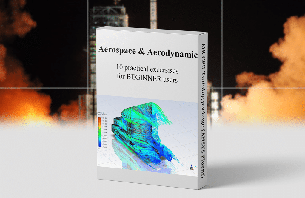
Aerodynamic and Aerospace Training Package for Beginners, 10 Learning Products
Original price was: $840.00.$299.00Current price is: $299.00. Internship

Pedro Hill –
Terrific tutorial on the air turbo ventilator simulation! The step-by-step walkthrough clarified the concepts, especially the way natural convection was incorporated using buoyancy effect and how the multiple reference frame method was used to simulate the rotating turbine. The use of clear visuals in illustrating the velocity vectors and pressure contours really helped cement my understanding.
MR CFD Support –
Thank you for your positive feedback! We’re thrilled to hear that our tutorial on the air turbo ventilator simulation was helpful and the visuals aided in your comprehension. If you have any further questions or need assistance on another topic, feel free to reach out!
Louvenia Prohaska –
I’m blown away by how the air turbo ventilator works without energy and yet manages to achieve efficient air circulation. Great work on demonstrating this with CFD analysis!
MR CFD Support –
Thank you for your kind words! It’s impressive how passive ventilation systems like the air turbo ventilator can provide cost-effective and energy-efficient solutions. We’re glad that our CFD analysis could clearly demonstrate this process to you.
Otto Yundt Sr. –
I’m really impressed by the detailed explanation of air flow mechanisms in the Turbo Ventilator simulation. The usage of the multi-frame reference and depiction of pressure and velocity vectors provided a comprehensive understanding of the system!
MR CFD Support –
Thank you for your positive feedback! We’re glad that the detailed explanations and simulation techniques helped in enhancing your understanding of the air turbo ventilator system. We always strive to provide comprehensive tutorials for an informative and enriching learning experience.
Mariela Smith –
I am incredibly impressed with the detailed analysis provided by the MR CFD Company in their Turbo Ventilator CFD Simulation Tutorial. It clearly shows how passive ventilation systems can be effectively modeled and analyzed using ANSYS Fluent. The explanation of the methodology, especially the implementation of the MRF method for the rotating turbines, was very well presented.
MR CFD Support –
Thank you so much for your kind words and for recognizing the depth of our CFD analysis. We’re delighted to hear that our tutorial on the Turbo Ventilator using ANSYS Fluent met your expectations and provided you with a clear understanding of passive ventilation system simulations. Your acknowledgment of the effort we put into explaining the methodology is greatly appreciated. If you ever have more inquiries or need further assistance, please don’t hesitate to reach out!
Jaclyn Crooks –
The project on the Air Turbo Ventilator was excellently laid out. The explanation of how the passive ventilation system works, especially focusing on natural convection, was clear and understandable. I appreciate the detail on how you used the multiple reference frame methods for the ventilator blades. It was fascinating to learn about the implementation of rotation and to visualize the air movement through the 2D and 3D contours!
MR CFD Support –
Thank you for your positive feedback on the Air Turbo Ventilator CFD Simulation Tutorial. I’m delighted that you found the project well-explained and educational, especially regarding the passive ventilation systems and the use of the multiple reference frame method. Visualizations are indeed crucial in understanding fluid dynamics, and it’s great to know our efforts to present these insights were appreciated. Thank you for choosing our learning products!
Jillian Gottlieb V –
This Air Turbo Ventilator simulation sounds intriguing! Can it be used to model different climatic conditions or to simulate variations in external wind speed to see how it affects the efficiency of the air suction and overall air conditioning process?
MR CFD Support –
The Air Turbo Ventilator simulation performed using ANSYS Fluent is quite versatile and can indeed be adapted to model various climatic conditions and external wind speeds. By altering the boundary conditions to replicate different temperature profiles, wind speeds, and directions, we can evaluate the device’s performance under varying conditions. Therefore, the effectiveness of air suction and ventilation efficiency can be thoroughly assessed using CFD analysis for optimization in different environments.