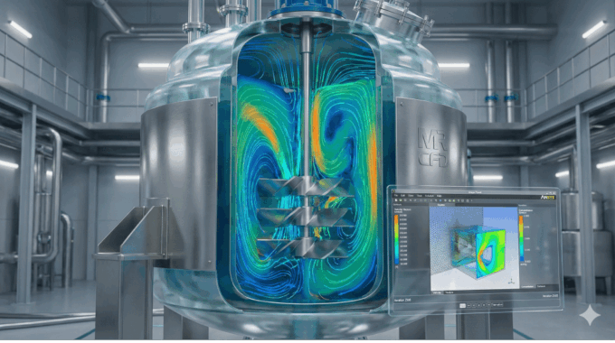
CFD Analysis for Chemical Reactors: Improving Mixing and Yield
In today’s chemical industry, every percentage improvement in reactor performance translates directly into profit and competitive advantage. Computational Fluid Dynamics (CFD) has become the engineer’s precision lens for understanding, optimizing, and innovating chemical processes that once relied on trial and error. From pharmaceuticals to petrochemicals, simulation empowers teams to improve mixing, yield, and safety while cutting experimental cost and time.
At MR CFD, our consultants have spent more than two decades refining advanced CFD for chemical engineering workflows. We bring aerospace‑level simulation rigor to processing plants—validating reactor designs, uncovering hidden inefficiencies, and delivering measurable return on investment (ROI). In this article, we’ll explore how CFD reshapes chemical reactor design, explain the underlying modeling fundamentals, discuss applications across reactor types, and show you exactly how MR CFD transforms simulations into business value.
Why Is CFD Crucial for Chemical Engineering Today?
Modern process industries face constant pressure to increase production agility, improve quality consistency, and adhere to stricter sustainability metrics. Traditional design methods—based largely on empirical correlations or pilot‑scale tests—are increasingly unable to meet this pace. CFD simulation for chemical reactors offers a virtual laboratory where every design variation can be tested under true operating conditions before the plant steel is cut.
How do conventional reactor design approaches fall short?
Conventional chemical reactor design relies heavily on averaged parameters such as global mixing coefficients or bulk temperature estimates. These overlook the microscopic interplay of turbulence, multiphase interactions, and chemical reactions inside the reactor.
Common limitations include:
- Scale‑up uncertainty: Laboratory data often fails to scale linearly, leading to performance losses up to 30 % at full scale.
- Incomplete mixing characterization: Empirical tests cannot visualize segregated zones or dead volumes that lower product uniformity.
- Energy inefficiency: Over‑aggressive agitation or heat flux safety margins raise operating costs.
- Limited scenario testing: Experimental setups rarely explore dozens of “what‑if” conditions due to cost and time.
Without predictive modeling, engineers must build expensive pilot plants hoping they behave as expected. CFD replaces this uncertainty with physics‑based prediction of every velocity field, concentration gradient, and thermal layer—long before production begins.
What measurable benefits does CFD bring to chemical engineers?
The tangible outcomes of CFD span productivity, sustainability, and profitability. Across our MR CFD projects, we routinely observe:
| Improvement Area | Typical CFD‑Enabled Gain | Business Impact |
|---|---|---|
| Mixing uniformity | +20 – 40 % | Better product quality & reduced rework |
| Reaction yield | +5 – 15 % | Higher throughput without new reactors |
| Energy efficiency | +10 – 25 % | Lower power + cooling costs |
| Design cycle time | –30 – 50 % | Faster R&D and market launch |
| Scale‑up reliability | ↑ Repeatability | Fewer physical prototypes |
When those numbers are converted into production terms—tons of product per day, kilowatts saved per batch, or maintenance hours avoided—the ROI is immediate. CFD’s real power lies not only in simulation accuracy, but in business decision enablement: choosing the best design early and confidently investing capital.
Next, let’s examine how CFD actually captures the coupled physics inside complex chemical reactors.
How Does CFD Modeling Work in Chemical Reactors?

At its core, CFD solves the Navier‑Stokes equations for fluid motion while coupling them with scalar transport of species, energy, and sometimes electric or granular effects. A well‑configured simulation converts geometry, boundary conditions, and reaction kinetics into a quantitative picture of flow, heat, and mass transfer—key drivers of reactor efficiency.
What are the main CFD models used in reactor analysis?
Different modeling frameworks target specific physical regimes:
- Turbulence Models
- RANS (Reynolds‑Averaged Navier‑Stokes): Efficient for steady‑state mixing analysis and quick design screening.
- LES (Large Eddy Simulation): Resolves transient vortex dynamics critical for predicting local mixing and instantaneous concentration fluctuations.
- DES/Hybrid: Balances accuracy and computational cost for large reactors.
- Multiphase Models
- Volume of Fluid (VOF): Ideal for immiscible liquid systems or gas–liquid surface tracking.
- Eulerian–Eulerian: Handles dense gas‑liquid or solid‑gas suspensions such as fluidized beds.
- Discrete Phase Model (DPM): Traces individual droplets or catalyst particles within a continuous fluid.
- Species Transport and Reaction Models
Used to simulate mixing‑limited or kinetically limited reactions, enabling direct prediction of yield versus mixing rate.
At MR CFD, we often integrate Ansys Fluent chemical reaction modeling frameworks with custom sub‑routines (UDFs) to represent proprietary kinetics or catalyst surface reactions accurately.
How do reaction kinetics integrate into CFD simulations?
Chemical reactions can be homogeneous (occurring within one phase) or heterogeneous (surface or multiphase). CFD connects reaction kinetics to local flow parameters:
- Local residence time (τ): Determines how long reactants stay in reactive zones.
- Temperature & concentration fields: Drive reaction rate via Arrhenius expressions.
- Catalyst surface area exposure: For solid‑supported reactions, CFD maps diffusion limitation layers.
An example: In an exothermic liquid‑phase synthesis reactor, coupling the energy equation with detailed stoichiometric kinetics reveals hotspot formation and guides cooling jacket redesign. We validated such models at MR CFD against experimental calorimetry data, achieving < 5 % deviation—proving CFD’s reliability for process control design.
How can CFD predict heat and mass transfer limitations?
Heat and mass transfer bottlenecks often dictate reaction selectivity. CFD locates these limitations by computing:
- Nusselt and Sherwood distributions around impellers or catalyst pellets.
- Temperature variance maps indicating under‑cooled regions.
- Diffusion path lengths showing where reactant transport restricts conversion.
The ability to visualize these characteristics makes corrective action straightforward—alter impeller blade curvature, introduce internal baffles, or modify feed orientation. These insights would be nearly impossible through experimental observation alone.
Smoothly connecting to application diversity, let’s explore how different reactor configurations benefit distinctively from these capabilities.
Which Chemical Reactor Types Benefit Most from CFD?

Every reactor type—whether stirred, tubular, or fluidized—presents its own scaling challenges. CFD provides tailored diagnostic and optimization tools for each geometry, making it indispensable throughout process industries.
How does CFD enhance Stirred Tank Reactor (STR) performance?
Stirred Tank Reactors (STRs) remain the backbone of chemical and biochemical processing due to their flexibility. Yet subtle geometry changes can shift mixing dynamics dramatically.
Typical optimization tasks include:
- Impeller selection & spacing: CFD compares axial‑flow vs. radial‑flow impellers, balancing power draw and shear rate to achieve target mixing times.
- Baffle configuration: Simulations reveal dead zones behind inadequate baffles or vortex formation when baffles are too small.
- Gas–liquid dispersion: Multiphase CFD quantifies bubble residence time and interfacial area for better mass transfer.
In a pharmaceutical crystallization project handled by MR CFD, implementing CFD‑based impeller redesign reduced batch mixing time by 38 % and improved particle size uniformity—directly enhancing downstream filtration efficiency.
Importantly, CFD allows virtual DOE (Design of Experiments) across dozens of setups without wasting a single milliliter of reactant. For R&D teams, this equates to hundreds of thousands of dollars saved annually.
Why is CFD critical for Plug Flow Reactors (PFRs) and Tubular Reactors?
While plug‑flow theory assumes perfect axial mixing and zero back‑mixing, real industrial reactors deviate substantially. CFD analysis for process intensification replaces these assumptions with detailed field data:
- Residence time distribution (RTD): By simulating tracer concentration, engineers can quantify dispersion coefficients and identify channeling.
- Wall heat‑loss effects: Temperature gradients across tube walls directly impact selectivity and yield.
- Catalyst packing heterogeneity: CFD can simulate local porosity variation affecting pressure drop and conversion.
We applied this approach for a petrochemical dehydrogenation unit where CFD predicted a 7 % temperature non‑uniformity causing yield reduction. Adjusting heating‑zone profiles based on model output restored uniform conversion and increased annual output by 9 %.
The insight extends further to reactor scaling—predicting exactly how tube diameter affects axial dispersion and heat‑transfer performance—without executing costly pilot runs.
How is CFD applied to Fluidized Bed and Multiphase Reactors?
Fluidized beds epitomize multiphase complexity: solid particles interact with upward gas streams, exhibiting bubbling, slugging, or turbulent regimes. Modeling them once required massive experiments; now, multiphase flow simulation in reactors performed via Eulerian–Eulerian or hybrid DEM–CFD techniques captures these interactions in detail.
Key outputs include:
- Particle velocity fields and bed expansion.
- Cluster formation and defluidization detection.
- Temperature and concentration homogeneity through the bed height.
For example, in an MR CFD energy‑sector project, simulating a catalytic cracking fluidized bed revealed inefficient distributor plates that created coarse particle bypassing. CFD‑driven redesign raised gas–solid contact efficiency by 22 %, reducing regeneration energy consumption by 15 %.
Such results illustrate how multiphase CFD advances both process sustainability and equipment reliability by clarifying otherwise invisible fluid‑solid behaviors.
How Does MR CFD Deliver Accurate and Validated Reactor Simulations?

The hallmark of professional CFD consulting is repeatability, not artistic visualization. At MR CFD, every simulation we deliver undergoes a rigorous validation and verification pipeline designed around industrial CFD best practice. With more than 2 000 + simulation projects across aerospace, energy, and chemical sectors, we’ve refined methods that consistently transform simulation insight into actionable design change.
What best practices ensure reliable CFD results?
High‑fidelity CFD is only as sound as its numerical framework. MR CFD consultants adhere to proven principles that meet peer‑reviewed criteria:
- Grid Independence & Benchmark Studies 🧩 – We perform mesh‑refinement analysis until solution metrics (pressure drop, mixing index, heat‑transfer coefficient) vary less than 2 %. This ensures accuracy regardless of grid density.
- Validation Against Experimental Data 🎯 – Whenever possible, predicted data are compared with laboratory or plant measurements. In one polymerization reactor case, predicted temperature rise (ΔT) matched thermocouple readings within ± 3 °C.
- Model Calibration & Uncertainty Quantification – Kinetic parameters and turbulence constants are tuned based on reference datasets to minimize systemic bias.
- Time‑Step & Convergence Controls – Adaptive under‐relaxation and residual monitoring avoid false convergence, guaranteeing physically sound outcomes.
Such discipline enables MR CFD to produce verified simulation accuracy that withstands technical audits and regulatory submissions.
How does MR CFD’s workflow accelerate simulation projects?
Speed without sacrificing accuracy defines our HPC‑assisted CFD workflow. Using dedicated high‑performance computing clusters, geometry pre‑processing, meshing, and solution steps become massively parallelized.
Typical workflow:
- Scoping & Physics Definition – Joint workshops with client engineers clarify objectives, cost targets, and measurable KPIs.
- Geometry + Mesh Automation – Custom scripting (Fluent TUI + Python) creates consistent meshing templates for rapid variant testing.
- Solver Execution on HPC Nodes – Runs distributed over 128 – 512 cores, reducing wall time by 70 %.
- Post‑Processing via AI‑aided Tools – Automated extraction of contour and streamline metrics for immediate interpretation.
- Reporting & Design Review – Engineering report with economic interpretation (energy per batch, throughput increase, ROI).
The outcome: projects that once required six weeks of iteration can now deliver validated conclusions in under 10 days—empowering design decisions while competitors are still configuring their first model.
How does MR CFD ensure ROI‑focused project delivery?
Every MR CFD engagement begins and ends with quantitative business metrics. Instead of reporting only flow contours, we deliver tangible outcomes:
- Energy & Yield Savings Reports → translating flow uniformity into actual kilowatt or yield gains.
- Process Upgrade Roadmaps → showing capital retrofits justified by simulation payback period (< 12 months typical).
- Executive Summaries for Stakeholders → bridging the technical and managerial worlds to secure funding.
One client from the specialty‑chemical sector saw a $280 000 per year saving after implementing CFD‑recommended impeller modifications. That’s why we emphasize ROI with every result—not only scientific precision.
Having examined MR CFD’s methodology, let’s explore tangible case stories where CFD translated into operational excellence.
What Are Real Industrial Examples of CFD Success in Reactors?
Experience across industries confirms that simulation isn’t theoretical—it’s transformational. Below are condensed yet representative examples derived from MR CFD’s extensive portfolio (shared with client permission or anonymized).
How was CFD used to increase mixing efficiency in a pharmaceutical reactor?
In pharmaceutical production, batch reproducibility determines patient safety and regulatory compliance. A global pharma client experienced inconsistent API crystal size due to non‑uniform mixing in a 10 m³ jacketed STR.
CFD Approach :
- Modeled multiphase flow (liquid + solid suspension) using RANS k‑ω SST turbulence model.
- Evaluated impeller options under varying agitation speeds.
- Incorporated real rheological data from lab measurements.
Outcome :
CFD identified stagnation zones behind baffles occupying 8 % of tank volume. After geometric revision and slight impeller speed reduction (‑12 %), overall mixing time dropped 37 %, while power consumption fell 18 %. The plant avoided hardware replacement—ROI < 6 months.
How did CFD optimization improve yield in a petrochemical process?
A petrochemical facility utilizing tubular catalytic reactors faced uneven conversion and excessive by‑product formation. MR CFD built a coupled flow‑reaction model embedding first‑order dehydrogenation kinetics.
Findings revealed thermal gradients exceeding 25 °C near wall regions due to uneven coil heating. Through simulated redesign of coil layouts and improved insulation zones, temperature variation shrank to < 5 °C and yield increased 10 %. Net benefit: + $ 1.3 million/year of product output without additional capital equipment.
What insights did CFD provide that experiments could not?
Unlike experiments limited to point‑wise measurements, CFD visualizes entire fields of velocity, pressure, and species distribution. It unveils hidden loss mechanisms such as:
- Recirculation pockets that trap reactants leading to incomplete conversion.
- Short‑circuit streams causing bypass and low residence time.
- Localized overheating responsible for catalyst sintering or polymer degradation.
These visual diagnostics enable design teams to innovate confidently—rethinking reactor internals, feed nozzles, or cooling strategies without guesswork.
By documenting these learnings, MR CFD builds institutional knowledge across client organizations, turning each project into a reference benchmark.
Now that we’ve seen proven success stories, let’s clarify how any engineering team can begin cooperating with MR CFD to realize similar gains.
How Can Engineers and Teams Start Using CFD with MR CFD?
Whether you’re designing a new pilot plant or troubleshooting an under‑performing reactor, integrating CFD with expert guidance accelerates understanding and solution delivery.
What is MR CFD’s process for reactor simulation projects?
Our client journey is structured for transparency and speed:
- Initial Consultation (Free 30‑min Session) – Discuss objectives, constraints, and available data with a senior consultant.
- Proposal & Scope Definition – MR CFD outlines recommended physics models, timelines, and deliverables tied to ROI metrics.
- Data Collection & Model Setup – Geometry acquisition, boundary condition review, and experimental data gathering if available.
- Simulation & Validation Phase – Continuous progress updates; clients can view intermediate results via secure dashboard.
- Results Delivery & Knowledge Transfer – Final report, review meeting, and optional technology handover including simulation templates.
Each stage blends client insight with MR CFD expertise, ensuring both technical validity and organizational alignment.
How can MR CFD training and courses accelerate team capability?
In addition to consulting, we empower in‑house engineers through tailored education. Our Ansys Fluent Course and extended CFD courses for process engineers cover:
- Multiphase and reactive‑flow modeling fundamentals.
- Best practices for grid independence studies and solver optimization.
- Hands‑on workshops using actual industrial reactor cases.
Participants learn how to interpret CFD results for managerial decisions—turning raw simulations into strategic advantage. Teams often begin with consulting, then transition into skill‑development programs to internalize CFD culture.
How do I request a free consultation or case evaluation?
Getting started is straightforward: visit MR CFD’s contact portal or email info@mrcfd.com with a brief outline of your challenge—geometry details, operating conditions, and current issues. Within 48 hours you’ll receive a scoping response from a certified Ansys expert recommending the best path forward.
Empowered by CFD insights, engineers evolve from data gatherers to design decision‑makers—closing the loop between computation and production.
Frequently Asked Questions
What software tools does MR CFD use for chemical reactor simulations?
We primarily employ Ansys Fluent, augmented by proprietary automation scripts and visualization APIs. In complex multiphase or granular applications, we integrate CFX, OpenFOAM, or DEM coupling platforms. Choosing the right solver depends on flow regime, chemical reactions, and available hardware resources.
How long does a typical CFD simulation of a chemical reactor take?
Computation time varies by reactor size, physics, and mesh density. With MR CFD’s HPC platform (128 – 512 cores), a steady‑state STR case may converge within 8–12 hours, whereas transient LES multiphase runs could take several days. We always balance turnaround speed and accuracy through adaptive meshing and parallel scaling.
What input data are needed to start a reactor CFD study?
Essential inputs include reactor geometry (CAD or drawings), operating conditions (flowrates, temperature, pressure, viscosity), and—if applicable—chemical kinetics or heat‑generation data. Supplementary experimental or P&ID information further improves validation fidelity.
Can CFD replace experimental lab tests for reactor design?
CFD cannot fully replace experiments but greatly minimizes their number. It guides which parameters truly matter, ensuring experiments are focused and confirmatory instead of exploratory. Typically, CFD trims physical testing by 40–60 % while offering deeper variable insights.
How do CFD predictions compare with plant‑scale performance?
When validated with representative data and benchmark results, deviation is often < 5 %. Any mismatch usually arises from unmeasured boundary conditions. MR CFD’s practice of iterative calibration ensures consistent alignment between digital and real performance.
What is the ROI of CFD consulting for chemical process companies?
Return varies by scale but averages 3‑to‑10× investment within the first operational year. Savings stem from higher yield, reduced energy input, fewer failed prototypes, and improved reliability—clear evidence that simulation is a profit center, not a cost.
How do MR CFD’s courses help engineers learn Ansys Fluent faster?
Our courses follow a project‑based curriculum. Instead of generic tutorials, participants analyze industrial geometry, interpret contour results, and adjust real solver settings under expert supervision. Knowledge retention exceeds typical self‑learning because it’s tied to tangible outcomes.
Can MR CFD help optimize both single‑phase and multiphase reactors?
Absolutely. Our portfolio spans single‑phase liquid mixers, gas–liquid bubble columns, solid–gas fluidized beds, and reactive multiphase risers. Each regime requires different modeling frameworks, and MR CFD provides in‑house specialists for every domain.
How can CFD support scale‑up from laboratory to production reactors?
CFD quantifies performance metrics—mixing time, shear, RTD—independent of reactor scale, allowing direct extrapolation. By matching dimensionless numbers (Re, Fr, Da), engineers can predict full‑scale behavior with confidence, minimizing pilot trials.
Is CFD applicable to green chemistry or renewable energy processes?
Yes 🌱. CFD drives scale‑up of biodiesel transesterification, electrolyzers for hydrogen production, and CO₂‑capture units. Simulation optimizes mass transfer and energy efficiency, aligning perfectly with sustainable‑process goals.
Conclusion – Turning Simulation Insight into Industrial Advantage
The chemical industry’s competitiveness increasingly depends on how well organizations convert fluid‑dynamic understanding into operational gains. CFD for chemical engineering is no longer an optional R&D tool—it is the foundation for efficient design, safe operation, and sustainable growth. Through rigorous validation, advanced HPC infrastructure, and ROI‑oriented delivery, MR CFD has proven that simulation can cut pilot costs by half while boosting yields and energy efficiency across numerous reactor types.
Looking forward, integration of AI‑driven design optimization, digital twins, and real‑time CFD analytics will make virtual reactors indispensable to every process engineer’s workflow. Whether you aim to redesign impellers, evaluate catalyst placement, or train your team in Ansys Fluent, MR CFD stands ready to partner with you on that transformation.
📞 Start your reactor optimization journey today—request a free consultation and discover how your plant can achieve better mixing, higher yield, and measurable ROI 🚀.
Related Posts
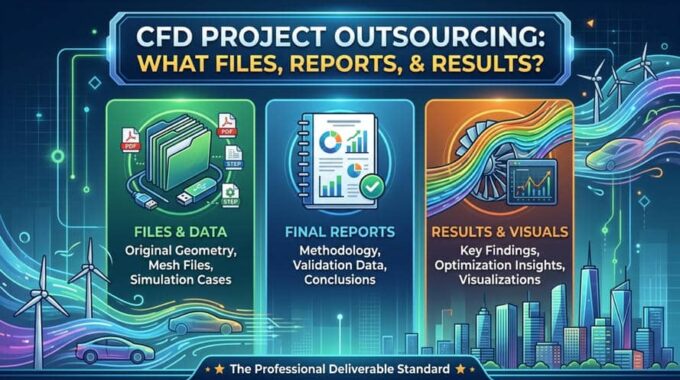
CFD Project Outsourcing: What Files, Reports, and Results Should You Expect?
When engineering teams decide to outsource CFD simulation, the conversation almost always starts with capability and…
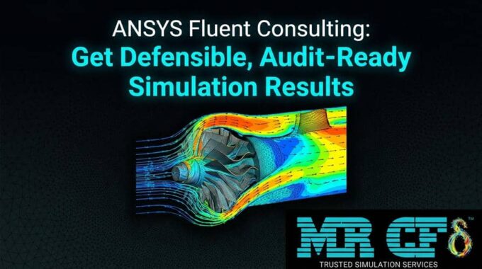
ANSYS Fluent Consulting: Get Defensible, Audit-Ready Simulation Results
You need ANSYS Fluent results that can survive scrutiny — a design review, a client…
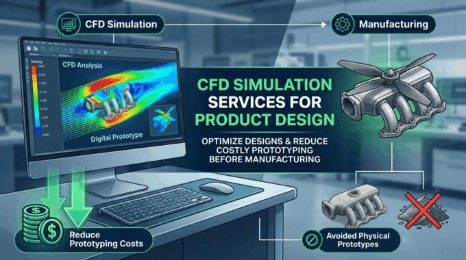
CFD Simulation Services for Product Design: Reduce Prototyping Cost Before Manufacturing
In modern product development, the most expensive mistakes are often discovered after money has already…
Comments (0)