How Can Advanced CFD for Water Treatment Optimize Plant Efficiency and Cut Costs?
In the high-stakes world of municipal and industrial water treatment, efficiency is rarely a visual problem—it is a hydrodynamic one. For decades, engineers relied on empirical formulas, “rule of thumb” safety margins, and expensive physical prototyping to design tanks and reactors. The result? Facilities that function, but often at the cost of massive chemical overuse, high energy consumption, and frequent compliance headaches.
Today, the paradigm has shifted. CFD for water treatment (Computational Fluid Dynamics) allows us to peer inside the “black box” of concrete clarifiers and contact tanks. It transforms invisible flow patterns into actionable data, allowing plant operators to virtually test design changes before pouring a single cubic meter of concrete.
As a Senior Consultant at MR CFD, I have witnessed firsthand how a validated simulation can turn a struggling facility into a model of efficiency. Whether you are retrofitting a 50-year-old clarifier or designing a state-of-the-art membrane bioreactor, the physics of fluid flow dictates your operational expenditure (OPEX). This article explores how advanced simulation strategies, from Residence Time Distribution (RTD) analysis to multiphase modeling, are redefining industry standards.
What are the Critical Challenges in Modern Water Treatment that CFD Solves?
The water industry is currently facing a “perfect storm” of challenges: aging infrastructure, tightening environmental regulations (such as stricter disinfection by-product limits), and skyrocketing energy costs. In this environment, the legacy “design by spreadsheet” approach is no longer sufficient.
The core issue lies in the scale and opacity of the process. In a 5-million-gallon tank, it is physically impossible to see if the water is mixing uniformly or if sludge is settling correctly simply by looking at the surface.
Here are the specific pain points where CFD simulation of wastewater treatment plants proves indispensable:
- Hydraulic Short-Circuiting: This is the silent killer of efficiency. It occurs when water flows directly from the inlet to the outlet without spending the required time in the reactor. This forces operators to overdose on chemicals (chlorine, ozone, or coagulants) to ensure compliance, wasting hundreds of thousands of dollars annually.
- Dead Zones: Large volumes of stagnant water effectively reduce the active capacity of a tank. A tank designed for 2 hours of retention might only be achieving 45 minutes of effective contact time due to poor internal hydrodynamics.
- Uneven Sedimentation: In clarifiers, inlet jets can disturb the sludge blanket, causing solid carryover and deteriorating effluent quality.
- Energy Waste in Aeration: Wastewater aeration efficiency is critical, as aeration often accounts for 50-60% of a plant’s energy bill. Poor diffuser placement results in suboptimal oxygen transfer rates.
By utilizing high-fidelity simulation, we move from reactive troubleshooting to proactive optimization.
How Does CFD for Water Treatment Actually Work?
For many plant managers, CFD remains a buzzword. To trust the data, you must understand the process. CFD for water treatment is not just “colorful fluid pictures”; it is the rigorous numerical solution of the governing laws of fluid motion.
At MR CFD, our workflow ensures that every simulation is a digital twin of reality, adhering to ISO verified methodologies.
- Geometry Creation (CAD Cleanup): The process begins with the CAD model. However, we don’t just import a blueprint. We must extract the “fluid volume”—the negative space where the water flows. This often involves cleaning up complex geometries like diffusers and baffles to ensure they are simulation-ready.
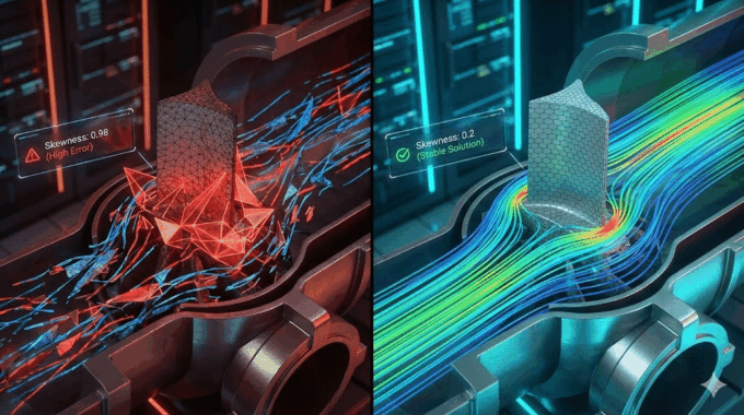
- Computational Domain Discretization (Meshing): This is arguably the most critical step. We divide the fluid volume into millions of small control volumes (cells).
- Expert Insight: We often use polyhedral meshes for complex tank geometries. They offer better convergence and accuracy with fewer cells compared to traditional tetrahedral meshes. Furthermore, a Grid Independence Study (Mesh Convergence) is non-negotiable. We run the simulation at increasing mesh densities to ensure the results are independent of the grid size.
- Physics Setup: Water flow in treatment plants is almost always turbulent. We select the appropriate turbulence model—typically turbulence model selection ($k-\epsilon$ vs. $k-\omega$)—and define the physics, such as multiphase interactions for sludge or species transport for chlorine.
- Post-Processing: Once the solver converges, we extract the data. This isn’t just about pretty pictures; it’s about quantitative metrics like velocity vectors, pressure drops, and concentration profiles.
Why is Optimizing Chlorine Contact Tanks Vital for Cost Reduction?

The Chlorine Contact Tank (CCT) is perhaps the most heavily simulated unit in the industry, and for good reason: the ROI is immediate. The primary goal of a CCT is to hold water for a specific time to ensure pathogen inactivation (Ct value).
However, most unoptimized tanks suffer from severe hydraulic short-circuiting reduction issues.
The Problem: Short-Circuiting and Dead Zones
Imagine a serpentine tank where the water moves fast around the bends but stands still in the corners.
- Short-Circuiting: Fast-moving water exits too early. To kill the bacteria in this “fast water,” you must increase the chlorine dose for all the water.
- Dead Zones (Dead zone quantification): Stagnant areas where water sits for hours, potentially forming harmful Disinfection By-Products (DBPs) like trihalomethanes.
The CFD Solution
Using Ansys Fluent water treatment applications, we simulate the transport of a passive scalar (a virtual dye) through the tank. This reveals exactly where the baffles are failing. We can then virtually install turning vanes, porous baffles, or modify the aspect ratio of the channels to force a plug-flow regime.
Industry Insight: We successfully optimized a CCT for a municipal client where CFD analysis revealed that 30% of the tank volume was dead space. By adding simple localized baffling, we improved the baffling factor significantly, allowing them to reduce chlorine usage by 25% while maintaining compliance.
How Do We Calculate Residence Time Distribution (RTD) Using CFD?

To quantify efficiency scientifically, we move beyond velocity contours and look at Residence Time Distribution (RTD) analysis. This is the gold standard for validating hydraulic efficiency.
In the simulation, we inject a virtual pulse of tracer at the inlet (time zero) and monitor its concentration at the outlet over time. This generates the E-curve (Exit Age Distribution).
Key metrics we extract from this analysis include:
- T10: The time at which 10% of the tracer has passed through the outlet. This is the critical value for regulatory compliance because it represents the “fastest” path through the tank.
- Baffling Factor (BF): This is the ratio of T10 to the Theoretical Retention Time (Volume divided by Flow Rate).
- Tail of the Curve: A long tail in the distribution indicates dead zones where the tracer (and water) is getting trapped.
In an ideal plug-flow reactor, the Baffling Factor is 1.0. In a poorly mixed tank, it might be 0.3. CFD for water treatment allows us to iterate the design until the BF approaches 0.8 or higher. The visual output of this analysis is often a “washout” animation, showing the tracer concentration decaying over time. If the simulation shows pockets of high concentration remaining long after the main pulse has left, we have identified a dead zone that requires immediate re-engineering.
Can CFD Improve Sedimentation and Clarifier Performance?

While CCTs are single-phase problems, clarifiers and sedimentation tanks introduce the complexity of multiphase flow. Here, we are separating solids (sludge) from the liquid.
Sedimentation tank CFD modeling is notoriously difficult because it involves buoyancy-driven flow (temperature differences causing density currents), particle physics (flocculation), and scour (inlet velocities re-suspending solids).
The Eulerian-Eulerian Approach
At MR CFD, we typically utilize an Eulerian-Eulerian multiphase model (often the Granular model) or Eulerian-Lagrangian particle tracking for discrete solids.
- Inlet Optimization: The Energy Dissipating Inlet (EDI) is critical. CFD allows us to design the EDI to slow down the influent jet rapidly to prevent it from “diving” and disturbing the sludge blanket at the bottom.
- Weir Design: We analyze the shear stress at the effluent weirs. If the approach velocity is too high, it carries solids over the weir (carryover). CFD helps us design Stamford baffles or modify weir geometry to ensure uniform withdrawal.
Key Takeaway: A 5% improvement in clarifier capture rate can significantly reduce the load on downstream filters and reduce the volume of sludge requiring dewatering—a major cost center.
What is the ROI of an MR CFD Consulting Project?
Engineering managers often ask: “Is the cost of a high-end simulation justified?” The answer lies in the ratio of simulation cost to operational savings.
An CFD Consulting Service project is an investment in risk mitigation and operational efficiency. Consider the following scenarios:
- Scenario A (Retrofit): A plant spends $15,000 on a CFD study to optimize mixing. The resulting design reduces chemical dosing by 15%. For a mid-sized plant, this can equal $50,000 to $100,000 in annual savings. The ROI is achieved in months.
- Scenario B (Greenfield Design): A construction contractor validates their hydraulic profile using CFD. They discover that the proposed pump configuration causes massive cavitation and uneven flow splitting. Correcting this on paper costs “pennies.” Correcting it after the concrete is poured costs millions.
Our deliverables go beyond colorful charts. We provide quantitative data—reduction in pressure drop, increase in baffling factor, and precise chemical homogeneity indices—that you can take to stakeholders to justify CapEx spend.
How Can Engineers Learn to Perform These Simulations?
While hiring a consultant is the fastest route to a solution, many engineering firms and utility providers are recognizing the value of building in-house CFD capability. However, the learning curve for software like Ansys Fluent or OpenFOAM for hydraulic engineering is steep.
This is where the Ansys Fluent Course bridges the gap. We don’t just teach you which buttons to click; we teach you the physics of water treatment simulation.
Our training modules cover:
- Setting up multiphase flow in clarifiers.
- Validating turbulence model selection.
- Post-processing RTD curves and analyzing hydraulic efficiency.
By combining our consulting expertise with our educational resources, we ensure that the water industry is equipped with the advanced tools necessary to meet the environmental challenges of the next century.
Frequently Asked Questions about Water Treatment CFD
How accurate is CFD for water treatment compared to physical testing?
Modern CFD, when validated with proper Grid Independence Studies and correct turbulence models (like Realizable $k-\epsilon$), typically achieves results within 5-10% of physical experiments. This accuracy is sufficient for engineering decisions and comes at a fraction of the cost and time required for physical prototyping or tracer testing on live operational tanks. We always aim to validate against empirical data whenever site data is available.
Can CFD simulation reduce chemical usage in wastewater plants?
Yes. By identifying hydraulic short-circuiting reduction opportunities and optimizing baffle designs, CFD ensures chemicals mix uniformly with the water. This increases the contact efficiency, allowing operators to reduce dosing safety margins. In many cases, Chlorine contact tank optimization can lower chemical consumption by 15-25%, significantly lowering OPEX and improving the environmental footprint of the facility.
What is the best turbulence model for clarifier simulation?
For large settling tanks, the standard $k-\epsilon$ or Realizable $k-\epsilon$ models are often used due to their robustness and computational economy. However, for regions with high streamline curvature, flow separation, or near-wall analysis (such as flow over a weir), the SST $k-\omega$ model may offer better accuracy. The choice depends heavily on the specific physics of the clarifier being analyzed.
How long does a typical CFD consulting project for a treatment plant take?
A standard project with MR CFD, including geometry cleanup, meshing, solving, and a comprehensive report, typically takes 2 to 4 weeks depending on the complexity of the physics involved. Simpler hydraulic profiles can be done faster, while complex multiphase reaction kinetics may take longer to converge and validate. We work closely with client timelines to ensure data is available before critical design reviews.
Do I need a supercomputer to run water treatment CFD simulations?
For complex multiphase flows or large-scale full-plant simulations, High-Performance Computing (HPC) is highly recommended to manage the millions of mesh cells required. MR CFD offers HPC services to ensure fast turnaround times for heavy simulations, allowing clients without supercomputers to benefit from high-fidelity analysis without the capital investment in hardware.
Related Posts
Errors Occurring in Simulations with ANSYS Fluent: A Technical Guide to Convergence & Stability
ANSYS Fluent simulates engineering problems based on the Finite Volume Method (FVM). Consequently, the errors…
How Ansys HPC Servers Accelerate Your Fluent Dynamic Simulations
We have all been there. You hit “Calculate” on a transient simulation, and the estimated…

Ansys HPC Case Study: Accelerating a 120-Million Cell Simulation Using MR CFD’s Ansys HPC Service
In the high-stakes world of aerodynamics, fidelity is everything. But as engineers, we often hit…

Comments (0)