CFD Project Outsourcing: What Files, Reports, and Results Should You Expect?
When engineering teams decide to outsource CFD simulation, the conversation almost always starts with capability and cost — and almost never starts with deliverables. That is a costly oversight. The real measure of a CFD project outsourcing engagement is not whether the simulation ran, but whether you received everything you need to trust, reproduce, defend, and build upon the results. At MR CFD, we have structured hundreds of simulation engagements across industries including aerospace, HVAC, automotive, energy, and biomedical engineering — and the single most common source of client dissatisfaction inherited from previous vendors is not inaccurate physics. It is incomplete, undocumented, and non-reproducible deliverable packages.
This guide defines the professional CFD project deliverable standard — file by file, section by section — so that engineering managers, R&D leads, and procurement teams can evaluate vendors with precision, set contractual expectations before project kickoff, and recognize immediately when a simulation provider is cutting corners. Whether you are outsourcing your first CFD simulation project or auditing your current vendor’s output, this is the checklist you need.
Submit your project details below:
Why the Deliverable Standard Defines the Value of Any CFD Outsourcing Engagement
Simulation accuracy is table stakes. Any competent CFD engineer can set up a converged RANS solution. What separates a professional CFD consulting firm from a commodity simulation service is the completeness, transparency, and usability of everything delivered after the solver finishes. When you outsource CFD simulation, you are not buying computation time — you are buying engineering intelligence that your organization can act on, build from, and defend to regulators, clients, or internal stakeholders.

From an ROI perspective, the deliverable package determines whether your investment produces a one-time output or a reusable engineering asset. A complete deliverable set allows your team to re-run parametric studies, validate design iterations, and onboard new engineers without starting from scratch. An incomplete one locks you into perpetual dependency on the original vendor — or forces you to rebuild from zero at your next project phase.
The Hidden Cost of Incomplete CFD Deliverables
Incomplete CFD simulation deliverables carry costs that rarely appear in the original project invoice but consistently show up downstream. Consider the following scenarios that we have encountered directly in our simulation engagements:
- A manufacturer receives a pressure drop report but no mesh file and no
.casfile. Six months later, a design change requires re-running the simulation. The original vendor is unavailable. The entire meshing and setup process must be repeated — at full cost. - A product certification team submits CFD results to a regulatory body. The reviewer asks for the mesh independence study and convergence proof. Neither was documented. The submission is rejected. A re-engagement with the vendor costs both time and budget.
- An R&D team inherits a simulation from a freelance engineer. There are no documented boundary conditions, no turbulence model selection rationale, and no validation against experimental data. The results cannot be trusted for design decisions without full re-validation.
These are not edge cases. They are predictable consequences of engaging vendors who treat deliverables as an afterthought. The engineering liability exposure alone — particularly in regulated industries such as aerospace, medical devices, and nuclear — makes incomplete deliverables a genuine risk management issue, not merely an inconvenience.
What Separates a Professional CFD Firm from a Freelance Simulation Run
The structural difference between a professional CFD firm and a low-cost freelance simulation run is not always visible in the post-processing images. Both can produce a colorful velocity contour plot. The difference is what sits behind that image.
| Deliverable Element | Professional CFD Firm | Freelance / Low-Cost Vendor |
|---|---|---|
| Cleaned CAD geometry files | ✅ Provided in STEP/IGES/Parasolid | ❌ Often not provided |
| Mesh file with quality report | ✅ MSH/CGNS + skewness/orthogonality metrics | ❌ Mesh rarely handed over |
ANSYS Fluent .cas + .dat files | ✅ Full solver package | ❌ Withheld or not archived |
| UDF scripts (if applicable) | ✅ Documented and commented | ❌ Missing or undocumented |
| Mesh independence study | ✅ Multi-level GCI analysis | ❌ Single mesh, no documentation |
| Validation against benchmark data | ✅ Compared to experimental/published data | ❌ No validation section |
| Engineering report with methodology | ✅ Full solver transparency | ❌ Slide deck with images only |
| Design recommendations | ✅ Actionable conclusions | ❌ “Results are attached” |
A freelance simulation run produces output. A professional CFD consulting engagement produces an engineering asset. The distinction is critical when you are making design decisions, submitting to clients, or preparing for product certification.
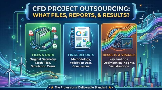
The Complete CFD Project Deliverable Checklist: File by File
A complete CFD simulation deliverables checklist covers five distinct asset categories. Each serves a different function in your engineering workflow, and the absence of any one of them degrades the overall value of the project. Below is the authoritative breakdown of what every CFD project outsourcing package should contain.
Geometry and CAD Files — What Format and What Level of Cleanup?
Geometry files are the foundation of every simulation, and yet they are among the most commonly omitted deliverables. A professional vendor should return the geometry in a cleaned, simulation-ready state — not the raw, feature-heavy CAD model you submitted for manufacturing.
What you should receive:
- Defeatured and simplified CAD geometry — small fillets, threads, logos, and manufacturing features that do not affect flow physics should be suppressed or removed, and this cleaned version should be documented and returned
- Supported neutral formats — at minimum, STEP (.stp), IGES (.igs), and ideally Parasolid (.x_t) for maximum CAD software compatibility
- Named geometry components — fluid domains, solid regions, inlet/outlet surfaces, and wall boundaries should be clearly named and organized for re-use
- A geometry modification log — documenting what was changed from the original CAD and why, so your design team understands what simplifications were made
Why does this matter for future design iterations? Because when your team needs to run a variant study — a modified inlet geometry, a revised heat exchanger fin pitch, or an updated turbine blade profile — you need a clean, simulation-ready baseline. If the vendor never returns the defeatured geometry, you are rebuilding that baseline every time.
Mesh Files — Structured, Unstructured, and Quality Metrics
The mesh file is one of the most technically significant deliverables in any CFD project, and one of the most frequently withheld by low-quality vendors. Generating a high-quality mesh for a complex geometry is often the most labor-intensive part of the entire simulation workflow. A vendor who withholds the mesh is protecting their labor investment at your expense.
What you should receive:
- Mesh file in a portable format — MSH (.msh) for ANSYS Fluent native use, or CGNS (.cgns) for solver-agnostic portability
- Mesh quality report documenting:
- Maximum skewness (should be below 0.85 for most applications; below 0.95 absolute maximum)
- Minimum orthogonal quality (should be above 0.15; ideally above 0.2)
- Maximum aspect ratio (context-dependent, but flagged values should be explained)
- y⁺ values at wall boundaries, confirming appropriate wall treatment for the chosen turbulence model
- Mesh independence study documentation — results from at least three mesh refinement levels showing how key output variables (pressure drop, drag coefficient, Nusselt number, etc.) converge with mesh density
- Grid Convergence Index (GCI) analysis per ASME V&V 20 methodology, quantifying the numerical error attributable to spatial discretization
Without the mesh independence study, you cannot know whether the results are mesh-dependent. A simulation that has not been proven mesh-independent is, by definition, a simulation with an unquantified numerical error — and that error could be larger than the physical effect you are trying to measure.
ANSYS Fluent Case and Data Files — The Core Simulation Package
The ANSYS Fluent .cas and .dat files are the most critical computational deliverables in any ANSYS-based CFD project outsourcing engagement. The .cas file contains the complete solver setup — mesh, boundary conditions, turbulence model, solver settings, material properties, and all physics definitions. The .dat file contains the converged solution field — every velocity, pressure, temperature, and turbulence quantity at every mesh node.
Together, these files allow you to:
- Re-open the simulation in ANSYS Fluent and reproduce any result shown in the report
- Extract additional post-processing quantities that were not included in the original deliverable
- Run parametric variations — change a boundary condition, material property, or operating point and re-solve without rebuilding the setup
- Onboard new engineers — any qualified CFD engineer can open the
.casfile and understand the full simulation setup without relying on the original vendor
What you should receive:
.casfile — complete solver case with all settings preserved.datfile — converged solution data (or multiple.datfiles for transient simulations at specified time steps)- Documented boundary condition summary — inlet velocities/mass flow rates, outlet conditions, wall thermal boundary conditions, symmetry/periodic conditions, all explicitly stated with units
- Solver settings documentation — discretization schemes, pressure-velocity coupling algorithm (SIMPLE, SIMPLEC, COUPLED), under-relaxation factors, convergence criteria
- UDF scripts — if any User-Defined Functions were used for custom boundary conditions, source terms, or material properties, the fully commented
.csource files must be included
A vendor who delivers only images and a PDF report — without the .cas and .dat files — has given you a photograph of the simulation, not the simulation itself.
Post-Processing Output Files — Contours, Vectors, Animations, and Raw Data
Post-processing deliverables are what most clients see first, but they should be the last thing you evaluate — because their value depends entirely on whether the underlying simulation is valid. Assuming it is, a complete post-processing package should include both visual outputs and exportable numerical data.
Visual outputs you should receive:
- Velocity contour plots — on relevant cross-sections, colored by magnitude with clearly labeled scales and units
- Pressure field plots — static and total pressure distributions on surfaces and through-plane sections
- Temperature distribution plots — for thermal simulations, surface and volume temperature fields
- Streamline and pathline visualizations — 3D streamlines showing flow structure, recirculation zones, and separation regions
- Wall shear stress and y⁺ distribution plots — confirming boundary layer resolution
- Transient animations — for time-dependent simulations,
.avior.mp4animations of key flow variables over the simulation period
Numerical data you should receive:
- Exported CSV or Excel tables — of all reported quantities (e.g., pressure drop vs. flow rate, heat transfer coefficient distribution, force coefficients) so your team can perform independent analysis
- Monitor point history files — showing how key quantities evolved during the simulation, confirming convergence behavior
- Residual convergence plots — visual proof that all governing equations converged to the specified criteria
The exportable numerical data is particularly important. Post-processing images are useful for presentations and reports, but engineering decisions require numbers — and those numbers should be in a format your team can analyze independently.
The CFD Simulation Report type
The CFD engineering report is the document that transforms simulation data into engineering knowledge. It is what you submit to clients, present to management, file with regulatory bodies, and reference in future projects. A professional report is not a collection of colorful images with captions. It is a structured technical document that makes the simulation results defensible, reproducible, and actionable.

A professional CFD engineering report should run between 20 and 60 pages depending on project complexity, and must contain the following sections as a minimum standard.
Validation and Verification Section — Why This Is Non-Negotiable
Verification and Validation (V&V) is the process by which a simulation is proven to be both numerically correct (verification) and physically representative (validation). The ASME V&V 20 standard provides the industry-accepted framework for CFD validation in engineering applications, and its absence from a deliverable is one of the clearest signals of an underqualified vendor.
Verification confirms that the numerical solution is mathematically correct — that the solver is solving the governing equations accurately for the given mesh and discretization scheme. The primary verification evidence is:
- Mesh independence study results with GCI quantification
- Residual convergence plots showing that all equations converged below the specified tolerance
- Conservation checks — confirming mass, momentum, and energy balances close to within acceptable tolerances
Validation confirms that the simulation accurately represents the physical phenomenon being modeled. This requires comparison against:
- Experimental data — wind tunnel measurements, PIV data, thermocouple readings, pressure tap data
- Published benchmark cases — well-established test cases from the literature (e.g., lid-driven cavity, backward-facing step, Ahmed body) used to validate solver setup for a given flow regime
- Analytical solutions — for simplified geometries where closed-form solutions exist (e.g., Poiseuille flow, Graetz problem)
A report that presents results without a validation section is asking you to trust the simulation on faith. In professional engineering practice, that is not acceptable — and in regulated industries, it is not permissible.
Methodology, Assumptions, and Solver Settings Documentation
Full solver methodology disclosure is what makes a simulation reproducible. Without it, even the most accurate results cannot be independently verified or extended to new design variants.
What the methodology section must include:
- Turbulence model selection with rationale — Why was k-omega SST chosen over k-epsilon realizable? What flow features (separation, adverse pressure gradient, wall-bounded flow) drove the selection? What are the known limitations of the chosen model for this application?
- Boundary condition documentation — Every inlet, outlet, wall, symmetry, and periodic boundary condition stated explicitly with numerical values and units. Inlet turbulence intensity and length scale specifications must be included.
- Material property definitions — Fluid and solid material properties, including temperature-dependent properties if applicable, with sources cited
- Solver settings — Pressure-velocity coupling algorithm, spatial discretization schemes for each equation (momentum, energy, turbulence), temporal discretization scheme for transient cases, time step size and justification
- Convergence criteria — The residual thresholds used to define convergence for each equation, and the monitor quantities used to confirm physical convergence (not just residual convergence)
- Assumptions and simplifications — Every simplification made — steady-state assumption, symmetry assumption, incompressible flow assumption, neglected radiation heat transfer — must be stated and justified
This level of documentation is what separates a defensible simulation from a black-box result. It allows any qualified engineer to open the .cas file, read the methodology section, and independently confirm that the setup is consistent with the reported approach.
Engineering Conclusions and Design Recommendations
The final section of a professional CFD engineering report should be the most valuable section for non-simulation engineers — and it is the section most commonly missing from low-quality deliverables. Raw numbers are not conclusions. Conclusions are engineering judgments derived from the data.
What actionable output looks like:
- Specific performance metrics with context — “The pressure drop across the heat exchanger at the design flow rate is 1,240 Pa, which is 18% higher than the target specification of 1,050 Pa. The primary contributor is the flow maldistribution in the second pass, where three channels carry 60% of the total flow.”
- Flagged risk zones — Identified regions of high wall shear stress, recirculation, thermal hot spots, or flow instability that represent design risks, with quantified severity
- Parametric sensitivity findings — If multiple operating conditions were simulated, which parameters have the greatest influence on performance?
- Specific design modification recommendations — Not “consider redesigning the inlet” but “increasing the inlet manifold diameter from 40 mm to 55 mm is projected to reduce flow maldistribution by approximately 35% based on the observed velocity distribution pattern”
- Limitations and next steps — What assumptions limit the current results, and what additional simulation or experimental work would increase confidence?
This is the difference between a vendor who runs simulations and a vendor who delivers engineering intelligence.
Submit your project details below:
Red Flags | What a Low-Quality CFD Outsourcing Vendor Will NOT Deliver
When evaluating a professional CFD vendor, the absence of certain deliverables is as informative as their presence. The following red flags are reliable indicators of an underqualified or corner-cutting simulation provider. Use this as your vendor audit checklist before signing any project agreement.
Top-level red flags:
- ❌ No mesh file provided — “We keep the mesh on our systems”
- ❌ No
.casor.datfiles — “We only deliver the report and images” - ❌ No mesh independence study — “We used a fine mesh, so it’s fine”
- ❌ No residual convergence plot — results presented without proof of convergence
- ❌ No validation section in the report — results compared to nothing
- ❌ No boundary condition documentation — inlet conditions described vaguely or not at all
- ❌ No turbulence model justification — model selected without explanation
- ❌ No UDF files for custom physics — “The code is proprietary”
- ❌ Report consists of images only — no methodology, no numbers, no engineering conclusions
Missing Mesh Independence Study or Convergence Proof
The mesh independence study is the most fundamental quality assurance step in any CFD workflow. Its absence does not mean the results are wrong — it means there is no evidence that they are right.
When a mesh independence study is not performed, the reported results could be carrying a discretization error of anywhere from 1% to 30% or more, depending on the flow complexity and the mesh density used. For engineering decisions — particularly those involving safety margins, regulatory submissions, or product performance guarantees — that unquantified error is professionally unacceptable.
The Grid Convergence Index (GCI) method, published by Roache and formalized in the ASME V&V 20 standard, provides a rigorous, quantitative estimate of the numerical uncertainty due to spatial discretization. A vendor who does not perform this analysis is either unaware of the standard (a competence issue) or aware of it and choosing to skip it to save time (an ethics issue). Neither is acceptable.
Similarly, residual convergence must be demonstrated — not assumed. A simulation that appears visually stable but has residuals that have not dropped by at least three orders of magnitude, or where monitored quantities (e.g., drag force, outlet temperature) have not reached a stationary value, is not a converged simulation. It is a partially-run simulation presented as complete.
No Validation Against Experimental or Published Data
Unvalidated CFD results are a liability, not an asset. A simulation that has never been compared to experimental measurements or established benchmark data is a mathematical model whose physical accuracy is entirely unknown.
Validation is not always straightforward — it requires access to experimental data, careful selection of appropriate benchmark cases, and honest reporting of discrepancies. This is precisely why low-quality vendors skip it. It takes time, it requires expertise, and it occasionally reveals that the simulation needs to be revised.
Here is how to spot when a vendor is skipping validation:
- The report contains no references to experimental data or published benchmark cases
- When asked about validation, the vendor responds with “the simulation was run with best practices” — a non-answer
- The vendor claims the geometry is “too complex” for validation — but validation can always be performed on a simplified representative geometry
- The report shows only one operating condition — making it impossible to check whether trends match physical expectations
An unvalidated simulation is not a deliverable you can defend. Before committing budget to a CFD outsourcing vendor, ask explicitly: “What experimental or published data will you use to validate this simulation, and how will that validation be documented in the report?”
How MR CFD Structures Its CFD Project Deliverables
At MR CFD, our CFD project deliverable framework was built around a single principle: every client should receive everything they need to trust, reproduce, extend, and defend their simulation results — without ever needing to come back to us for the basics. That principle is not altruistic. It is the engineering standard that makes our work defensible, our clients successful, and our reputation durable.

Our CFD Consulting Services are structured to produce deliverable-complete project packages across all simulation domains — from external aerodynamics and internal flow systems to conjugate heat transfer, multiphase flow, and reactive flow simulations.
From Geometry Intake to Final Report — MR CFD’s Project Workflow
In our project workflow, every engagement follows a structured, stage-gated process designed to ensure that deliverable quality is built in at every step — not assembled at the end.
Stage 1 — Geometry Intake and Review We receive the client’s CAD model and perform a geometry audit: identifying features that require defeature, surfaces that need repair, and fluid domain extraction requirements. The cleaned, simulation-ready geometry is documented and archived as a primary deliverable.
Stage 2 — Meshing and Quality Validation Our meshing engineers generate the computational mesh using ANSYS Meshing or ANSYS Fluent meshing tools, with boundary layer inflation appropriate to the chosen turbulence model and target y⁺ values. Mesh quality metrics are checked against project-specific thresholds. The mesh independence study is performed before the production simulation begins — not as an afterthought.
Stage 3 — Solver Setup and Documentation The ANSYS Fluent case is set up with full documentation of every boundary condition, material property, turbulence model selection, and solver setting. This documentation is written during setup, not reconstructed from memory after the fact.
Stage 4 — Simulation Execution and Convergence Monitoring Simulations are executed on our managed HPC infrastructure, with residual and monitor quantity convergence tracked throughout. Convergence is confirmed before post-processing begins.
Stage 5 — Validation Results are compared against available experimental data, published benchmark cases, or analytical solutions. Discrepancies are documented, explained, and — where significant — addressed through model refinement.
Stage 6 — Post-Processing and Report Writing Post-processing outputs are generated systematically, covering all relevant flow variables and surfaces. The engineering report is written to the full professional standard described in this article, including methodology, V&V documentation, and design recommendations.
Stage 7 — Deliverable Packaging and Handoff All deliverables — geometry files, mesh files, .cas and .dat files, UDF scripts, post-processing outputs, CSV data exports, and the final engineering report — are packaged and transferred to the client with a deliverable manifest confirming completeness.
HPC-Backed Simulation Quality: How Managed ANSYS Fluent Infrastructure Affects Result Fidelity
Computational resources are not a background detail in CFD project outsourcing — they directly determine what quality of result is achievable within a given timeline.
Mesh resolution is the most direct connection. A high-quality mesh for a complex industrial geometry may require 20 to 100 million cells. On a standard workstation, that simulation may require weeks. On MR CFD’s managed HPC infrastructure — configured specifically for ANSYS Fluent parallel processing — the same simulation runs in hours to days, making it economically feasible to perform the mesh independence study, run multiple operating conditions, and iterate on design variants within a reasonable project timeline.
Transient simulation fidelity is similarly resource-dependent. Large Eddy Simulation (LES) and Detached Eddy Simulation (DES) — the high-fidelity turbulence approaches required for applications involving strong flow unsteadiness, aeroacoustics, or mixing — are computationally prohibitive on desktop hardware. HPC access makes these approaches available for industrial-scale geometries.
Turnaround time is the practical benefit that clients experience most directly. Faster computation means more design iterations per project budget, faster response to design changes, and shorter time-to-decision for R&D teams working under product development deadlines.
Our ANSYS HPC PACK are available to clients who need high-performance computation for their own ANSYS Fluent simulations, as well as being the infrastructure backbone of every MR CFD consulting engagement.
Start Your CFD Project the Right Way — Get a Free Feasibility Assessment
If you are evaluating vendors for a CFD simulation outsourcing project — or if you have received a deliverable package from a previous vendor and are not sure whether it meets professional standards — the most direct next step is a conversation with our senior engineering team.
At MR CFD, we offer a Free Feasibility Assessment for new project inquiries. In this assessment, we review your project scope, identify the appropriate simulation methodology, confirm what deliverables are applicable to your specific application, and provide an honest evaluation of timeline and complexity — before any commitment is made.
There is no obligation, no sales pressure, and no generic proposal. What you get is a direct technical conversation with engineers who have run the type of simulation you are evaluating.
Submit your project details below:
Frequently Asked Questions About CFD Project Outsourcing Deliverables
What files should I receive when I outsource a CFD simulation project?
A complete CFD project outsourcing deliverable package should include five categories of files:
- Geometry files — cleaned and defeatured CAD in STEP, IGES, or Parasolid format
- Mesh files — MSH or CGNS format with an accompanying mesh quality report and mesh independence study documentation
- Solver files — ANSYS Fluent
.cas(case) and.dat(data) files with all boundary conditions, solver settings, and UDF scripts if applicable - Post-processing outputs — contour plots, vector fields, streamline visualizations, transient animations, and exportable CSV/Excel numerical data
- Engineering report — a full technical document covering methodology, V&V documentation, convergence proof, and actionable design recommendations
The absence of any of these categories is a legitimate reason to request completion from your vendor before accepting the deliverable.
Is it standard practice to receive the ANSYS Fluent .cas and .dat files after project completion?
Yes — receiving the ANSYS Fluent .cas and .dat files is the professional standard for any ANSYS-based CFD consulting engagement. These files are the complete computational record of the simulation. The .cas file contains the full solver setup; the .dat file contains the converged solution. Without them, you cannot reproduce the results, extract additional quantities, or run design variants independently.
A vendor who withholds these files — citing proprietary methods or system limitations — is restricting your engineering autonomy. In most professional engagements, client ownership of the simulation files should be explicitly stated in the project agreement. If a vendor refuses to include this in the contract, treat it as a significant red flag.
What does a professional CFD engineering report include, and how long should it be?
A professional CFD engineering report should include: project scope and objectives, geometry and meshing methodology, turbulence model selection with rationale, boundary condition documentation, solver settings, mesh independence study results with GCI analysis, residual convergence proof, validation against experimental or published benchmark data, post-processing visualizations with labeled scales and units, exportable numerical data tables, engineering conclusions, and specific design recommendations.
Report length typically ranges from 20 to 60 pages for standard industrial projects. Highly complex multi-physics simulations, transient analyses, or parametric studies with multiple operating conditions may justify longer reports. A report shorter than 15 pages for any non-trivial simulation is almost certainly missing critical documentation.
How do I know if a CFD vendor has performed a proper mesh independence study?
A proper mesh independence study should appear as a dedicated section in the engineering report, presenting results from at least three mesh refinement levels (coarse, medium, fine — or fine, finer, finest). The section should show how one or more key output variables — such as pressure drop, drag coefficient, or average Nusselt number — change as mesh density increases.
The Grid Convergence Index (GCI) method, per ASME V&V 20, should be used to quantify the remaining numerical uncertainty. A GCI value below 1–2% for the fine mesh solution indicates that further mesh refinement would produce negligible change in the result.
If the report does not contain this section — or if the vendor states “we used a fine mesh” without quantitative evidence — the mesh independence has not been properly demonstrated. Ask specifically for the GCI table before accepting the deliverable.
What is the difference between CFD verification and validation, and should both be in my deliverable?
Verification and validation are distinct processes that together confirm the scientific credibility of a CFD simulation:
- Verification asks: Is the simulation solving the equations correctly? Evidence includes mesh independence studies, residual convergence plots, and conservation balance checks. It confirms numerical accuracy.
- Validation asks: Is the simulation representing the real physics correctly? Evidence includes comparison against experimental measurements, published benchmark data, or analytical solutions. It confirms physical accuracy.
Both should be documented in your deliverable. Verification without validation means you have a numerically stable simulation whose physical accuracy is unknown. Validation without verification means the comparison to experimental data may be contaminated by numerical errors. A complete, defensible simulation requires both.
Can I re-run or modify the simulation myself after receiving the project files?
Yes — provided you receive the complete ANSYS Fluent .cas and .dat files, along with documented boundary conditions and any UDF scripts, you can re-open the simulation in ANSYS Fluent and modify it independently. You can change boundary conditions, material properties, solver settings, or geometry (with re-meshing) and re-run the simulation without any involvement from the original vendor.
This is one of the core reasons why complete file delivery is so important. If you plan to run design iterations internally, or if you have ANSYS Fluent licenses and engineering staff who can operate the solver, the project files are the asset that enables that capability. If you need to build internal CFD capability, MR CFD’s CFD training Courses provide structured training for engineers at all levels.
What are the most common red flags that a CFD outsourcing vendor is underqualified?
Based on our engineering practice and the projects we have inherited from previous vendors, the most reliable red flags for an underqualified CFD outsourcing provider are:
- No mesh independence study — the single most common indicator of shortcuts taken
- No residual convergence documentation — results presented without proof of solver convergence
- No validation section — simulation results compared to nothing
- Refusal to provide
.casand.datfiles — restricts reproducibility and client autonomy - Vague or missing boundary condition documentation — “standard inlet conditions” is not documentation
- No turbulence model justification — model selected without explanation of why it is appropriate for the flow regime
- Report consists only of images — no methodology, no numbers, no engineering conclusions
- Extremely short turnaround — a complex simulation completed in 24 hours almost certainly skipped V&V steps
- No GCI or numerical uncertainty quantification — ASME V&V 20 compliance is the professional standard
Any combination of three or more of these flags should prompt serious reconsideration of the vendor relationship.
How does MR CFD package and deliver completed CFD simulation projects?
In our simulation engagements, MR CFD delivers a complete, manifest-confirmed project package that includes: cleaned geometry files in neutral CAD formats, high-quality mesh files with documented quality metrics and mesh independence study results, ANSYS Fluent .cas and .dat files with full solver transparency, all post-processing outputs including contour plots, streamline visualizations, transient animations, and CSV data exports, and a structured engineering report covering full methodology, V&V documentation, convergence proof, and specific design recommendations.
All simulations are executed on our managed HPC infrastructure configured for ANSYS Fluent parallel processing, ensuring that mesh resolution, transient fidelity, and parametric coverage are not limited by computational hardware constraints. Every deliverable package is reviewed by a senior engineer before client handoff.
To discuss your specific project requirements and receive a Free Feasibility Assessment, submit your details using the form below.
Submit your project details below:
Conclusion
CFD project outsourcing is a significant engineering and financial investment. The quality of that investment is determined not by the complexity of the simulation, but by the completeness, transparency, and usability of everything you receive at the end. A professional CFD project deliverable package — geometry files, mesh files, ANSYS Fluent .cas and .dat files, post-processing outputs, and a full engineering report with V&V documentation and design recommendations — is not a premium add-on. It is the minimum standard of professional practice.
Use the checklist and red flag criteria in this article to evaluate any vendor before committing budget, and to audit any deliverable before accepting it. If a vendor cannot meet this standard, the downstream costs of incomplete deliverables will exceed any short-term savings on the project fee.
At MR CFD, this standard is not aspirational — it is operational. Every project we deliver is built around the principle that our clients should receive everything they need to own, reproduce, and build upon their simulation results. If you are ready to start your next CFD simulation project on the right foundation, we are ready to talk.
Submit your project details below:
Related Posts
ANSYS Fluent Consulting: Get Defensible, Audit-Ready Simulation Results
You need ANSYS Fluent results that can survive scrutiny — a design review, a client…
CFD Simulation Services for Product Design: Reduce Prototyping Cost Before Manufacturing
In modern product development, the most expensive mistakes are often discovered after money has already…

CFD Consulting Services for Industries: When Should Industrial Teams Hire Experts?
A CFD model can influence a pump redesign, an HVAC layout, a combustion chamber, a…
Comments (0)