3-D Airfoil CFD Simulation, ANSYS Fluent Training
$60.00 Student Discount
This project will study an incompressible isothermal air flow adjacent to a 3-D airfoil.
Click on Add To Cart and obtain the Geometry file, Mesh file, and a Comprehensive ANSYS Fluent Training Video.To Order Your Project or benefit from a CFD consultation, contact our experts via email ([email protected]), online support tab, or WhatsApp at +44 7443 197273.
There are some Free Products to check our service quality.
If you want the training video in another language instead of English, ask it via [email protected] after you buy the product.
Description
3-D Airfoil CFD Simulation
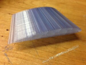
An airfoil is the cross-sectional shape of a wing, a propeller rotor or turbine blade, or sail as seen in cross-section.
An airfoil is a streamlined shape that is capable of generating significantly more lift than drag. Subsonic flight airfoils have a characteristic shape with a rounded leading edge, followed by a sharp trailing edge, often with a symmetric curvature of upper and lower surfaces. Foils of similar function designed with water as the working fluid are called hydrofoils.
In this study, a CFD solver is employed to test an airfoil for ourselves, and the drag and lift force values were calculated by ANSYS Fluent software.
Project Description
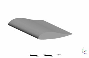
This project is going to study an incompressible isothermal air flow adjacent to a 3-D airfoil. The geometry is a 1-meter airfoil inside a 20-meter wind tunnel. Also, the maximum speed of 10 m/s is selected for the inlet.
Geometry and Mesh
As a numerical study, the initial step towards the modeling is the production of the CAD geometry, depicted below. The blue face is considered the inlet of the domain, while the red face on the other side is considered the outlet.
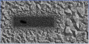
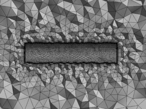
For the current problem, a mesh count of 724,682 elements was created to represent the geometry. Regarding the quality of the mesh, the maximum skewness of 0.93 with an average of 0.28 is a satisfactory mesh for the current problem. In addition, for an interested reader, the quality distribution of mesh is shown as follows. Also, 15 prism layers were added adjacent to both tunnel walls and the airfoil body to calculate the boundary layer accurately.
CFD Simulation Settings
By importing the mesh into the ANSYS FLUENT solver, the calculation procedure is started. The Details of the solution setup are as follows:
Table (1)- Solver Settings
| Solver settings: | |
| Type: | Pressure-based |
| Time setting: | Steady-state |
| Energy: | On |
| Model: | k-w-SST |
| Zone: | Fluid zone: Rectangular Box: Default |
| Boundary conditions: | Airfoil Walls: No-slip
Inlet: velocity inlet: 10 m/s Outlet: pressure outlet FarWalls: Symmetry |
| Solver Properties: | |
| Solution methods: | SIMPLE |
| Pressure interpolation scheme: | Second-Order |
| Momentum: | First -Order |
| Turbulence: | First-Order |
| Relaxation: | Default, Number of Iterations = 1000 |
| Initialization: | Standard > from the inlet |
| Material used: | |
| Fluid: | Air – constant properties
Density: 1.225 kg/(m3) Viscosity: 0.001003 (Pa.s) |
| Monitor: | Drag Value of Plane wall in X-direction: 4.91 (N)
Lift Value of Plane wall in Y-direction: 19.61 (N) |
3-D Airfoil CFD Simulation Results and Discussions
After the solution convergence, they can observe the results through post-processing. Meanwhile, as an assurance of a valid convergence, we monitor the drag and lift values during the solution iterations. In this study, the solution was a converged one when the drag force reached a constant rate and the residuals were below 10-7 values.
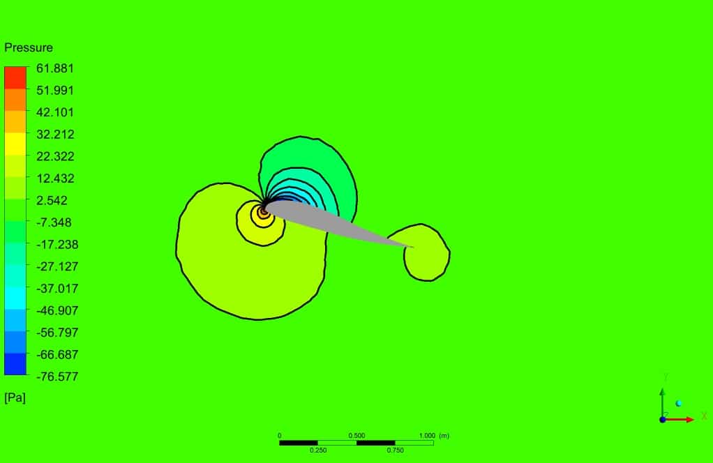
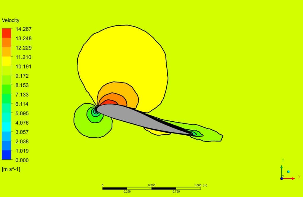
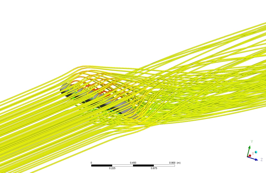
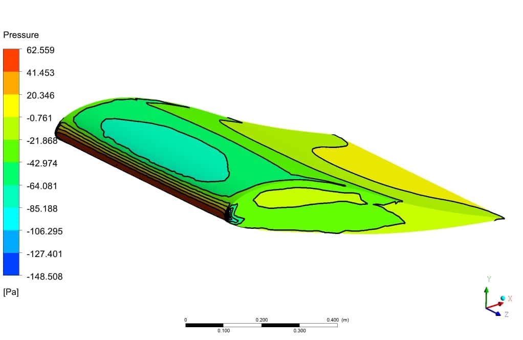
Afterward, the results regarding the pressure and the velocity field are depicted in the below figures. Again, the maximum value of velocity was found at the top surface of the airfoil, while the maximum value of pressure was at the leading edge where the velocity was minimum. Also, the streamlines were shown to give much insight into the problem.
Finally, we calculated the drag and lift force at 4.91 and 19.61 (N), respectively, which was accurate for a 1-meter airfoil with the noted specifications.






Adelia Lindgren –
I appreciate the level of detail in the simulation setup and results. The figures provided deep insight into airfoil behavior in various flow circumstances. Can you recommend this course to someone interested in aerospace simulations?
MR CFD Support –
Thank you for your kind words! We’re glad to hear that you found the course detail-oriented and insightful. Definitely, anyone interested in aerospace simulations or seeking to understand aerodynamics and flow behavior around airfoil structures would benefit from this course. We appreciate your recommendation!
Miss Allison Jast –
The CFD training material was brilliantly detailed, especially the contour and streamline visualizations provided made it exceptionally intuitive to understand complex airflow interactions with the airfoil.
MR CFD Support –
Thank you for your positive feedback! It’s great to hear that the visualizations were helpful in understanding the simulation results. If you have any further questions, feel free to ask. Your success is our goal at MR CFD.
Hal Denesik III –
I am truly amazed by the 3-D Airfoil CFD Simulation empowers us with precise control over aero properties. The convergence to steady measurements of drag and lift provides confidence in the accuracy of results. Fantastic quality and edification from MR CFD Company’s learning product!
MR CFD Support –
Thank you for your kind words and for recognizing the quality of our 3-D Airfoil CFD Simulation. We’re thrilled to hear that our product has provided you with valuable insights and met your expectations. Your satisfaction is our main goal, and we appreciate you taking the time to leave this positive review!
Miss Billie Legros DVM –
The detail in the 3-D Airfoil CFD analysis is clear and shows a great effort. The analysis of lift and drag along with the monitoring of convergence is quite professional. The setup to achieve a well-developed turbulent boundary layer using prism layers is commendable as is the thoughtful selection of a SST k-omega model for the simulation.
MR CFD Support –
We appreciate your in-depth and encouraging review! It’s great to hear that you are satisfied with the level of detail and accuracy in our 3-D Airfoil CFD simulation. We always aim to provide thorough analyses, ensuring our customers can trust in the professionalism and precision of our simulations. Thank you for taking the time to share your positive experience.
Ms. Bert Crooks –
I recently completed the 3-D Airfoil CFD Simulation with the ANSYS Fluent software based on the training provided by MR CFD and I’m thoroughly impressed with the comprehensive and detailed approach. From geometry creation to mesh generation and all the way through to convergence monitoring, this project has significantly enhanced my understanding of aerospace simulations. The results show a convincing representation of aerodynamic forces which aligns perfectly with theoretical expectations. A special shout out for including the k-w-SST turbulence model which closely predicted the realistic physical phenomena encountered by an actual airfoil.
MR CFD Support –
We’re delighted to know that our 3-D Airfoil CFD Simulation training gave you such a valuable insight into aerospace simulations and that you’re satisfied with the results and theoretical alignment. Your mention of the k-w-SST turbulence model’s effectiveness is certainly appreciated; we aim to incorporate realistic modeling for our users’ learning benefits. Thank you for taking the time to share your positive experience!
Gillian Pfannerstill –
The level of detail in the project is reflect applications. Can you tell me about the understanding of airfoil behaviors at different angles of attack?
MR CFD Support –
While the review does not specifically mention simulations at varying angles of attack, the understanding of airfoil behavior for different angles can usually be investigated by setting up separate simulation cases. Each case would have the airfoil at a different orientation with respect to the incoming airflow. These simulations can provide insight into the lift, drag, and moment coefficients at various angles, which are essential for characterizing the airfoil’s aerodynamic performance. Should you be interested in learning more about the effects of angle of attack on airfoil performance, you might want to consider exploring customized simulation services that focus on parametric studies.