Container Effect on Truck Aerodynamic CFD Simulation, ANSYS Fluent Training
Free
- The problem numerically simulates the Container Effect on Truck aerodynamics using ANSYS Fluent software.
- The 3-D geometry is designed in Solidworks and Design Modeler software.
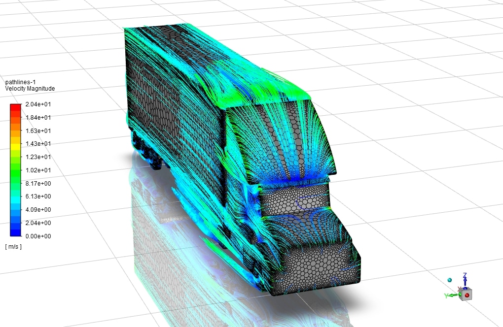
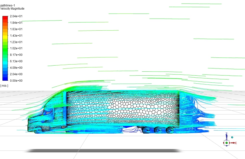
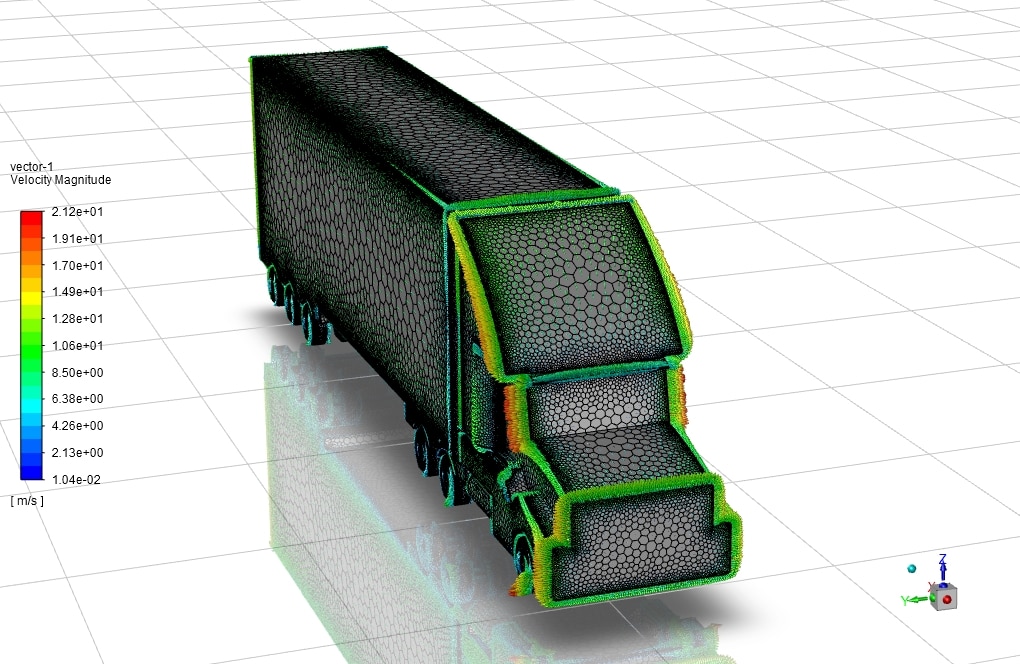
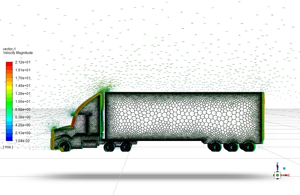
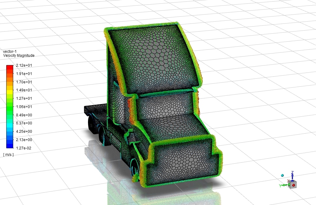
- We used ANSYS Meshing to generate polyhedral mesh; the element number equals 663,127 and 1,095,371 for ‘truck‘ and ‘truck and container,’ respectively.
- Turbulence is modeled with the k-w SST model.
Click on Add To Cart and obtain the Geometry file, Mesh file, and a Comprehensive ANSYS Fluent Training Video.
To Order Your Project or benefit from a CFD consultation, contact our experts via email ([email protected]), online support tab, or WhatsApp at +44 7443 197273.
There are some Free Products to check our service quality.
If you want the training video in another language instead of English, ask it via [email protected] after you buy the product.
Description
Container Effect on Truck Aerodynamic CFD Simulation
description
Aerodynamics is a part of mechanics that is very important in car design. This is even more important when designing a truck; Because these cars have more weight, the air resistance in their movement should be reduced as much as possible to have better forward movement. Drag force means air resistance to forward motion and is one of the most important forces to be considered.
The aerodynamic CFD simulation of the truck and the drag force calculation helps us have a good prediction of different forces, especially the drag force around the truck. This directly impacts the truck’s fuel consumption and is essential from an energy and environmental perspective.
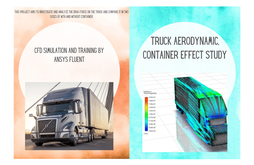
This project aims to investigate and analyze the drag force on the truck and compare it in two cases with and without a container by ANSYS Fluent software.
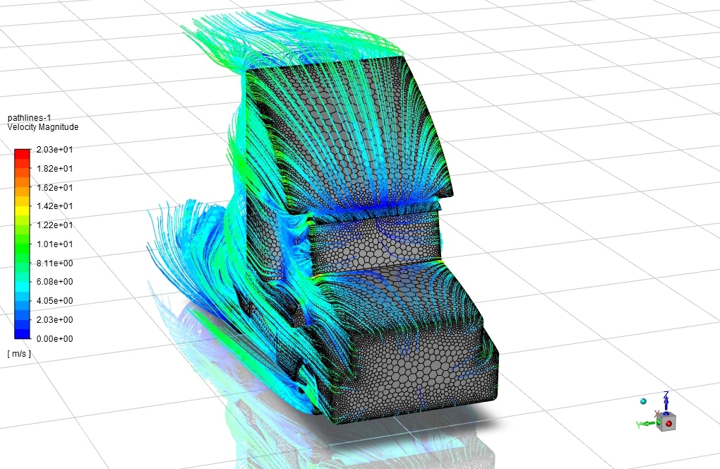
First, the truck’s geometry is designed in Solidworks software and Design Modeler software. The geometry is prepared to create meshing and name selection; then, it is implemented in ANSYS Meshing software. Also, the mesh type is polyhedral, and 663,127 and 1,095,371 elements are produced for ‘truck‘ and ‘truck and container,’ respectively.
.
Container Effect on Truck Aerodynamic CFD Simulation Methodology
The flow simulation and investigation have been done by comparing the two truck modes with and without containers. We chose the k-w SST turbulence model with standard wall function to obtain better results in our simulation. The pressure and momentum coupling method is SIMPLE.
The solver used is pressure-based.
conclusion
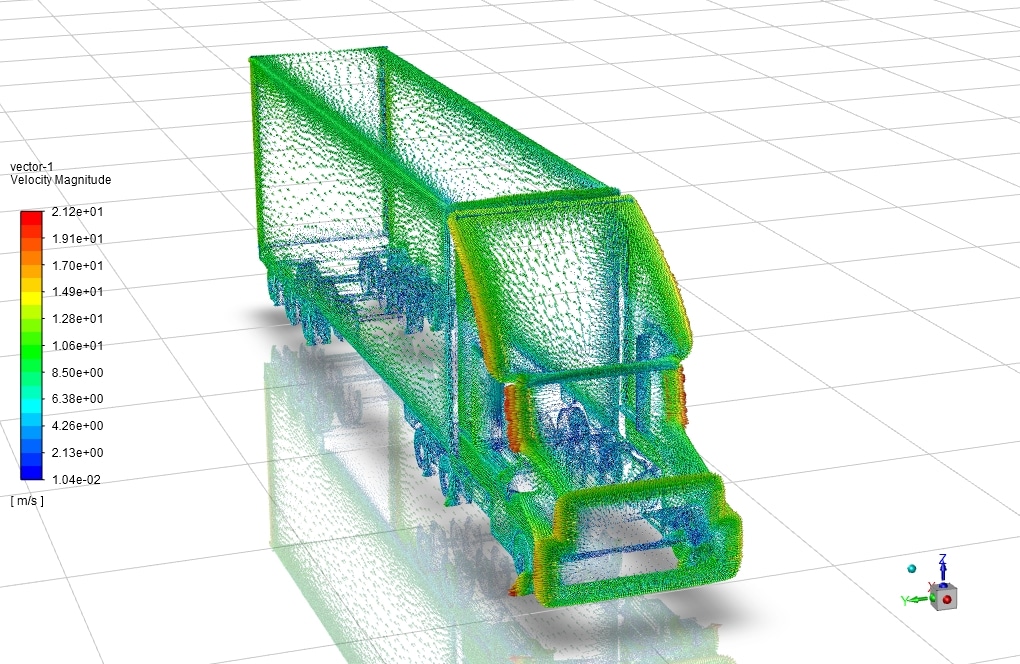
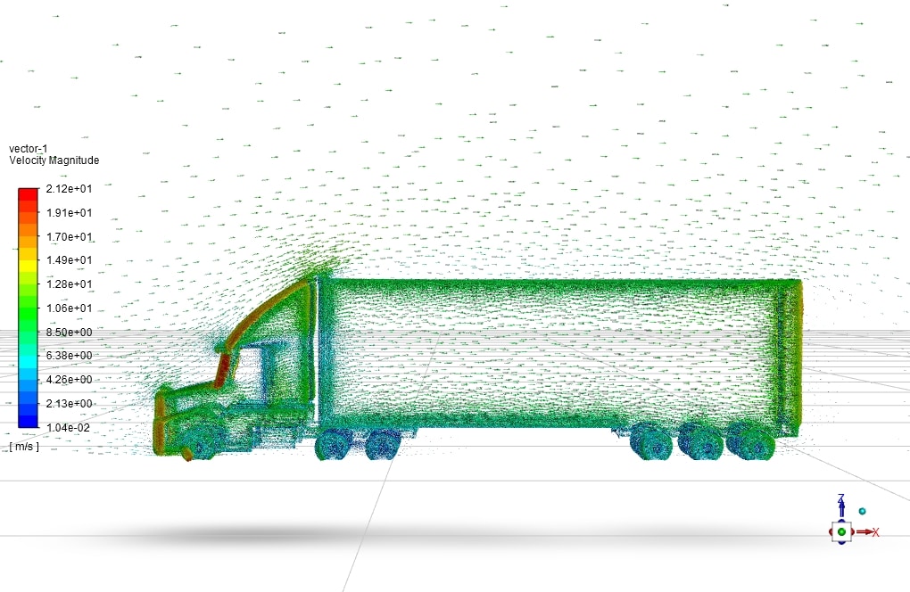
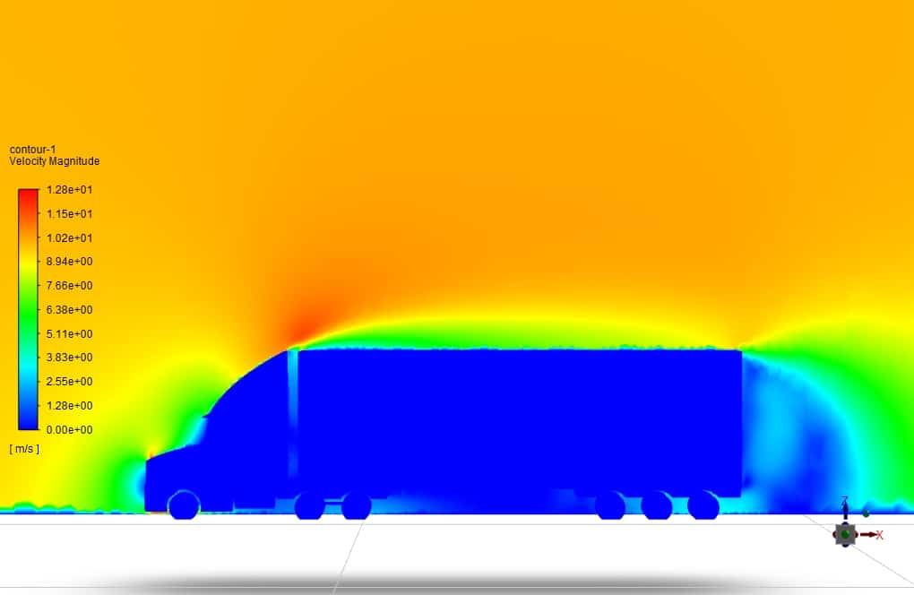
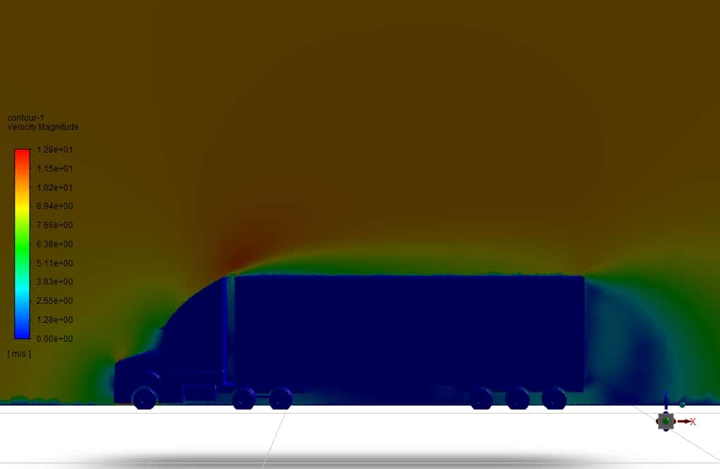
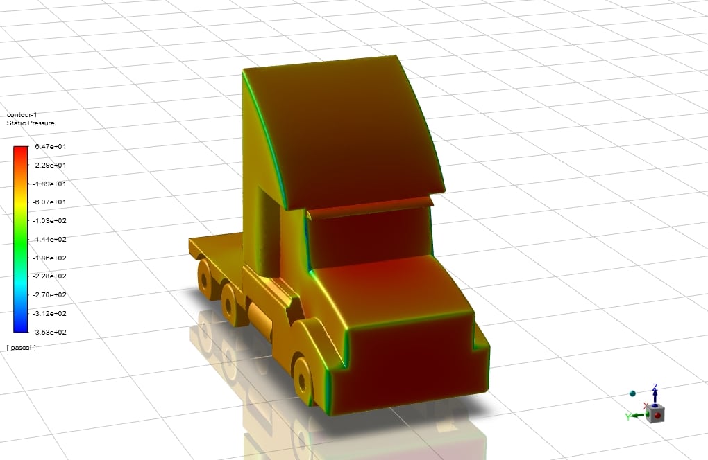
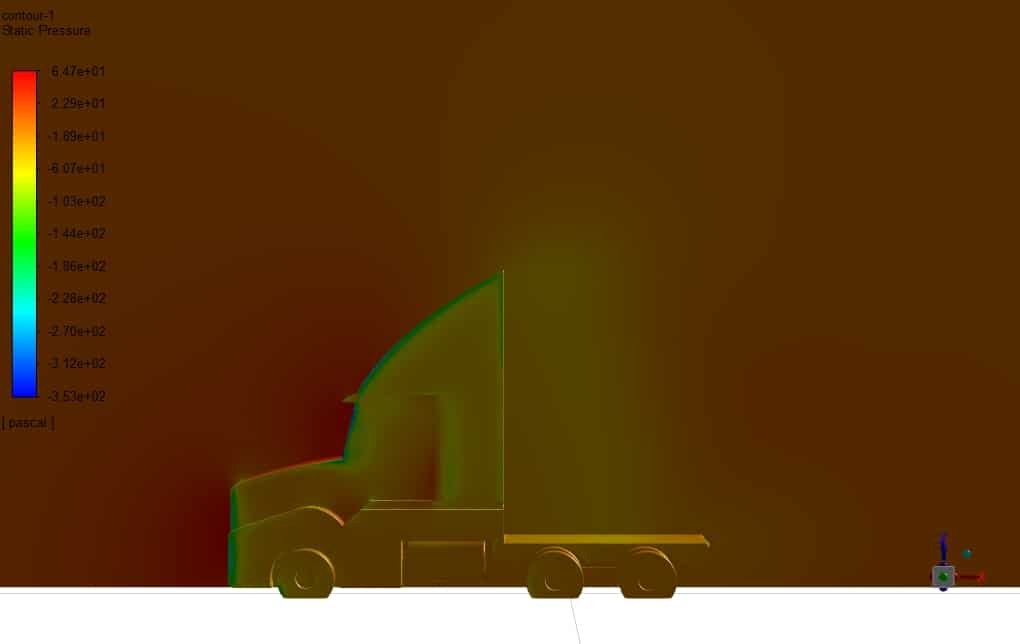
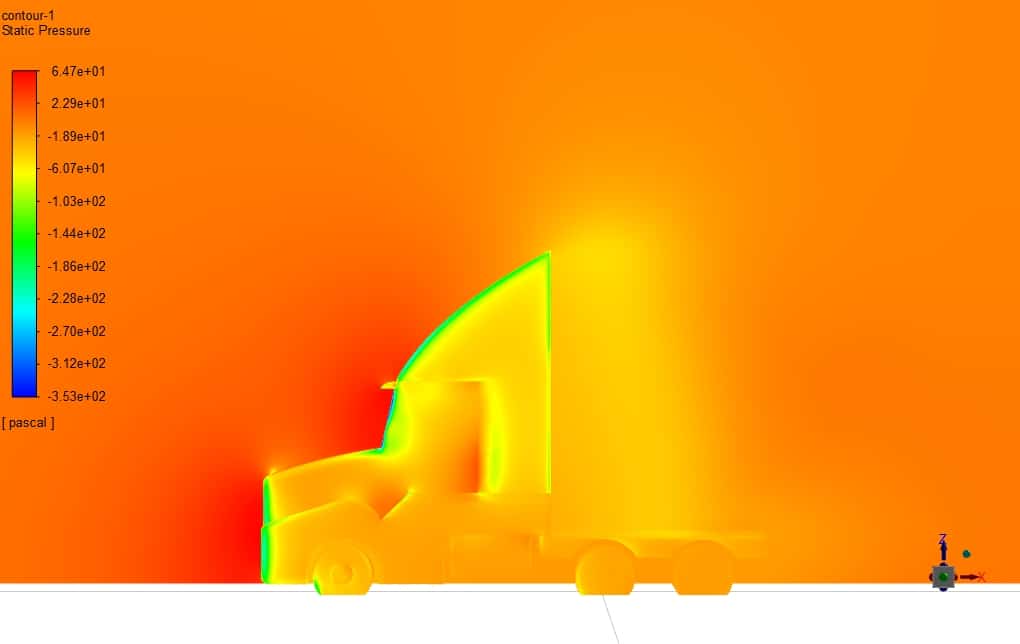
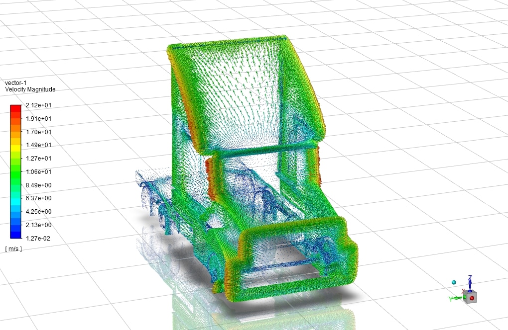
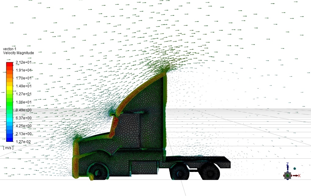
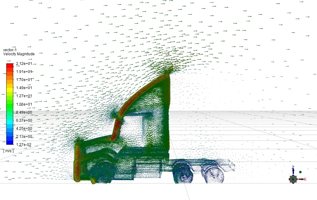
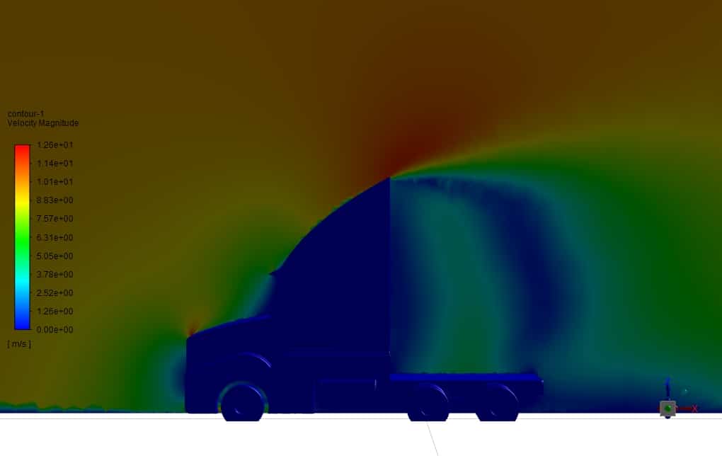
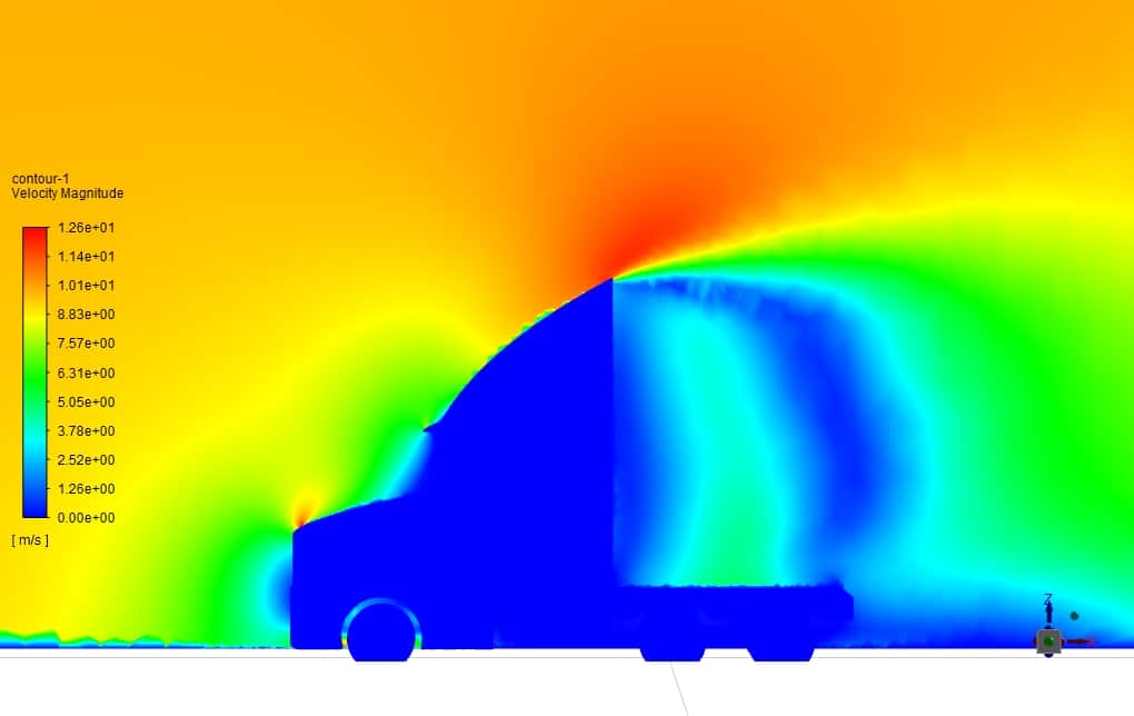
Descriptions of geometry, meshing, boundary conditions, fluid properties, Y-plus (Y+) criterion, and results are in order. In both modes, speed, pressure, and drag force will be examined, and we will introduce the best possible mode for drag reduction.
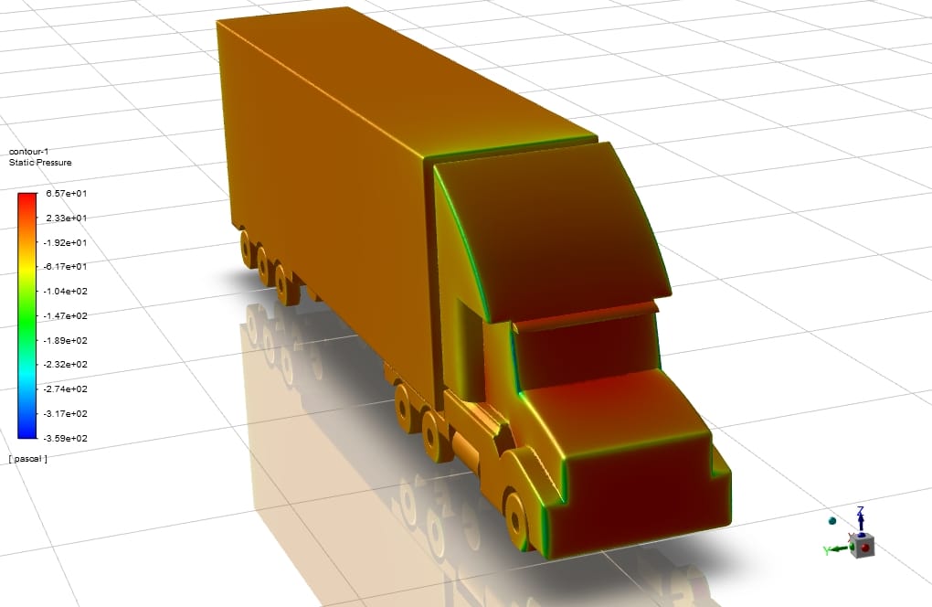
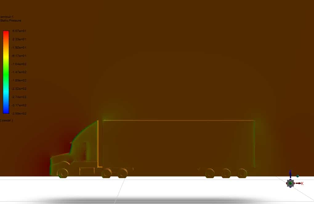
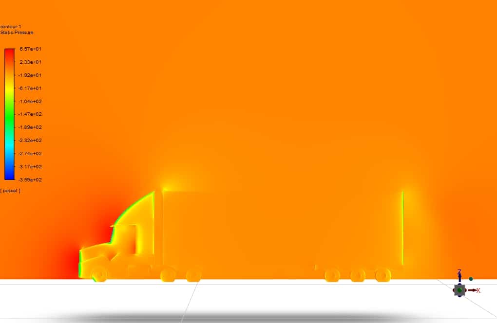
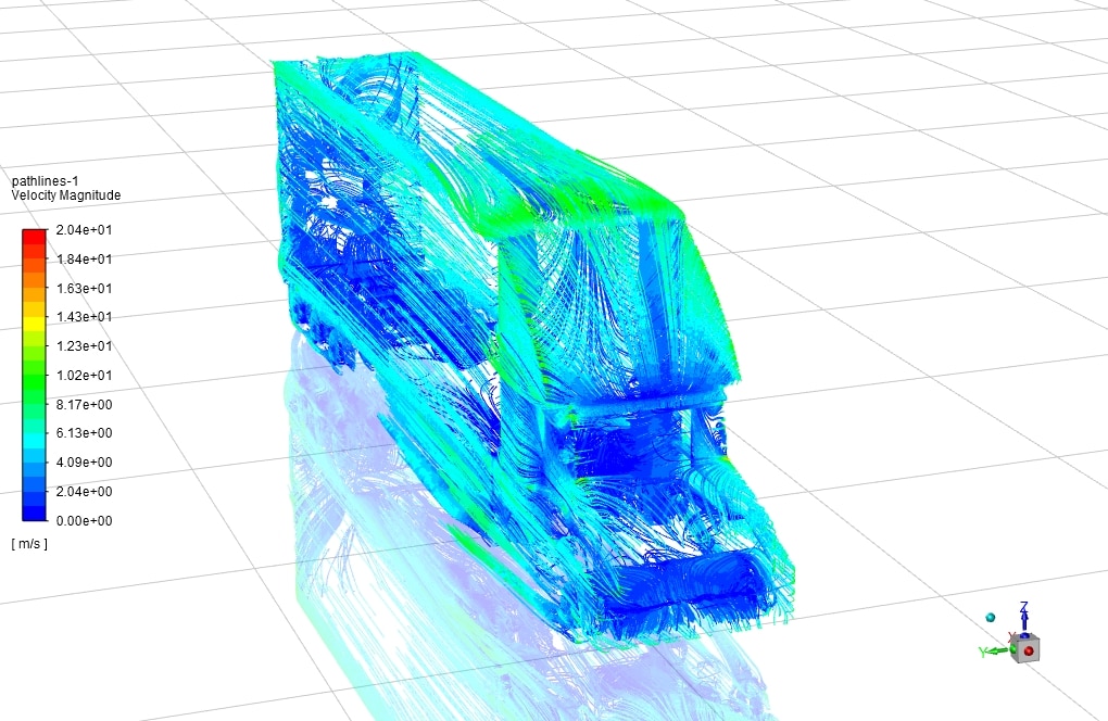
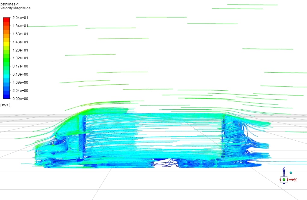
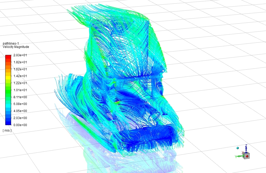
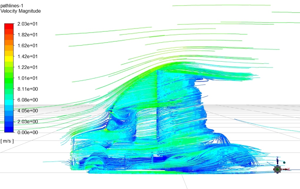
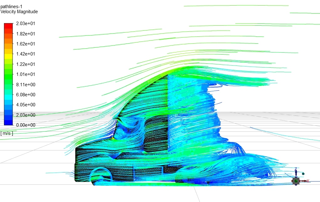
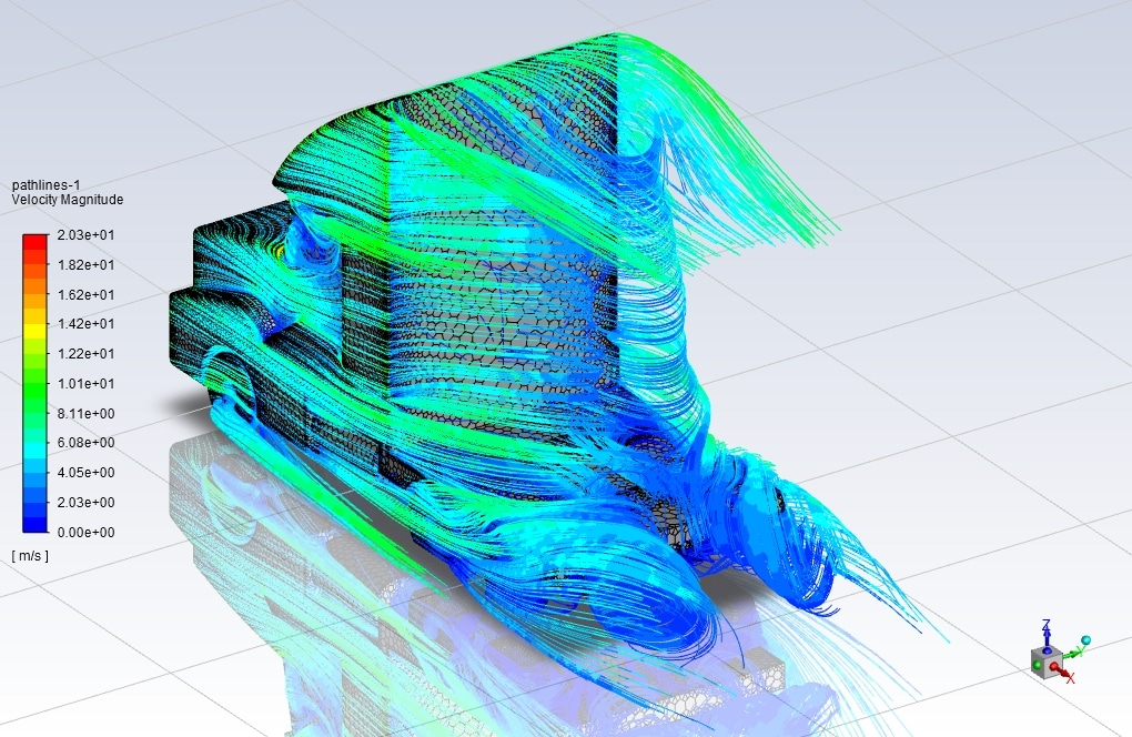
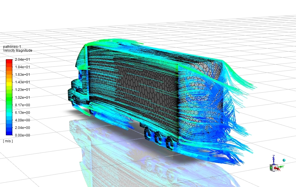
The results show that the drag force is less in the absence of the container than in the presence of it. This means that it is better to move the truck without the container. Of course, if the problem is done locally in the two parts of the back of the truck and the back of the container, the presence of the container will delay the separation of flow in the back of the truck.
On the other hand, the delay in separation causes the flow from the end of the container to cause less drag due to the smaller angle than the edge of the roof of the new truck. The images related to the flow lines in the back of the truck and behind the container show that the intensity of the vortices is effective from the angle of the top edge of the truck in the back of the truck in empty truck condition. This result can also be seen in the pressure coefficient diagram for comparing the two.

Miss Marcia Spencer DDS –
I am really amazed by the level of detail in the simulation of the truck’s aerodynamics, especially when considering the impact of a container. The fact that the aerodynamic impact of the truck with and without the container was taken into account to derive the drag force which influences fuel consumption and environmental aspects is both smart and crucial. Appreciate the thoughtful engineering and the comprehensive analysis provided by this training!
MR CFD Support –
Thank you for your positive feedback! We’re glad that you appreciated the intricate details of our CFD simulation for truck aerodynamics. It’s rewarding to see our efforts to deliver in-depth engineering analysis resonate well with our learners. If there’s more we can do to enhance your CFD learning experience, feel free to reach out to us!
Adeline Labadie –
I was totally impressed by the detailed investigation on the truck’s aerodynamics both with and without the container! It sounds like the simulation provided crucial insights for better fuel efficiency.
MR CFD Support –
Thank you so much for your positive feedback! We’re glad to hear you found our simulation on the aerodynamics of trucks insightful and impactful. If you ever need more information or additional CFD analyses, please don’t hesitate to reach out. Your satisfaction is our priority!
Prudence Leannon –
This course made the concept of truck aerodynamics crystal clear for me. The comparison between the truck with and without a container was particularly insightful. The focus on drag force and its implications on fuel consumption were very practical and useful from a design standpoint.
MR CFD Support –
Thank you for your review. We’re glad to hear that you found the course insightful and that it helped clarify the concepts of truck aerodynamics for you. Understanding drag force is crucial in vehicle design, especially to improve fuel efficiency. We appreciate you sharing your experience!
Caitlyn –
Hi. At the beginning of the tutorial, it was shown that the transient solver is selected, but at the run calculation tab, it was shown that a steady solver type is selected. Would you please explain that?
melika maysoori –
Hi, Caitlyn. Thank you very much for your attention. This is explained in the tutorial video because this product was originally supposed to be simulated in transient. This product is going to be modified and updated. However, you can do the simulation in transient. In the general section, select the transient mode instead of the steady mode, and then set the time step in the run calculation section. Let us know if you need more information. 😉
Jacob E. –
I didn’t understand how to convert 3D elements into polyhedral elements. Where is the convert tab?
melika maysoori –
Do not worry. I’m gonna explain u. :). To convert the entire domain of your mesh, use the Mesh / Polyhedra / Convert Domain menu. ( In fluent software). But note that conversion of a mesh to polyhedra only applies to 3D meshes that contain tetrahedral and/or wedge/prism cells. Hexahedral cells remain unchanged during conversion.
Timothy Roberts MD –
I was particularly impressed with the depth of analysis carried out in the Container Effect on Truck Aerodynamic CFD Simulation project! The methodology for investigating and comparing the drag force with and without a container was spot on. The use of the k-w SST turbulence model appeared to contribute significantly to the accuracy of your findings. It’s interesting to see how the presence of the container impacts flow separation. Great job on integrating theory with practical simulation!
MR CFD Support –
Thank you for your positive feedback! We are delighted to hear that the methodology and the turbulence model used in the Container Effect on Truck Aerodynamic CFD Simulation met your expectations and provided accurate and detailed insights. Understanding the aerodynamic performance of trucks is vital for improving fuel efficiency and reducing environmental impact. We appreciate your recognition of our efforts to effectively combine theoretical knowledge with practical application.
Prof. Lincoln Krajcik III –
Excellent CFD training material on container effect on truck aerodynamics using ANSYS Fluent. It’s fascinating to see how critical aerodynamic design is in reducing fuel consumption and environmental impact. The comparative analysis makes it vividly clear the difference a container can make — a truly practical insight for transport and automotive engineers.
MR CFD Support –
Thank you for your positive feedback. We’re delighted to hear that the Container Effect on Truck Aerodynamics CFD Simulation training material provided you with clear and practical insights. It’s our pleasure to support the transport and automotive engineering communities with top-notch CFD learning resources. If you have any more questions or need further assistance with CFD training, don’t hesitate to reach out!
Karli Hermiston –
This CFD course provided a great understanding of truck aerodynamics and the impact of container presence! It really clarified how economic and environmental constraints can guide design improvements.
MR CFD Support –
Thank you for your positive feedback! We are delighted to know that our CFD simulation course on truck aerodynamics has helped deepen your understanding of how design can influence economic and environmental factors. We appreciate you taking the time to complement our product.
Sydnee Tromp –
This course looks comprehensive! Does it include practical tips for optimizing truck design based on the CFD results obtained?
MR CFD Support –
The course distinctly provides a detailed analysis of the aerodynamic drag on a truck. It elucidates how different configurations and the presence of a container affect the truck’s aerodynamics. Through the lens of computational results, participants gain insights on design variations and learn to interpret the significance of drag forces, pressure distributions, and flow separation, creating a foundation to explore strategies for aerodynamic optimization.
Nels Baumbach II –
The CFD simulation tutorial for the truck aerodynamics influenced by a container was illuminating. I particularly appreciated how you contrasted the cases with and without a container to deduce the impact on drag force. The polyhedral mesh detail and the clear explanation of the simulation process using the k-w SST turbulence model improved my understanding significantly. Great work on illustrating the energy-saving benefits through aerodynamic design efficiency!
MR CFD Support –
Thank you for your positive feedback! We’re thrilled to hear that you found the tutorial on the impact of containers on truck aerodynamics insightful and that it contributed to your understanding of aerodynamic efficiency and energy savings in vehicle design. It’s always rewarding to know our products are making a difference. If you have further questions or topics you’re interested in exploring, don’t hesitate to reach out to us. Thanks again for choosing our training material!
Hope Skiles –
The CFD simulation is fantastic! The comparison made it very clear how much a container can affect aerodynamics. Outstanding work!
MR CFD Support –
Thank you for your positive feedback! We’re glad to know that the comparative analysis between a truck with and without a container was insightful for understanding aerodynamics’ impact on vehicle performance. Much appreciated!
Ms. Yadira Reichert PhD –
I’m thrilled with the detailed analysis provided for the truck with and without a container. It’s fascinating how the presence of the container affects airflow and drag force!
MR CFD Support –
Thank you for your positive feedback! We’re glad that you found the comprehensive analysis of the truck’s aerodynamics insightful. If you have further inquiries or require any additional information, please do not hesitate to ask.
Shawna Jakubowski –
The training helped me understand how the presence of a container affects aerodynamics, resulting in real-world applications for fuel savings. Excellent use of CFD methods to visualize and calculate drag reduction strategies.
MR CFD Support –
Thank you for your positive feedback! It’s fantastic to hear that our training product aided your comprehension of truck aerodynamics and the impact of container presence. We appreciate your recognition of our CFD methods and their practical benefits. If there’s anything else you’d like to learn about or any further assistance we can offer, please let us know!
Mr. Elliott Buckridge PhD –
This CFD course was a game-changer for understanding truck aerodynamics! Thanks so much!
MR CFD Support –
We’re delighted to hear that our CFD simulation course was immensely helpful to you. Understanding aerodynamics in truck design is crucial, and we’re glad our course made this complex topic clear. Thank you for your positive feedback!
Esta Stamm –
The learning material’s depth on truck aerodynamics and the drag force assessments thoroughly impressed me.
MR CFD Support –
We are incredibly glad to hear that our CFD simulation of truck aerodynamics provided valuable insights for you. Thank you for your positive feedback!
Raymond Rohan –
I found the Container Effect on Truck Aerodynamic CFD Simulation tutorial fascinating! The comparison between the truck with and without the container was very insightful. It really showcased how such simulations can lead to better fuel efficiency and environmental friendliness by analyzing the aerodynamic drag force. The details provided on the setup and outcome shown through pressure coefficient diagrams and flow lines were truly beneficial for understanding the impact of aerodynamics on large vehicles like trucks.
MR CFD Support –
Thank you for the wonderful feedback! We’re thrilled to hear that you found our tutorial on Container Effect on Truck Aerodynamic CFD Simulation both insightful and useful. Understanding aerodynamic principles is crucial for vehicle design, and we are glad our simulation could illuminate the significant effects on fuel efficiency and environmental impacts. We appreciate your kind words and hope that you will find our other tutorials just as beneficial.
Dr. Hermina Simonis Sr. –
I really appreciated how the Container Effect on Truck Aerodynamic CFD Simulation training was informative and comprehensive. The detailed steps and comparisons between the truck with and without the container provided great insight into how aerodynamics can impact fuel consumption and efficiency. The use of visuals like flow lines and the pressure coefficient diagram also helped in understanding the concepts better.
MR CFD Support –
We’re glad to hear that you found the Container Effect on Truck Aerodynamic CFD Simulation training to be comprehensive and helpful! Understanding the impact of aerodynamics on vehicles is crucial for improving efficiency, and we’re pleased that our visuals and explanations could aid your learning experience. Thank you for your positive feedback!
Mrs. Josefina Heathcote II –
Thank you for the excellent resources you provided for understanding truck aerodynamics. The comparison between configurations with and without the container was particularly insightful, and it was interesting to see how the presence of the container can influence drag and therefore fuel efficiency. The use of Solidworks for design and ANSYS Fluent for simulation seems like a robust approach.
MR CFD Support –
Thank you for your kind words and for recognizing the effort that went into creating this training resource. It’s our goal to provide comprehensive materials that help enable a deeper understanding of complex simulations like truck aerodynamics. If you have any further questions or need additional support, please don’t hesitate to reach out.
Dr. Yasmin Block –
This tutorial helped me understand the complete process for performing aerodynamic simulations of trucks. I particularly appreciate the comparison between conditions with and without the container. The visual results were very insightful. Great job!
MR CFD Support –
Thank you for your feedback! We’re glad that our tutorial was helpful and gave you clear insights into truck aerodynamics with container effects. We always strive to provide comprehensive and visually informative content. Your appreciation truly motivates us!
Erick Franecki –
The training on truck aerodynamics was fantastic! The clear comparison between scenarios with and without a container really helped me understand the implications on drag force and ultimately on the truck’s fuel efficiency. Excellent content and simulations for practical learning.
MR CFD Support –
Thank you for your kind words! We’re delighted to hear that you found our training on aerodynamics for trucks so valuable and that it effectively conveyed the critical concepts. Understanding the connection between drag force and fuel efficiency is indeed crucial for transportation design. Should you have any further questions or need more learning materials on similar topics, feel free to reach out!
Kennedy Hane –
I used this course for my graduate project, and the difference in drag reduction strategies with and without the container was eye-opening. The comparison between both conditions gave me a deep understanding of how the aerodynamics of a truck operates. I appreciate that the course also taught me how to use the k-w SST turbulence model. It’s been exceptionally helpful in my studies.
MR CFD Support –
We’re delighted to hear the course on Container Effect on Truck Aerodynamic CFD Simulation has been instrumental in your graduate project. It’s great to see you’ve gained valuable insights into the intricacies of truck aerodynamics and the application of the k-w SST turbulence model. Thank you for recognizing the value our training course has added to your educational pursuits. If you need further assistance or more resources, feel free to reach out to us anytime!
Montana Wiegand –
I was particularly impressed by how effectively the simulation dealt with the complex airflow problems around vehicles. It’s fascinating to see how the presence or absence of a container can have such a dramatic effect on drag forces. The synopsis of your work provides comprehensive insights which are imperative for enhancing fuel efficiency and reducing environmental impact.
MR CFD Support –
Thank you for your positive feedback! We are delighted to hear that you found the simulation insights valuable and that you appreciate the comprehensive analysis of the drag forces with and without the presence of a container. Our goal is to provide detailed and useful CFD simulation studies to assist in improving vehicle design for better aerodynamics. We’re glad that the results of our work can contribute to advancements in fuel efficiency and a reduced environmental impact. Thank you for recognizing the effort we put into our training materials.
Alaina D’Amore –
The training was detailed and well-organized, guiding me effectively through each simulation step. Visualizing aerodynamic forces with and without the container through CFD modeling helped me understand the significant influence of design on drag and fuel efficiency. Truly impressive application of ANSYS Fluent!
MR CFD Support –
We’re thrilled to read that you found our Container Effect on Truck Aerodynamic CFD Simulation training valuable and informative! Your grasp of the concepts tells us that the course materials are doing their job. Thank you for recognizing the effort that goes into our training. If there are any additional concepts or tools you’re interested in exploring, do let us know!
Joaquin Langosh I –
This CFD training on the effect of a container on truck aerodynamics helped me grasp the crucial aspects of drag force. My fuel consumption calculations for my fleet have become more accurate thanks to the insights provided. Excellent material for practical applications!
MR CFD Support –
We’re thrilled to hear that you found the Container Effect on Truck Aerodynamics CFD Simulation training useful and that it has made a positive impact on your fuel consumption estimates. Thank you for your kind words and for taking the time to share your experience with us!
Miss Ramona Price III –
I found the section mentioning Y-plus (Y+) criterion intriguing. Could you give a bit more details on how the Y-plus values were ensured to be within an acceptable range to provide accurate results for the boundary layer?
MR CFD Support –
In this simulation, achieving a suitable Y-plus value was critical for accurately capturing the boundary layer characteristics, which directly influence the aerodynamic forces. As is standard for CFD simulations, the mesh was refined near the truck’s surface to reduce the Y-plus value and ensure that it falls within the appropriate range for the chosen turbulence model. In this case, the k-w SST turbulence model typically requires a Y-plus value close to 1 to accurately resolve the boundary layer without the need for wall functions.
Ms. Rosalind Lindgren MD –
I’m thrilled with the level of detail in this simulation. Noticed substantial differences in fuel efficiency based on the presence of the container. Excellent project for understanding practical aerodynamics!
MR CFD Support –
Thank you for your positive feedback! We’re glad to hear that our training on truck aerodynamics and the container’s drag impact helped provide valuable insights into the truck’s design and fuel efficiency. We continually strive to provide detailed and practical simulations.