Stall Investigation Over a Wing, ANSYS Fluent CFD Simulation Training
$220.00 Student Discount
- The problem numerically simulates the Stall phenomenon over a Wing using ANSYS Fluent software.
- We design the 3-D model by the Design Modeler software.
- We Mesh the model by ANSYS Meshing software.
- The air is assumed to be incompressible.
Click on Add To Cart and obtain the Geometry file, Mesh file, and a Comprehensive ANSYS Fluent Training Video.
To Order Your Project or benefit from a CFD consultation, contact our experts via email ([email protected]), online support tab, or WhatsApp at +44 7443 197273.
There are some Free Products to check our service quality.
If you want the training video in another language instead of English, ask it via [email protected] after you buy the product.
Description
Description
This project investigates the stall phenomenon over a wing using CFD simulation in ANSYS Fluent software. We perform this CFD project and investigate it by CFD analysis.
An airfoil is a streamlined shape capable of generating significantly more lift than its drag. Subsonic flight airfoils have a characteristic shape with a rounded leading edge, followed by a sharp trailing edge, often with a symmetric curvature of upper and lower surfaces.
The present model is designed in three dimensions using the Design Modeler software. This geometry is meshed in Ansys meshing software.
Stall Methodology
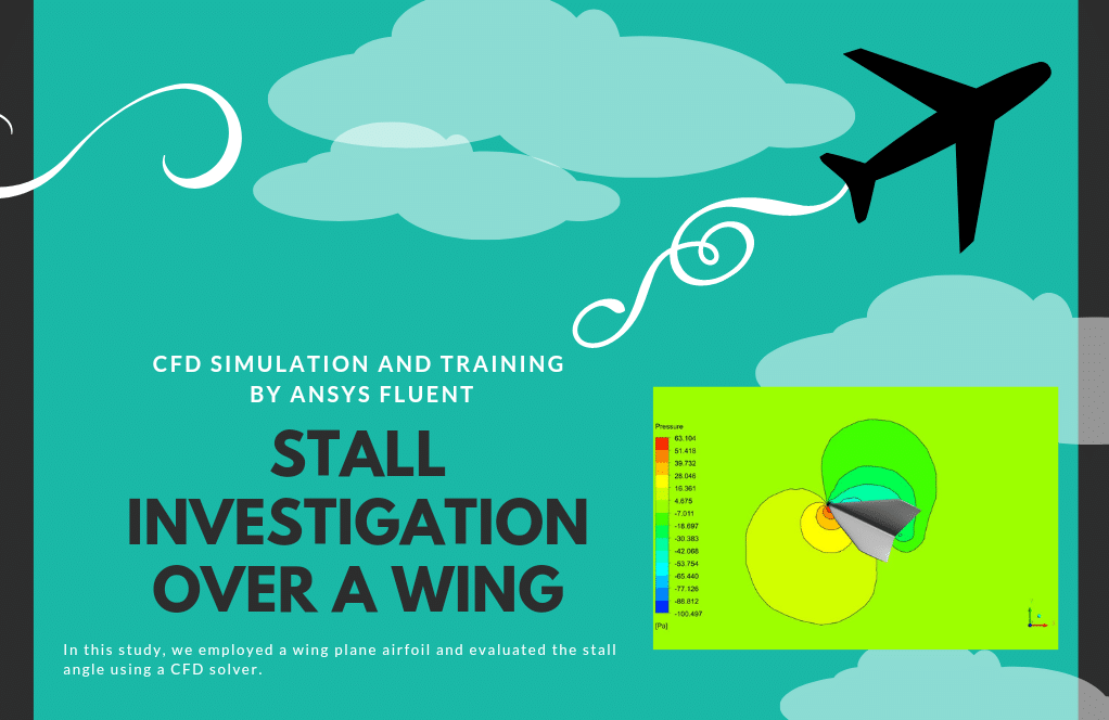
We employed a wing plane airfoil in this study and evaluated the stall angle using a CFD solver.
Also, the air is assumed to be incompressible and isothermal. The geometry is a 3-meter airfoil inside a 60-meter wind tunnel. Also, the maximum speed of 10 m/s is selected for the inlet.
Moreover, the SST k-omega model has been used to solve fluid equations due to its advantage in predicting flow patterns near and far from the surfaces.
Stall Conclusion
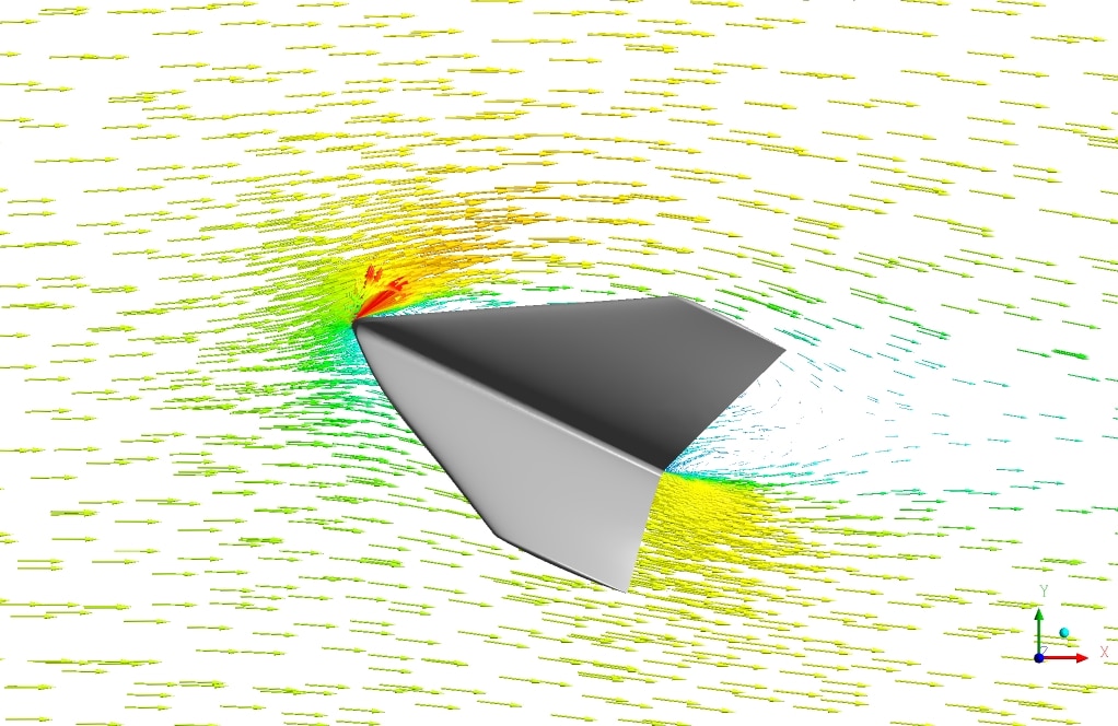
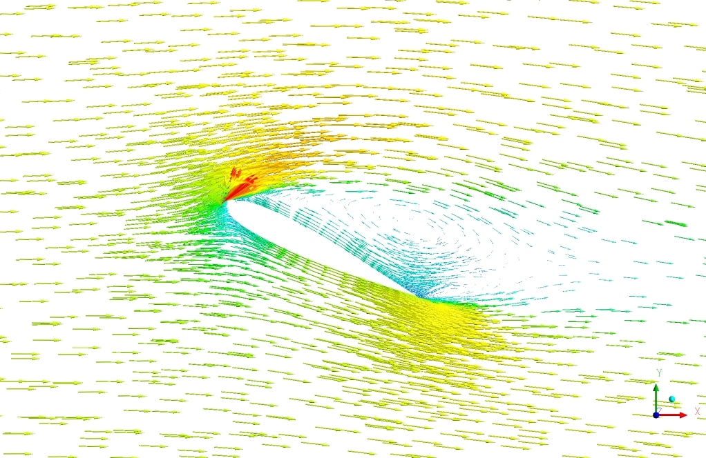
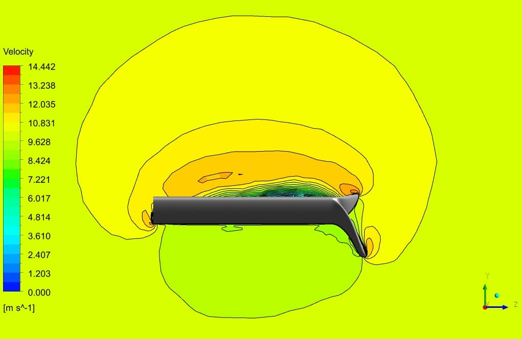
At the end of the solution process, we obtain two- and three-dimensional contours related to pressure, velocity, streamlines, and velocity vectors.
Furthermore, the maximum velocity value was found at the top surface of the airfoil, while the maximum pressure value was at the leading edge, where the velocity was minimum.
Additionally, the streamlines illustrate the quality of the flow streams resolved in the wake section, which is the core challenge of aerodynamic simulation and brings insight into the problem.
We rotated our current airfoil by the angle of 5 from zero to 45 degrees to identify the stall angle. By doing so, the drag and lift values were increased until the angle of 22.5 degrees, when the lift value started to decrease. The noted was found to be the stall angle and corresponded to the maximum lift value.




Robert Goldner –
After going through the Stall Investigation CFD Simulation training for ANSYS Fluent, I have to applaud the thorough approach taken. The session on determining the stall angle provided real clarity, and the use of various flow models, like SST k-omega, to successfully predict the aerodynamics around the airfoil was impressive. I also appreciated the inclusion of high-resolution contour mappings which were key to understanding complex flow behaviors around the stall angle.
MR CFD Support –
Thank you for your positive feedback on the Stall Investigation training. We’re delighted to hear that the training was informative and beneficial, especially concerning the demonstration of stall phenomenon and the prediction of aerodynamic characteristics. Your appreciation for the detailed visualization and application of the SST k-omega model reinforce the value of our training content. We take pride in providing comprehensive learning experiences and are thrilled when they meet our clients’ expectations. Thank you once again for choosing our training.
Prof. Jefferey Ryan II –
I was impressed with the clear explanation of the wing stall phenomenon using the SST k-omega model in ANSYS Fluent. It sounds like this CFD project effectively captured the essential forces on the airfoil during the stall and pre-stall circumstances. Great job incorporating the gradual rotation technique to determine the stall angle precisely.
MR CFD Support –
Thank you for taking the time to write such an encouraging review! We are thrilled to hear that you found the explanation of the wing stall phenomenon and the use of the SST k-omega model to be clear and informative. We take pride in our methodology for capturing critical aerodynamic forces and are glad that the gradual rotation technique effectively showcased the stall angle. Your satisfaction with our training resource is very gratifying for our team. We look forward to providing you with more comprehensive and easy-to-understand simulations.
Leola Bayer –
Stall investigation is critical for aircraft design. Did this simulation help in understanding how the wing design affects stall characteristics?
MR CFD Support –
Absolutely! This simulation effectively demonstrated the stall phenomenon. By incrementally rotating the airfoil and observing changes in lift and drag, we were able to pinpoint the exact stall angle. This is valuable for optimizing wing design for better stall characteristics and overall aircraft performance.
Josue Feest –
The provided training truly enhanced my understanding of aerodynamics and the stall phenomenon. The detailed results and methodology allowed me to grasp complex concepts with clarity. Great resource for anyone interested in CFD applications for aerospace!
MR CFD Support –
Thank you for your positive feedback. We’re delighted that our training helped you deepen your understanding of aerodynamics and stall phenomena. It is our goal to offer a clear and detailed learning experience for all our users. We appreciate your recognition of our work!
Rudy Hettinger –
Wonderful. The colored streamlines presented in the results are so insightful, showing precisely how the flow separates at the point of stall. It’s quite fascinating to see the aerodynamics at play!
MR CFD Support –
We’re thrilled to hear that you found the simulation results insightful! Witnessing the flow separation and the stall occurrence helps in understanding the complex aerodynamics of wings. Thank you for your positive feedback, and we’re glad that our training material met your expectations.
Caterina Schulist –
I was really impressed by the level of detail in the stall investigation study for the airfoil. The practical approach of incrementing the angle of attack to find the stall angle provided clear insights. Generated visuals like the streamlines must have been extremely helpful in understanding the flow. Kudos to the team for utilizing the SST k-omega model effectively!
MR CFD Support –
Thank you for the positive feedback! We are thrilled to hear that the details and approach used in the stall investigation have met your expectations. It’s great to know the visuals and choice of SST k-omega were helpful. Your acknowledgment motivates us to keep delivering high-quality CFD analysis.
Miss Bulah Wilkinson Sr. –
I’m truly astonished by the detail in the Stall Investigation Over a Wing simulation training. It’s clear that a significant amount of work and intricate analysis went into this study to bring about such comprehensive findings, from understanding the aerodynamics to pinpointing the precise stall angle. Excellent work on conveying complex concepts with clarity and precision!
MR CFD Support –
Thank you for your kind words! We’re delighted to hear that our ANSYS Fluent CFD Simulation Training for Stall Investigation Over a Wing met your expectations. Providing in-depth analysis and clear understanding of complex aerodynamic phenomena is a priority for us, and it’s great to know that you found the training comprehensive and insightful. Your feedback is highly appreciated!
Diana Terry I –
The CFD analysis you presented for assessing stall behaviour on an airfoil in ANSYS Fluent sounds like a valuable learning tool to understand aerodynamics better. Having the airfoil angles incrementally adjusted and the resulting forces and flow characteristics recorded must offer insightful data on the stall phenomenon. Do you cover both 2D and 3D simulations for this phenomenon?
MR CFD Support –
Yes, indeed, our training and analysis include both 2D and 3D simulations to provide a comprehensive understanding and visual demonstration of the stall phenomenon over the wing. Such an approach allows students and professionals to closely observe the transition from attached flow to the separation that occurs during the stall condition.
Ms. Reyna Jaskolski MD –
The tutorial on stall investigation over a wing was instrumental for my aeronautics project. The detailed examination of flow patterns using the SST k-omega model provided clarity on behavior at various angles. The visualization of stall phenomena gave me great insight, enhancing my comprehension of aerodynamic principles.
MR CFD Support –
Thank you for your kind words! We’re elated to hear that our CFD simulation training on stall investigation proved to be beneficial for your project and helped you gain a better understanding of aerodynamics. It’s our goal to provide clear and informative tutorials for our users.
Dee Paucek –
I’m having trouble understanding the stalling of the wing. Could you please explain what causes stall and how it’s represented in the CFD simulation results?
MR CFD Support –
Stalling occurs when the airflow over the wing separates due to an excessive angle of attack, which then causes a rapid decrease in lift. In the CFD simulation, the point of stall is represented graphically by the sudden drop in lift force on the plotted lift graph against the angle of attack and can be visually confirmed by increased flow separation and turbulent wake regions in the flow field results, such as streamlines, pressure, and velocity contours.
Kraig Fahey –
In this review the static pressure contour and also drag and lift coefficients around the wing will say you everything about the flow regime.You will visually understand everything even if you are a beginner.
MR CFD Support –
Thank you for your kind review! We’re pleased to hear that the static pressure contours and the drag and lift coefficient results were clear and insightful, even for those who might be new to CFD simulations. Your feedback is valuable to us, and knowing that our material aids in understanding complex flow regimes is incredibly rewarding. We strive to provide comprehensive and user-friendly learning resources.
Angus Emard –
I’m genuinely impressed with the way this training elucidates the stall phenomenon through practical, hands-on CFD analysis. The step-by-step presentation of the airfoil’s behavior at various angles until reaching stall offers an intuitive learning curve. Thrilled to see complex aerodynamics made so accessible!
MR CFD Support –
Thank you for your positive feedback! We’re thrilled to hear that our training on stall investigation over a wing has made the complex principles of aerodynamics accessible and easy to understand. Your appreciation motivates us to continue providing high-quality educational materials. If you have any further questions, don’t hesitate to ask.