Acoustic in a Turbojet Intake Fan CFD Simulation
$200.00 Student Discount
- The problem numerically simulates Acoustic in a Turbojet (Intake Fan) using ANSYS Fluent software.
- We design the 3-D model with the Design Modeler software.
- We Mesh the model with ANSYS Meshing software, and the element number equals 3723166.
- We use the Density-based solver to consider compressible flow.
- We use the Frame Motion (MRF) to define the rotational movement.
- We use the Broadband Noise Sources model to define the Acoustic model.
To Order Your Project or benefit from a CFD consultation, contact our experts via email ([email protected]), online support tab, or WhatsApp at +44 7443 197273.
There are some Free Products to check our service quality.
If you want the training video in another language instead of English, ask it via [email protected] after you buy the product.
Description
Acoustic CFD Simulation in a Turbojet (Intake Fan), ANSYS Fluent Training
The present problem simulates the airflow inside a turbojet and examines the acoustic wave and the sound produced inside this turbojet by ANSYS Fluent software. The software uses the acoustic model to study sound or acoustic waves.
Also, the pressure and temperature of the airflow are 85416.92 pascals and 283.9524 K, respectively, obtained according to the related equations.
Turbojet Methodology
The model includes a turbojet that has a fan in its inlet. This fan rotates at 2000 rpm and around the X-axis in the current model. Therefore, an airflow area is defined around the fan, modeled using frame motion (MRF).
This turbojet is moving in the air with a Mach number of 0.5, which indicates that the flow can be considered compressible; Because the value of the Mach number is more than 0.3. Mach number is equal to the ratio of the object’s velocity in the fluid to the velocity of sound in the same fluid.
Therefore, a density-based solver is used in this model, and the density is defined as the ideal gas for the airflow in the material section. In the present simulation, the defined airflow around the turbojet has a pressure far-field boundary condition of Mach number of 0.5.
The Broadband Noise Sources model is also used to define the acoustic model. Definitive density is equivalent to air density, i.e., 1.225 kg/m3; sound speed is equivalent to sound speed in the air, i.e., 340 m/s and reference acoustic power is equal to 1e-12.
The current model is designed in three dimensions using Design Modeler software. The model consists of two parts, which include the body of a turbojet with a fan inside it, which is located inside a computational domain for airflow in the form of a cylinder.
The area around the fan is defined as an independent computational area so that the area under rotation of the fluid due to the fan rotation can be defined using the frame motion method.
Also, the entire defined cylindrical space around the turbojet body is defined as a pressure far-field boundary condition. The meshing is done in three dimensions using the ANSYS Meshing software. The mesh type is unstructured, and the element number is 3723166.
Turbojet Conclusion
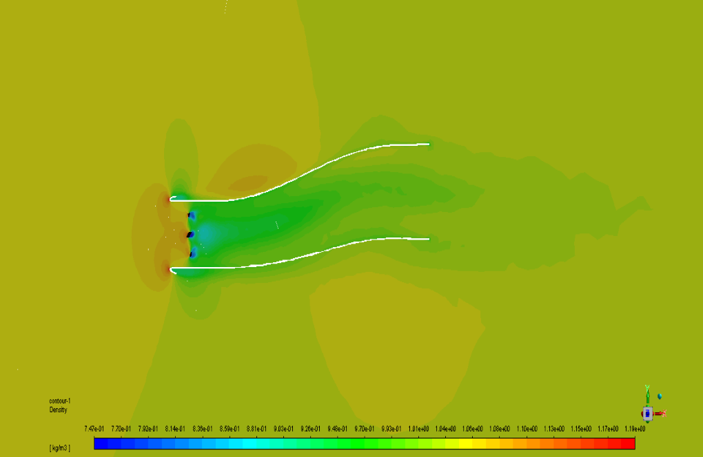
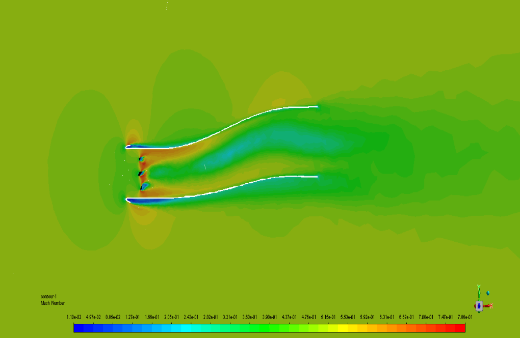
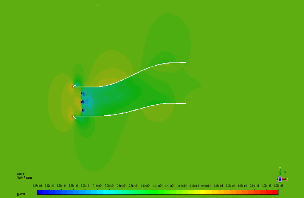
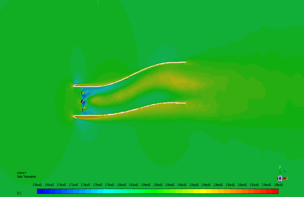
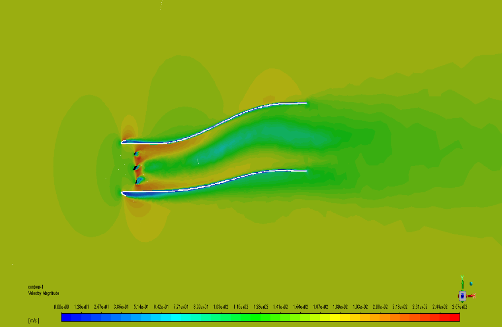
For the current simulation, we present the contour and vector of velocity, pressure, temperature, Acoustic Power Level(dB), and Surface Acoustic Power Level(dB) of the Domain to give much insight into the problem.
Briefly, as the air hits the fan and fan wall, the acoustic parameters of the solution are visible more precisely behind it. Also, the amount of Surface Acoustic Power Level(dB) can be seen on the fan surface as the noise resource.
In conclusion, the plots of Acoustic Power Level(dB) and Surface Acoustic Power Level(dB) through the centerline are achieved, which helps more to understand the exact amount of acoustic parameters behind the fan.

Stephon Abernathy –
The CFD simulation details provided in this product really impressed me. The use of the Broadband Noise Sources model for analyzing the acoustics within a turbojet is insightful. It seems as though a lot of care was put into setting up realistic boundary conditions and looking into the impact of the rotating fan on the acoustics. The choice of solver and meshing strategy also points to a rigorous method that aims to accurately capture the relevant physics of the problem. I’m particularly curious about the dB contours which seem like they’d offer a clear view of the sound distribution and intensities within the turbojet model.
MR CFD Support –
Thank you for your positive feedback. We’re delighted to hear that you appreciate the meticulous attention to detail in our simulation setup for the turbojet intake fan CFD analysis. Accurate acoustic simulation requires careful consideration of many factors, and our use of the appropriate models and boundary conditions is crucial in providing a realistic and informative understanding of the system’s acoustics. The dB contours indeed provide a detailed account of the acoustic power levels and their distribution, which is essential for sound analysis and mitigation in practical applications. Your insight and engagement with the details of our product are much appreciated!
Kane D’Amore –
What an insightful simulation! I’m impressed by how the interaction between the airflow and turbojet fan, along with the corresponding acoustic effects, was explored.
MR CFD Support –
Thank you for your positive feedback. We are glad to know that our simulation met your expectations and provided the thorough insight you were looking for!
Tracey Hegmann –
I’m amazed by the detailed analysis of the acoustic modeling in the turbojet intake fan simulation! I now have a much clearer understanding of how noise is generated and how it propagates in such a system.
MR CFD Support –
Thank you so much for your positive feedback! We’re incredibly pleased that our simulation and analysis on acoustic modeling could provide you with clear insights into the noise generation within a turbojet intake fan. Your understanding and satisfaction with the training material is our top priority. If you ever have more questions or need further clarification on any aspect, please feel free to reach out to us!
Jalyn Feest –
Absolutely fascinating results! The insight offered into the sound/pressure relationships within a turbojet environment is exceptionally detailed. Kudos to the team for such a comprehensive study, highlighting the interaction of airflow dynamics and acoustics.
MR CFD Support –
Thank you! We’re delighted to hear you found the acoustic simulation insights enlightening and appreciate the detailed feedback. Our team is committed to providing comprehensive and practical CFD insights. Your encouragement motivates us to continue delivering high-quality simulations and studies.
Angeline Cremin –
This Acoustic CFD Simulation for the turbojet intake fan seems quite insightful. Is the simulation capable of predicting noise levels that would be comparable to actual aircraft standards, and how can we use this data to improve aircraft design?
MR CFD Support –
The simulation uses advanced acoustic models in ANSYS Fluent, which can indeed predict noise levels that approximate actual real-world scenarios. The data obtained from acoustic parameters such as Acoustic Power Level(dB) and Surface Acoustic Power Level(dB) facilitates the assessment against aircraft noise standards. Designers can utilize this information to pinpoint areas of high noise generation and revise the intake fan’s geometry or materials compositions to ameliorate noise, ultimately enhancing aircraft design concerning acoustic performance.
Robin Bailey –
The detailed contour presentations are incredible! The insights into noise production in the turbojet are crucial for design optimization. Great to see accurate simulations coupling airflow with acoustics in such a complex system.
MR CFD Support –
Thank you for your positive feedback! We are thrilled to hear that the acoustic CFD simulation for the turbojet intake fan provided you with valuable insights. Our goal is to deliver precise and comprehensive simulations to help with design optimization. We appreciate your recognition of our efforts!