Cooling of Airfoil Surface by Lateral Hole Air Inlets
$80.00 Student Discount
- The problem numerically simulates Cooling of Airfoil Surface by Lateral Hole Air Inlets using ANSYS Fluent software.
- We design the 3-D model by the Design Modeler software.
- We Mesh the model by ANSYS Meshing software, and the element number equals 582263.
- The Energy Equation is activated to define the cooling process.
Click on Add To Cart and obtain the Geometry file, Mesh file, and a Comprehensive ANSYS Fluent Training Video.
To Order Your Project or benefit from a CFD consultation, contact our experts via email ([email protected]), online support tab, or WhatsApp at +44 7443 197273.
There are some Free Products to check our service quality.
If you want the training video in another language instead of English, ask it via [email protected] after you buy the product.
Description
Cooling of Airfoil Surface by Lateral Hole Air Inlets, ANSYS Fluent Tutorial
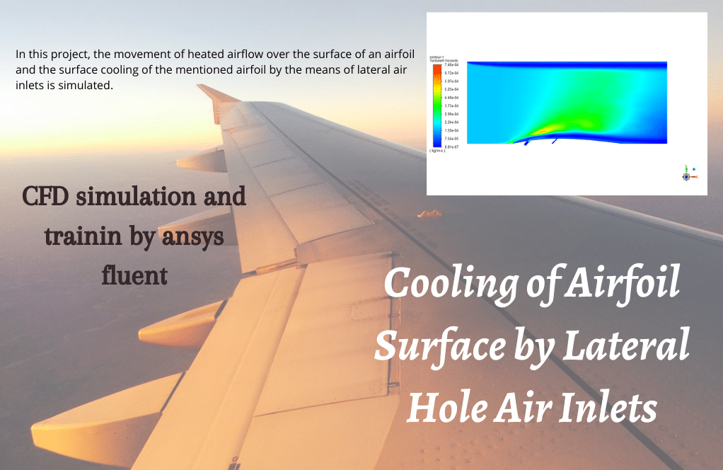
The present problem simulates the movement of heated airflow over the surface of an airfoil and the surface cooling of the mentioned airfoil using lateral air inlets using ANSYS Fluent software. We perform this CFD project and investigate it by CFD analysis.
In the field of jet engines, surface cooling of airfoils has become one of the most important issues in mechanical engineering and aerospace.
The present model is designed in three dimensions using Design Modeler software. The meshing of this present model has been generated by Ansys Meshing software. The total cell number is 582263.
Cooling Methodology
In this project, the movement of heated airflow over the surface of an airfoil and the surface cooling of the mentioned airfoil using lateral hole air inlets is simulated by ANSYS Fluent software.
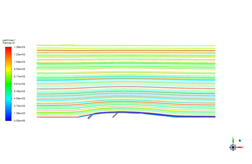
The heated air enters the computational domain with a velocity and temperature of 15 m/s in the X direction and 600 K, respectively. Two lateral air inlets are responsible for the surface cooling of the blade or airfoil.
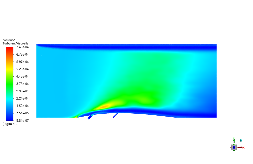
The air also enters through these cooling inlets with a velocity and temperature of 6.59 m/s and 300 K. Standard k-epsilon model is exploited to solve turbulent flow equations, and the Energy equation is activated to calculate the temperature distribution inside the computational domain.
Cooling Conclusion
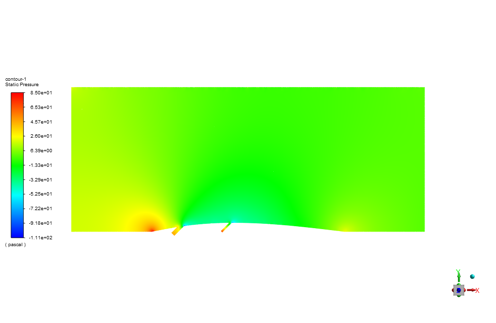
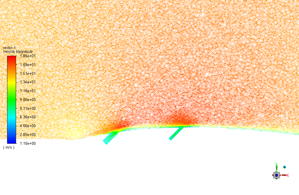
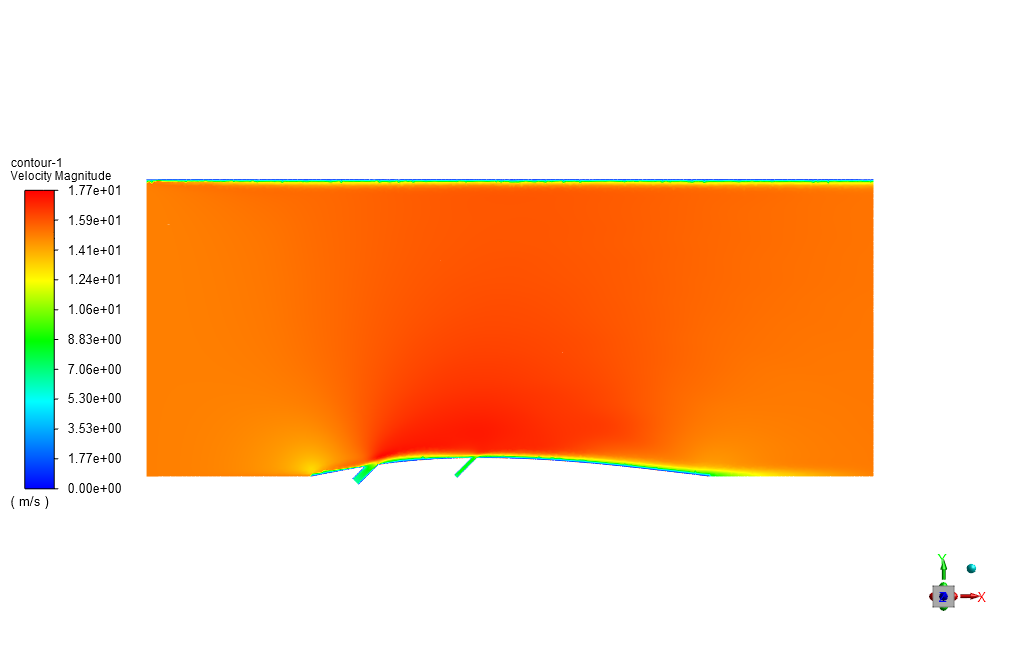
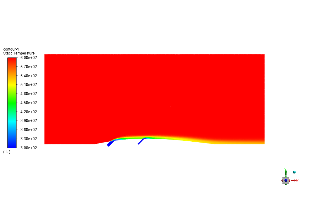
At the end of the solution process, we obtain two-dimensional contours related to pressure, velocity, and temperature. For instance, the temperature reduction near the airfoil’s surface is evident due to the injection of cold airflow.
Furthermore, it can be observed in temperature contour and changes of blade temperature in terms of blade position diagram that the lateral inlets have effectively done their job and lowered the temperature of the blade’s surface, as the free stream has a temperature of 600 K and the blade’s final temperature is less than 520 K.


Javonte Heaney –
Fantastic! I observed a clear difference in temperature on the airfoil due to the lateral cooling inlets. It showed how cooling effectiveness can be enhanced even under high heated airflow conditions. This simulation could be vital for improving the longevity of jet engine components.
MR CFD Support –
Thank you for your kind words! We’re truly glad to hear that you’ve recognized the importance of the simulation results and found them applicable to real-world scenarios in jet engine cooling. Your satisfaction with the effectiveness demonstrated in the tutorial is very motivating for our team. If you have any more feedback or need further assistance, feel free to reach out!
Prof. Elnora Rath MD –
This tutorial was incredibly insightful for my project on jet engine airfoil cooling. The step-by-step explanation of setting up the simulation in ANSYS Fluent made the learning curve much easier. The temperature distributions and the effectiveness of the cooling inlets came out just like how you described. I am thoroughly impressed with how well the concepts were explained and made practical.
MR CFD Support –
Thank you for your fantastic review! We’re thrilled to hear that our tutorial aided your project on jet engine airfoil cooling and made the learning process smoother. It’s our pleasure to provide comprehensive and practical learning material. Should you have any further queries or need more assistance with ANSYS Fluent, feel free to ask. Good luck with the rest of your project!
Harvey Vandervort –
This tutorial was very informative and practical for understanding airfoil surface cooling strategies. The explanation of the methodology, particularly how the lateral inlets contribute to the cooling process, was clear and easy to follow.
MR CFD Support –
Thank you for your kind words! We’re glad you found the tutorial on ‘Cooling of Airfoil Surface by Lateral Hole Air Inlets’ informative and easy to understand. Your feedback is greatly appreciated, and we’re pleased to know that our explanations helped you comprehend the cooling strategies for airfoils.
Prof. Mia Littel –
The tutorial was very informative, and the visualization of temperature reduction on the airfoil surface was particularly impressive. The use of lateral hole air inlets seems like an efficient cooling strategy, and the detailed results helped me understand the impact of secondary cooling on the overall temperature distribution.
MR CFD Support –
Thank you for your positive feedback! We’re glad you found the tutorial informative and could clearly see the benefits of lateral hole air inlets for airfoil cooling. If you have any further questions or need more information, feel free to reach out. We’re here to help!
Ronaldo Fadel –
I’ve recently used your Cooling of Airfoil Surface by Lateral Hole Air Inlets tutorial and it was incredibly helpful! I now better understand the cooling process of airfoil applications within aerospace engineering. The step-by-step guide provided clear instructions, and I could visually significant temperature changes on the airfoil surface. This high-quality tutorial is perfect for getting hands-on experience.
MR CFD Support –
We are thrilled to hear that our tutorial on the Cooling of Airfoil Surface by Lateral Hole Air Inlets was helpful and insightful for you! It’s great to know that the step-by-step instructions and visual results aided in your learning process. We take pride in helping users gain practical experience through our tutorials, and your positive feedback motivates us to continue offering quality educational materials. Thank you for choosing MR CFD and we look forward to assisting you in your future learning endeavors!
Dion Schamberger –
This tutorial has been immensely helpful for my project on airfoil surface cooling! I could really see the effect of the lateral inlets on the temperature distribution.
MR CFD Support –
We’re thrilled to hear that our tutorial on Cooling of Airfoil Surface by Lateral Hole Air Inlets was helpful for your project! Thank you for sharing your positive experience, and we are always here to provide you with high-quality simulations to aid your research. Should you have any more questions or need further assistance, feel free to reach out. Wishing you success in your ongoing and future projects!
Ken Hodkiewicz –
This course made the complex process of simulating airfoil cooling incredibly approachable. The tutorial outlined each step concisely, and I could see the temperature drop impacts very clearly. Lovely work!
MR CFD Support –
Thank you for your positive feedback! It’s great to hear that the tutorial was helpful and that you could clearly understand and observe the simulation results. If you have any more questions or need further assistance, feel free to reach out. Your success is our top priority!
Monroe Wisozk –
The cooling simulation tutorial was clear and outstanding! After completing it, my understanding of airfoil surface cooling has increased significantly, and implementing the lateral air inlet strategy into my project was successful.
MR CFD Support –
Thank you for your wonderful feedback! We are delighted to know that the tutorial on airfoil surface cooling was helpful to you and that you could successfully apply the concepts to your project. Your success is our top priority, and we hope to continue providing valuable learning experiences.
Prof. Amir Collier –
This tutorial was comprehensive and very useful for my engineering project. The settings used for boundary conditions and the k-epsilon model helped me grasp the essentials of airfoil cooling.
MR CFD Support –
We’re glad to hear that our tutorial was helpful for your engineering project! Thank you for taking the time to provide feedback. If you have further questions or another project, don’t hesitate to reach out.
Bernadine Mueller –
I was amazed by how effectively the cooling system worked. The temperature reduction on the airfoil surface really shows how efficient the use of lateral hole air inlets can be. Great simulation and presentation in the final report!
MR CFD Support –
Thank you! We’re delighted to hear that you’re impressed with the performance of the airfoil surface cooling simulation. It’s rewarding to know that the tutorial and analysis we provided met your expectations and proved informative. If you have any further questions or need more insights, feel free to reach out. We appreciate your positive feedback!
Prof. Marjolaine Langosh PhD –
I just completed the ‘Cooling of Airfoil Surface by Lateral Hole Air Inlets’ tutorial and the outcome was amazing! The temperature contours showed the cooling effectiveness brilliantly. Well crafted and informative.
MR CFD Support –
Thank you so much for your positive feedback! We are thrilled to hear that you found the ‘Cooling of Airfoil Surface by Lateral Hole Air Inlets’ tutorial amazing and informative. It’s great to know that the temperature contours clearly demonstrated the cooling effectiveness. We strive to create quality product tutorials that are helpful and insightful. We appreciate your compliments and look forward to providing you with more valuable learning experiences!
Sterling Thiel –
I just finished running through the ANSYS Fluent tutorial on cooling an airfoil surface. The step-by-step guidance was fantastic! The way you explained the cooling inlets’ function and the temperature changes was crystal clear. Very pleased to see the airfoil’s temperature dropping significantly due to the cooling process.
MR CFD Support –
Thank you for your kind words! We are thrilled to know that our tutorial guided you well through the cooling process simulation and provided clear explanations. It’s great to hear you found the practical results satisfying. If you have any further queries or need more assistance, feel free to reach out!
Kari Raynor MD –
I learned a lot from ‘Cooling of Airfoil Surface by Lateral Hole Air Inlets’ tutorial. The details on airflow interaction with the airfoil were clear, but I am curious, how does changing the temperature or velocity of the inlet affect the cooling performance? I assume higher velocity or cooler temperature should increase cooling, right?
MR CFD Support –
You are correct. In typical simulations like ‘Cooling of Airfoil Surface by Lateral Hole Air Inlets’, adjustments to the inlet temperature and velocity would indeed influence the cooling performance. If you increase the velocity of the inlet airflow, that would generally enhance the convective cooling rate due to a higher flow rate of cool air past the airfoil surface. Similarly, reducing the inlet temperature would usually mean the cooling air is denser or has a higher heat capacity, contributing more effectively to cooling down the airfoil by absorbing more heat. Both actions can lead to a better cooling outcome, within the material limits and operational parameters of the engine.
Dr. Breana Lakin –
The CFD project Modelling was truly impeccable! The step-by-step explanation of airflow cooling on the airfoil was extremely informative and the visual contours were helpful in understanding the temperature changes on the airfoil’s surface. Well done on producing such a comprehensive tutorial.
MR CFD Support –
Thank you for your kind words! We’re thrilled to hear that the tutorial was informative and helpful for you. Your satisfaction with our CFD projects and tutorials is our greatest reward. If you need any more help or decide to dive deeper into CFD, we’ve got plenty more resources to support you. Thanks again for taking the time to leave such a positive review!
Dr. Delia Grimes III –
The tutorial for cooling the airfoil surface seems very comprehensive. I’m particularly impressed by the way the injected cold airflow from the lateral inlets resulted in effective cooling, bringing the blade temperature significantly below the free stream temperature.
MR CFD Support –
Thank you for your positive feedback! We’re thrilled to hear that you found the airfoil cooling simulation tutorial to be comprehensive and informative. It’s great to know that the effectiveness of the cooling inlets in reducing the blade’s surface temperature was clear and impressive. If you have any more questions or need further assistance, please don’t hesitate to reach out.
Prof. Blair Spencer III –
This tutorial has been instrumental in enhancing my understanding of cooling strategies for airfoil surfaces. The step-by-step approach enabled me to apply the concepts effectively in my own simulations for aerospace components. The end results clearly demonstrate the efficacy of the lateral hole air inlets in reducing the surface temperature, which is crucial in jet engine applications.
MR CFD Support –
Thank you so much for your positive feedback! We’re delighted to hear that our tutorial on the ‘Cooling of Airfoil Surface by Lateral Hole Air Inlets’ was helpful in your studies and applications in aerospace engineering. It’s great to know the tutorial met your expectations and provided clear demonstrations. If you have any more queries or need further assistance in future simulations, please feel free to ask.
Arno Roberts –
I’m very impressed with the detail of the airfoil cooling simulation using lateral hole air inlets. Great to see that the inlets significantly reduced the surface temperature!
MR CFD Support –
We’re glad the simulation on cooling of airfoil surfaces with lateral hole air inlets met your expectations and you’re satisfied with the results! Thank you for the positive feedback. It inspires us to keep providing thorough and detailed simulations. If you have any further questions or need additional assistance, feel free to reach out.
Dr. Christ Jaskolski III –
I used the tutorial for cooling of an airfoil with lateral hole air inlets, and the results are very impressive! The temperature contours clearly showed the cooling efficiency and the final blade temperature was significantly lower than I expected. Great tutorial for understanding airfoil surface cooling!
MR CFD Support –
Thank you for sharing your positive experience! We’re glad to hear that the tutorial helped you understand the cooling process of an airfoil surface efficiently and that the results exceeded your expectations. If you need further assistance with similar simulations or advanced applications, please feel free to reach out!