Airflow Around a NACA 0008 Airfoil, ANSYS Fluent Training
Free
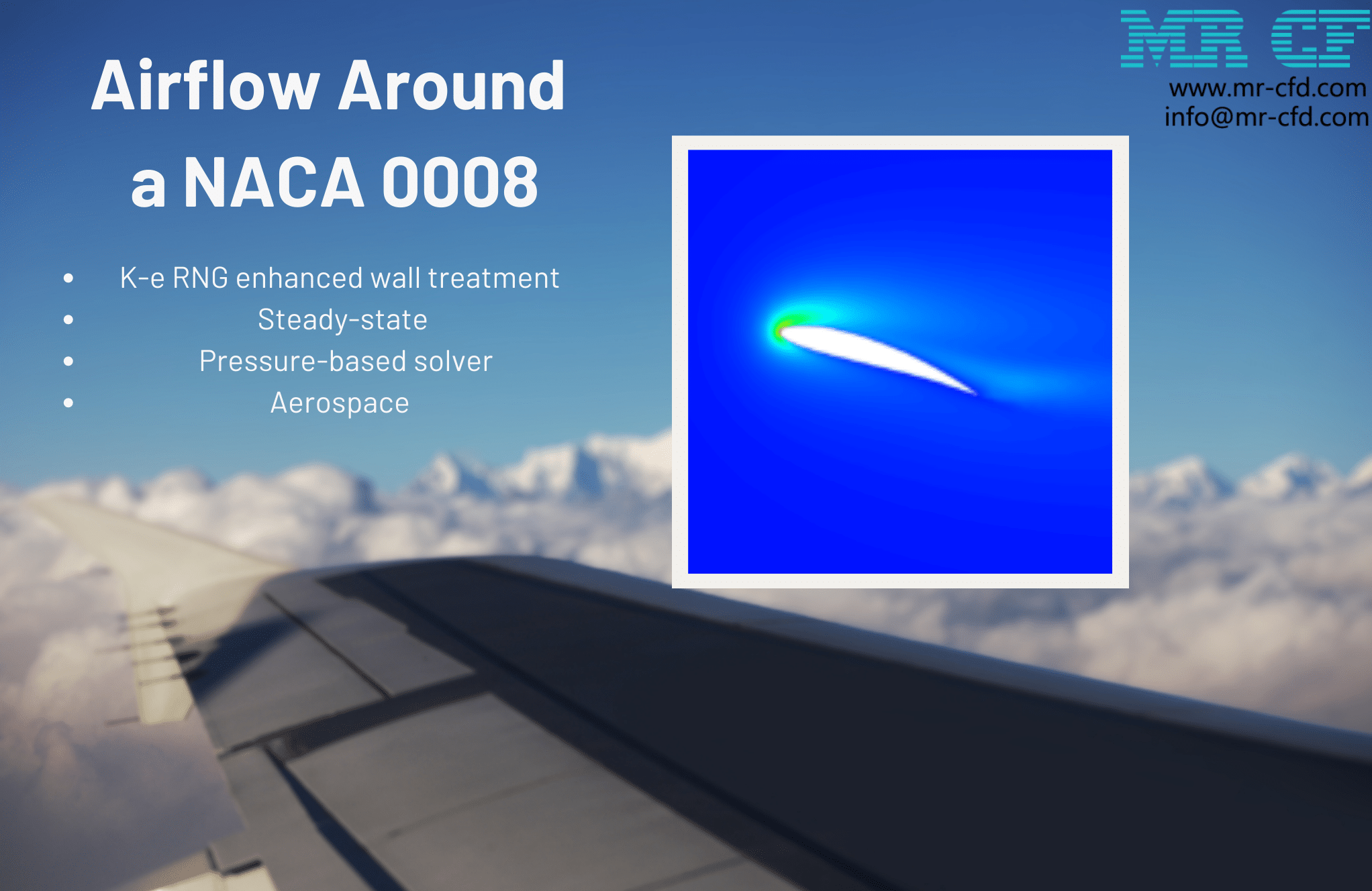
This project is going to simulate an airfoil in the airflow field with a 16-degree attack angle.
Click on Add To Cart and obtain the Geometry file, Mesh file, and a Comprehensive ANSYS Fluent Training Video.To Order Your Project or benefit from a CFD consultation, contact our experts via email ([email protected]), online support tab, or WhatsApp at +44 7443 197273.
There are some Free Products to check our service quality.
If you want the training video in another language instead of English, ask it via [email protected] after you buy the product.
Description
Airflow Around a NACA 0008 Airfoil CFD Simulation, ANSYS Fluent Training
Description
This project is going to simulate a NACA 0008 Airfoil in the airflow field with ANSYS Fluent software. Geometric defining parameters include chord line, angle of attack, leading edge, and trailing edge. The direction of the airflow into the body is defined by the angle of attack (the angle between the chord line of the airfoil and the direction of the oncoming air flow). The purpose of this paper is to investigate the behavior of airflow and pressure distribution, as well as to study drag and lift forces.
In the present case, the angle of attack is 16 degrees and the length of the chord and the width of the airfoil are assumed to be equal to 1. Also, we selected the maximum speed of 20.78736m/s for the inlet. Thus, to determine the drag force, the length of the chord must be multiplied by the sine 16 and then across the cross-section width, and to define the lift force, the chord length must be multiplied by the cosine 16 multiplied by the cross-section and then across the width. Therefore, the surface area for calculating the lift and drag forces is equal to the following values, which are defined in the reference values section.
The following figure gives a schematic of the structure of an asymmetric and its defining geometric parameters:
The 2-D geometry of the present model is drawn using the Design Modeler software. First, the coordinates of the points in the wall forming the desired airfoil are imported into the software, and then, using the called points, it is completely drawn in the software. The far-field boundary required for the analysis of airflow behavior is then drawn around the airfoil according to the relevant standards. The figure below shows an overview of the model’s geometry.
The meshing of the present model has been done using ANSYS Meshing software. The mesh type is unstructured and the element number is equal to 296533. The figure below shows a view of the meshing.
Airflow around an Airfoil Methodology
To simulate the present model, we considered several assumptions such as performing the pressure-based solver, the steady model is considered and we do not consider the effect of gravity on the fluid.
We used the k-epsilon RNG enhanced wall treatment model to simulate the fluid’s turbulence.
conclusion
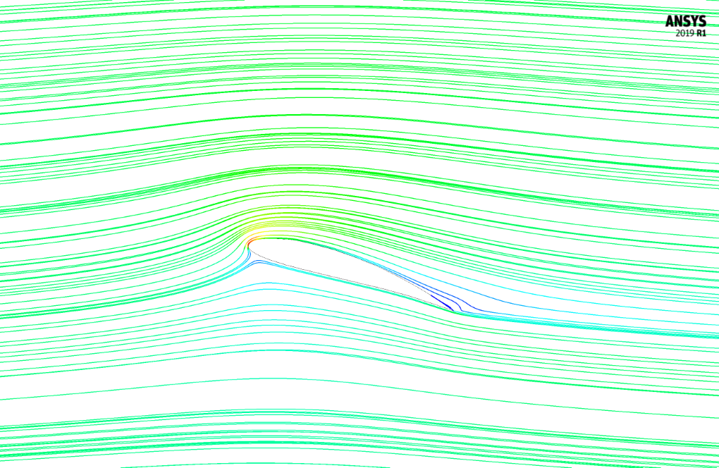
At the end of the airfoil solution process, we obtain two-dimensional contours of pressure, velocity, turbulent kinetic energy, as well as two-dimensional pathlines. Also, the value of drag and lift coefficient and forces have been obtained.


Larue Larkin –
Can I contribute to this simulation?
MR CFD Support –
We are open to contributions! Please share your ideas or suggestions.
Edmond Waelchi –
Can this simulation be used to optimize the airfoil design?
MR CFD Support –
Absolutely! The results from this simulation can be used to analyze the performance of the airfoil and make necessary design modifications for optimization.
Uriel Wuckert –
I’m deeply impressed with the attention to detail in the design and execution of the simulation for the NACA 0008 Airfoil using ANSYS Fluent. It’s evident from the comprehensive description that thorough consideration for geometrical specificity and boundary conditions was made to ensure a high-fidelity analysis of airflow characteristics. Well done!
MR CFD Support –
Thank you for recognizing our efforts in carrying out a detailed and high-quality simulation for the NACA 0008 Airfoil using ANSYS Fluent! We take pride in providing training materials that offer in-depth insights and allow our customers to fully understand the complexities of computational fluid dynamics simulations. We appreciate your compliments and are glad that you found the simulation impressive and insightful.
Zackary White –
By focusing on airflow and drag forces, this hands-on experience helped solidify my understanding of aerodynamics!
MR CFD Support –
Thank you for your kind feedback! We’re thrilled to hear that our ANSYS Fluent training on the NACA 0008 airfoil provided you with a clear understanding of aerodynamic principles. Your success is our goal, and we look forward to continuing to support your learning journey!
Aracely Willms –
I was truly impressed by the precision and detail of the Airflow Around a NACA 0008 Airfoil CFD Simulation with ANSYS Fluent Training. The use of the steady-state model and the k-epsilon RNG turbulence modeling provided clear insights into the flow characteristics, and the visualizations were top-notch. It certainly appears to be a comprehensive and practical training module for understanding airfoil aerodynamics.
MR CFD Support –
Thank you for highlighting the benefits of the Airflow Around a NACA 0008 Airfoil training. We’re pleased to know the precision, detail and comprehensive CFD simulations met your expectations. It’s our goal to provide learners with substantive, visually engaging instructional materials. We appreciate your recognition of our efforts and feedback on the training module’s practicality. If you have any further insights or require help, don’t hesitate to reach out. Thank you for choosing our learning products.
Phillipp T. –
Hi. Thanks for your tutorials.
When are we allowed to use the far-field boundary condition in our simulations?
melika maysoori –
Hi Phillipp. Hope u doing well. Actually Pressure Far-Field bc is used to model free-stream compressible flow at infinity, with prescribed static conditions and the free-stream Mach number. But there are some limitations :
1. This boundary condition is applicable only when the density is calculated using the ideal-gas law
2. It is incompatible with the multiphase models (VOF, mixture, and Eulerian) that are available with the pressure-based solver.
3. It cannot be applied to flows that employ constant density, the real gas model, and the wet steam model, which are available in the density-based solver.
Also, note that to effectively approximate true infinite-extent conditions, you must place the far-field boundary far enough from the object of interest.
😉
Yasmine Hamill –
I found the project on Airflow Around a NACA 0008 Airfoil extremely insightful. The detailed analysis on lift and drag forces along with the simulation set-up provided a clear understanding of the airfoil behavior at high angles of attack. Great work!
MR CFD Support –
We are thrilled to know that you found the simulation project on Airflow Around a NACA 0008 Airfoil helpful and insightful. Thank you for acknowledging the details and analysis we provided. Your positive feedback motivates us to continue delivering high-quality CFD training!
Cassidy Runte –
I’m impressed with the level of detail in the simulation’s methodology and conclusions. Can the results of the drag and lift coefficients be used to improve the design of real-life airfoils?
MR CFD Support –
Thank you for your positive feedback! Yes, the results of drag and lift coefficients obtained from CFD simulations like the Airflow Around a NACA 0008 Airfoil simulation can indeed be valuable for improving the design of real-life airfoils. By understanding the aerodynamic performance at different angles of attack and flow conditions, engineers can optimize airfoils for better efficiency and performance in specific applications.
Michale Gulgowski –
The training was absolutely remarkable! Well-structured content and truly insightful simulations. The contour results were very clear in showing how the airflow changes around the airfoil. Premium material for those interested in aerodynamics.
MR CFD Support –
Thank you so much for your kind words! We’re thrilled to hear you found the NACA 0008 airfoil training material insightful and well-structured. It’s always great to know our content is making a positive impact and is helpful for those passionate about aerodynamics. If you need any further learning resources or assistance, don’t hesitate to ask!
Nichole Kilback IV –
I’m thoroughly impressed with the intricacy and accuracy of the pressure and velocity contours generated in this NACA 0008 Airfoil simulation. The insights into drag and lift forces have significantly enhanced my comprehension of aerodynamic performance.
MR CFD Support –
Thank you for your kind words! We’re delighted to know that our NACA 0008 Airfoil CFD simulation has provided you with clear insights and an improved understanding of aerodynamics. If you have any more questions or need further assistance, feel free to reach out. We’re here to help with your learning journey.
Hipolito Muller –
I appreciate the detail in the methodology for simulating the NACA 0008 airflow. The technical aspects of the simulation, including the assumptions made and turbulence model used, were well-documented. It’s evident that precision was a key focus. Great work!
MR CFD Support –
Thank you for your positive feedback on the Airflow Around a NACA 0008 Airfoil simulation. We strive to provide detailed and accurate training materials, and we’re pleased to know that you found the information precise and helpful!
Neva Kuhn –
Three cheers for the clarity and detail in the Airflow Around a NACA 0008 Airfoil simulation! The thorough depth offered in studying the behavior of the airflow and forces in play is top-notch.
MR CFD Support –
Thank you very much for your positive feedback! It is our pleasure to hear that you found our simulation and training material thoroughly detailed and helpful for understanding the complex behaviors of airflow around airfoils. We aim to continue providing high-quality and informative content for our users.
Lavina Friesen –
that’s fantastic. Keep it up!
Mr. Jeremie Koelpin DVM –
This product really delivered on its promises! The detailed exploration into airflow dynamics around the NACA 0008 airfoil provided an excellent basis to understand aerodynamic phenomena. Thanks to this training, I feel more confident in using ANSYS Fluent for my projects. The clarity in addressing lift and drag forces was particularly useful for my research. Great job on constructing a comprehensive CFD course.
MR CFD Support –
Thank you for your kind words! We’re thrilled to hear that our ANSYS Fluent training has been so useful for your projects and research. Understanding the aerodynamics phenomena is crucial, and we’re glad our course could help clarify these concepts. We appreciate your feedback and we look forward to providing you with more valuable learning experiences in the future!
Ethyl Reichel –
The detailed simulation setup for the NACA 0008 Airfoil was remarkable. I learned so much about the effects of different angles of attack on airflow behavior.
MR CFD Support –
Thank you for your positive feedback! We are delighted to hear that our simulation on the airflow around a NACA 0008 Airfoil has enhanced your understanding of aerodynamics. If you have any more questions or need further learning materials, feel free to reach out to us!
Thelma Simonis –
I just completed my study with the Airflow Around a NACA 0008 Airfoil simulation package from MR CFD Company. The detailed explanations and the structure of the report helped me understand the concept of lift and drag in an airfoil with hands-on learning. Seeing the actual simulation with explained methodology was definitely the highlight for me!
MR CFD Support –
Thank you for your kind words! We’re thrilled to hear our Airflow Around a NACA 0008 Airfoil simulation product has been instrumental in your learning. At MR CFD Company, we strive to provide comprehensive and clear instruction to aid in understanding fundamental concepts. Your success is our priority, and we appreciate you taking the time to share your positive experience. If you need further assistance or guidance, please feel free to reach out to us!
Roselyn Hackett DDS –
Absolutely fantastic training material! The depth of the study on the NACA 0008 Airfoil was impressive, and the rigorous approach to validating the CFD model through ANSYS Fluent provided substantial learning value. The clarity in explaining how drag and lift forces were calculated at different angles of attack really cemented my understanding.
MR CFD Support –
We are thrilled to hear such positive feedback! It’s always rewarding to know that our training materials are helping others deepen their understanding of CFD principles and applications using ANSYS Fluent. Thank you for your kind words, and we hope that our products continue to support your learning journey!
Erich Schaden –
I’m blown away by the detail put into simulating the NACA 0008 airfoil. The dedication to accurately determining the lift and drag forces by accounting for the angle of attack and airfoil dimensions shows the thoroughness of the instruction. The ability to also understand the pressure distribution and airflow behavior is quite impressive. Fantastic work on creating an educational experience that feels so hands-on and practical!
MR CFD Support –
Thank you for your kind words and appreciation for our NACA 0008 airfoil simulation product! We’re happy to hear that you found the simulation instructions to be thorough and practical. Our goal is always to provide detailed and useful CFD learning experiences. It’s great to know that our efforts have been recognized. If you have any further questions or need assistance with other simulations, feel free to reach out. Enjoy your learning journey!
Theron Schuster I –
The comprehensive explanation of the project objectives, setup, and results is impressive. Your complete workflow from geometry creation to post-processing analysis of lift and drag coefficients seems meticulous and highly educational.
MR CFD Support –
Thank you for your positive feedback! We are thrilled to learn that our detailed workflow and simulation approach have met your educational needs. It’s always encouraging to hear that our efforts to provide clear and comprehensive training are appreciated by our customers. If you need further assistance or have more questions, feel free to reach out to us.
Deron Rodriguez –
I found the airflow simulation around the NACA 0008 airfoil quite intriguing. The level of detail in the report shows the thoroughness of the study. Notably, I appreciated how the angle of attack and boundary conditions were set to closely replicate the realistic conditions an airfoil would experience. Great work on both the meshing techniques and the selection of turbulence model to derive the aerodynamic coefficients.
MR CFD Support –
Thank you for your positive feedback! We always strive to provide accurate and detailed simulations to help understand complex aerodynamic phenomena. It’s pleasing to hear that our efforts in setting realistic conditions and producing a fine mesh have been acknowledged. Should you require further information or assistance, don’t hesitate to reach out.
Mara Dach –
I learned so much from the NACA 0008 Airfoil simulation training. It helped clarify many concepts like lift and drag forces calculations. Truly fascinating stuff!
MR CFD Support –
Thank you for your positive review! We’re thrilled to hear that our training on the NACA 0008 Airfoil simulation in ANSYS Fluent was helpful and enlightening. Understanding lift and drag is fundamental in aerodynamics, and we are glad you found the material fascinating. We appreciate you taking the time to share your experience and we look forward to providing you with more valuable learning materials!
Eusebio Pacocha DVM –
I’m really impressed with how detailed and comprehensive the simulation was. The use of unstructured mesh and the k-epsilon RNG turbulence model must have provided great insight into the airflow characteristics around the NACA 0008 Airfoil.
MR CFD Support –
Thank you for your kind words! We put a lot of effort into ensuring our simulations are as precise and instructive as possible. It’s wonderful to hear that the level of detail in the NACA 0008 Airfoil simulation met your expectations and provided valuable insights.