Side Supply Air Conditioning, Paper CFD Validation
$160.00 Student Discount
- The problem numerically simulates Air Conditioning (Side Supply) using ANSYS Fluent software.
- This project is validated with a reference article.
- We design the 3-D model by the Design Modeler software.
- We mesh the model with ANSYS Meshing software, and the element number equals 1027974.
- The Energy Equation is activated, and heat flux is applied to the walls as heat sources.
To Order Your Project or benefit from a CFD consultation, contact our experts via email ([email protected]), online support tab, or WhatsApp at +44 7443 197273.
There are some Free Products to check our service quality.
If you want the training video in another language instead of English, ask it via [email protected] after you buy the product.
Description
Air Conditioning (Side Supply), Paper Numerical Validation using ANSYS Fluent Training
The present problem simulates the HVAC process through a side-supply air conditioning system in an office using ANSYS Fluent software. We perform this CFD project and investigate it by CFD analysis.
This simulation is based on the information from a reference article [Comparison of air-conditioning systems with bottom-supply and side-supply modes in a typical office room], and its results are compared and validated with the results in the paper.
The simulation is performed for a state of the paper where the side-supply air conditioning system is designed.
The present model is designed in three dimensions using the Design Modeler. The present model is related to the interior of a room with a length and width of 6 m, 4 m, and a height of 3.5 m.
Inside the room, four people, four desks, four computers, and six heat sources are designed, Assuming that these items have a very simple geometric structure in the form of cylinders and cubes. Four entrance borders are defined on the room’s sidewalls, and two exit borders are defined on the ceiling of the room.
The meshing of the present project has been done using ANSYS Meshing software. The element number is 1027974.
Side Supply Methodology
Based on the design of the air conditioning system in the mentioned article, two panels have been designed to enter fresh air in two opposite walls; In this way, air enters the room through four panels (each wall has two panels).
The air inside the room then exits to the outside environment through two panels on the room’s ceiling.
The inlet air of the air conditioner system has a velocity of 0.21 m/s and a temperature of 21 ºC. Inside the room, four people, four computers on the table, and six heat sources are designed.
In fact, according to the article, first the experimental work and then a numerical study was done; So that for each of the factors in the interior of the room, a certain amount of energy is considered, and to simplify the work, simple geometries are used to define these heat sources.
Four humans are defined as cylinders with 150 W energy, four computers as small cubes placed on tables with 150 W energy, and six heat sources with 200 W energy.
To define these heat sources, the thermal flux boundary condition on the walls of these energy sources is used; By dividing this energy on the outer surface of the walls of these heat sources, the desired amount of heat flux is obtained.
In addition, the room’s outer walls have a constant temperature of 26 ºC, and the surfaces of the tables are defined as insulation. Moreover, the RNG k-epsilon model and energy equation are enabled to solve the turbulent fluid equations and calculate temperature distribution.
Side Supply Conclusion
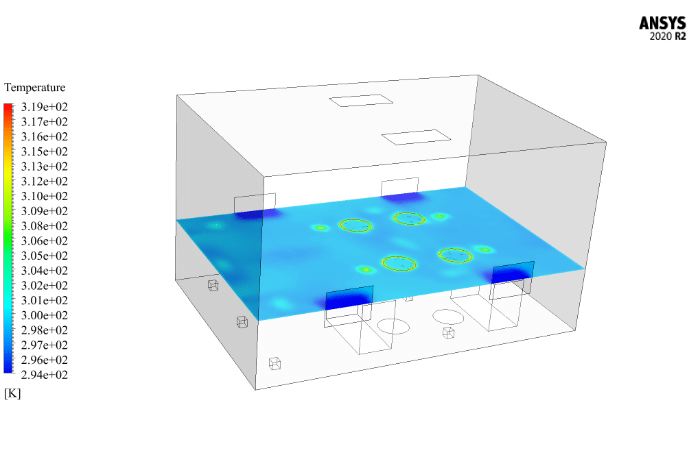
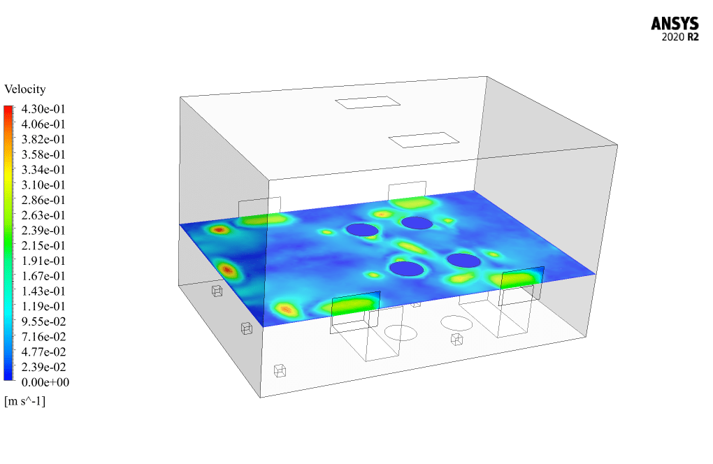
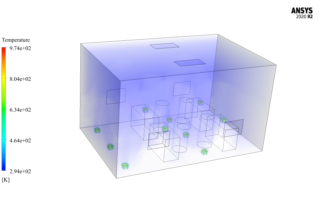
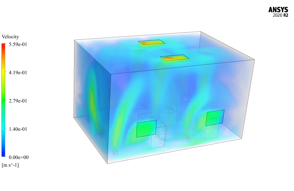
At the end of the solution process, two- and three-dimensional contours related to the temperature and velocity inside the room are obtained. The validation of the present simulation is performed based on diagrams “a” and “b” from Figure 9 of the mentioned article.
These diagrams show the temperature changes in terms of height from the floor of the room. A height of 2 meters from the ground floor includes ten measuring points at a distance of 0.2 meters from each other.
Figure a shows the location of E, which is longitudinally 3 meters from the two walls and transversely is 1.6 meters and 2.4 meters from the other two walls; While diagram b shows the location F, which is facing longitudinally at a distance of 3 meters from the two walls and transversely at a distance of 3.2 meters and 0.8 meters from the other two walls.
Then, for each of the locations E and F, ten sample points are considered for measuring from a distance of 0.2 m from the floor to a distance of 2 m from the floor, and a graph of temperature changes in these points is obtained.
Figures show the temperature changes in height in two locations, E and F, respectively. According to these graphs, the current numerical simulation results are compared with the results in the paper.



Dr. Rick Borer II –
I truly enjoyed seeing how MR CFD’s training allowed me to validate a complex HVAC system using ANSYS Fluent. The side supply air conditioning simulation provided tangible results that matched with published research, which gives me great confidence in the reliability of these simulations for future projects.
MR CFD Support –
Thank you so much for taking the time to leave such a thoughtful and positive review! We’re thrilled to hear that our training materials and the validation process met your expectations and provided you with reliable results. It’s great to know that you feel confident in using our simulations for your future projects. We appreciate your feedback and look forward to continuing to support your learning and simulation needs!
Winifred Reichert –
What was the reason for choosing the RNG k-epsilon model and energy equation in this simulation?
MR CFD Support –
The RNG k-epsilon model is selected for its enhanced accuracy in predicting the turbulent fluid flow, particularly where there are strong recirculations or complex flow patterns. Moreover, incorporating the energy equation allows us to accurately compute the temperature distribution within the room considering the thermo-physical interactions due to various heat sources and the HVAC system.
Antwon King –
I was fascinated with the simulation setup for the Side Supply Air Conditioning system! The level of detail in replicating the study looks comprehensive. Could you detail how the RNG k-epsilon model contributes to the accuracy of the simulation, especially regarding temperature distribution around the heat sources?
MR CFD Support –
The RNG k-epsilon model is an advanced turbulence model that provides detailed simulations of airflow patterns and turbulent eddies, which influence the temperature distribution within a space. In the case of the Side Supply Air Conditioning simulation, this model helps accurately predict the flow of cooler air from the AC outlets and its interaction with the heat given off by the heat sources like computers and humans in the room. It generates reliable results for the temperature variations and airflow velocity by accounting for the effects of thermal plumes and turbulences caused by these heat sources, allowing for a nuanced comparison with real-world experimental data.
Issac Corwin –
The training provided detailed insight into side supply air conditioning systems. The simulation based on a real academic paper added credibility and provided an excellent learning experience. Utilizing ANSYS Fluent for both temperature and airflow analysis within a room not only taught me how the software operates, but also gave context on its application in practical HVAC design.
MR CFD Support –
Thank you for recognizing the value of the simulation and its educational aspects. We’re pleased to hear that our product has effectively contributed to your understanding of ANSYS Fluent application in HVAC system design. Your satisfaction is a reassuring sign that we’re making helpful and impactful training materials. We appreciate your positive feedback!
Dylan Langworth –
I found the comparison of the simulation to actual measurements especially fascinating. How closely did the temperature distribution results in the simulation match the measurements from the article?
MR CFD Support –
In the simulation, temperature distribution values matched very closely with the measurements cited in the article, indicating a high level of accuracy in numerical modeling. Minor discrepancies were within acceptable ranges, confirming the effectiveness of the computational models used.
Prof. Hassie Grady –
Outstanding training material! I was genuinely impressed by how accurately the simulation matched the experimental results from the reference article. It highlighted the capability of ANSYS Fluent in simulating HVAC systems and demonstrated the meticulousness of MR CFD Company in setting up and running the simulation. Excellent work in conducting such a thorough validation process and providing clear insights into temperature and velocity distributions within the room.
MR CFD Support –
Thank you so much for your positive feedback! We pride ourselves on providing high-quality training materials and conducting precise CFD simulations matched with experimental data. It’s fantastic to hear that our efforts have aided in your understanding of HVAC system simulation in ANSYS Fluent. We appreciate your recognition of the rigor in our validation processes. Let us know if there’s anything else we can help you with in your learning journey!
Jerrell Fadel –
The Side Supply Air Conditioning simulation seems incredibly comprehensive. I’m particularly interested in knowing how accurately the temperature distribution within the room was replicated from the experimental data in the reference paper. Could you provide some insight into how well the simulation matched with the paper’s results?
MR CFD Support –
The accuracy of the temperature distribution in the Side Supply Air Conditioning simulation was thoroughly validated against the data from the reference paper. Comparison graphs were created for two specific locations, designated as E and F in the room. These were based on measurements taken from the floor up to 2 meters at 0.2-meter intervals. The comparison shows that the simulation closely replicates the temperature distribution obtained in the paper’s experimental data. The results provide a successful validation of the CFD model, showcasing the reliability of the simulation process used by MR CFD Company.
Korbin Metz –
Very impressed with the level of detail in the side supply air conditioning simulation! The comparison with paper results provided reassuring accuracy. Fantastic learning tool!
MR CFD Support –
Thank you for your positive feedback! We are thrilled to hear that you found our simulation to be a precise and helpful learning resource. If there’s anything else we can do to assist you or enhance your experience, please let us know.
Reynold Macejkovic –
The CFD simulation is so detailed and attentive to the factors related to HVAC system performance. The comparison with a paper ensures this method isn’t just theoretical. The mention of validation diagrams makes it an excellent tool for learning and confirming numerical models with experimental data. Well done!
MR CFD Support –
Thank you for your kind words! We’re delighted to hear that our thorough approach to simulating the HVAC system and validating it against established research was helpful. Ensuring our learning products are both accurate and educational is paramount to us. If you have any further questions or wish to explore other scenarios, don’t hesitate to reach out.
Mr. Marley Kassulke –
I found the comparison of the simulation results with experimental data intriguing. Can you specify the measures taken to ensure that the simulation setup closely matched the experimental setup used in the reference article to attain valid comparisons?
MR CFD Support –
In order to closely match the simulation setup with the experimental setup used in the reference article, several measures have been taken including: detailed replication of the geometry as per article specifications, precise setting of thermal flux boundary conditions for the heat sources in the room, adherence to the correct input velocities and temperatures for the air entering the room, and implementation of the RNG k-epsilon turbulence model for accurate capture of fluid flow characteristics. Additionally, energy equations have been solved to predict accurate temperature distributions. This meticulous approach has been adopted to minimize discrepancies between the simulation and the experiment and enable a legitimate validation of the CFD model with the published data.
Hillary Keeling –
I was thrilled with the thorough simulation of the HVAC side supply air conditioning setup. The attention to heat sources and the way energy is distributed by simple geometries within the model were quite impressive. It is especially commendable to see the validation against experimental data, helping to ensure the accuracy and reliability of the simulation outcomes.
MR CFD Support –
Thank you very much for your positive feedback! We’re delighted to hear that the simulation and its validation against empirical data met your expectations. At MR CFD, we strive to provide accurate and thorough analyses, and it’s gratifying to know that our attention to detail is appreciated by our clients. If you have more questions or need further assistance in the future, please don’t hesitate to contact us.
Ms. Dariana Marquardt MD –
I found the comparison to the reference article very insightful. It’s great to see the simulation align with the published results which gives me confidence in the accuracy of your CFD analysis!
MR CFD Support –
We’re delighted to know that our product has met your expectations and that the validation against the reference article has provided you with confidence in our CFD analysis. We strive for accuracy and it’s rewarding to see it being recognized. Thank you for your positive feedback!
Ms. Elaina Walter –
The methodology insights provided are so thorough! It clarifies how the simulation mirrors the conditions set forth in the research paper. Did the results from the CFD simulation closely match the empirical data from the paper, especially regarding temperature distribution at distinct elevations within the room?
MR CFD Support –
Thank you for your kind words about our attention to methodology; we strive to ensure a thorough explanation. To answer your question, yes, the CFD simulation results closely matched the empirical data from the reference paper, especially the temperature distribution at different heights within the room. We conducted a detailed validation process that involved comparing temperature changes at specific measurement points within the room, as outlined in diagrams from the paper. The alignment with empirical data underscores the accuracy and reliability of our simulation process.
Felton Nienow –
The energy output from each person in the simulation seems quite specific. Could you tell me how this was determined?
MR CFD Support –
In the present CFD project, the amount of energy output from each person is based on values generally used in thermal comfort studies and HVAC design. Specifically, a metabolic rate of 150 W per person is a standardized estimate for a seated, office-working adult. This information, along with extensive experimental data, allows the simulation to approximate realistic thermal loads within the office environment.
Mrs. Mikayla Kilback –
The detail level of your simulation is impressive, especially how it compares to the experimental data in the article cited. It’s clear that the systematic setup has helped create an accurate representation of an actual office environment. Great work on adjusting the heat sources and airflow to match the real-life conditions!
MR CFD Support –
We genuinely appreciate your positive feedback! It’s gratifying to know that our meticulous effort to match the simulation conditions to the study has been recognized. If you need any further information or assistance with similar analyses, please don’t hesitate to reach out. Thank you for taking the time to review our product.
Heaven Pouros Jr. –
Extremely impressed with the level of detail in the Side Supply Air Conditioning simulation! The methodological approach to validation against empirical data enhances my trust in the CFD analysis. It seems like a valuable learning tool for understanding the dynamics of air supply in an office.
MR CFD Support –
Thank you for your appreciative feedback! We strive for precision and relevance in our CFD simulations, and we’re glad that our dedication to accurate validation resonates with you. It is indeed our goal to provide useful toolsets for in-depth learning and understanding of environmental air flow. We look forward to continuing to support your exploration of fluid dynamics!
Efren McGlynn –
The training was crystal clear and incredibly valuable. The step-by-step solution matched the paper’s data remarkably, and the temperature distribution observations were so eye-opening! It enhanced my understanding of side supply air conditioning systems enormously.
MR CFD Support –
Thank you for such positive feedback! We’re delighted to know the training was crystal clear and valuable to you. It’s great to hear the temperature distribution insights were eye-opening. We strive to provide detailed simulations that can deepen understanding. Your complement is much appreciated!
Audra Hartmann –
The product reviews that I’m seeing here are impressive! The attention to detail and the thorough description of how the simulation compares to the referenced article for validation is very professionally presented. I have to commend MR CFD Company on this training material. Had a great learning experience grasping HVAC dynamics using ANSYS Fluent. Cheers to the team for puting together such a well-structured and informative tutorial!
MR CFD Support –
Thank you for your kind words and positive review! It’s heartening to hear that our Side Supply Air Conditioning, Paper CFD Validation training material has provided such value to you. We strive to create detailed and comprehensive content to enhance the learning experience of our users, and we are glad you found it helpful. If you have any more feedback or need further assistance, please feel free to reach out. Your success is very important to us!