Air Intake of Gas Turbine Considering Fogging System, CFD Simulation ANSYS Fluent Training
$120.00 Student Discount
In this project, a part of the air intake duct of the gas turbine is simulated, considering the fogging system via Ansys Fluent.
Click on Add To Cart and obtain the Geometry file, Mesh file, and a Comprehensive ANSYS Fluent Training Video.To Order Your Project or benefit from a CFD consultation, contact our experts via email ([email protected]), online support tab, or WhatsApp at +44 7443 197273.
There are some Free Products to check our service quality.
If you want the training video in another language instead of English, ask it via [email protected] after you buy the product.
Description
Introduction
The gas turbine efficiency is highly dependent on the inlet temperature supplied by ambient air. Thus, by decreasing the inlet temperature, the gas turbine performance could be significantly improved. The fogging system is one of the best solutions that work by injecting billions of water droplets into the inlet duct and causing a decrease in intake temperature by evaporating.
Air Intake of Gas Turbine Considering Fogging System Problem Description
In this project, a part of the air intake duct of the gas turbine is simulated, considering the fogging system. Air enters the first section of the duct at 2m/s velocity magnitude and encounters millions of water droplets after passing through a nozzle. The aim of the study is to investigate the effect of fogging system on temperature. We have used discrete phase model (DPM) and Species Transport Model in this simulation.
Geometry & Mesh
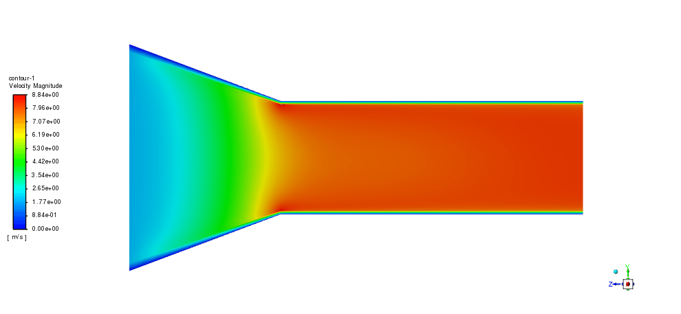
The 3D geometry is modeled in Ansys Design Modeler software. A 15*15m duct is connected to a 7.5*7.5m duct (figure 1). Also, the mesh grid is carried out using Ansys Meshing software. Furthermore, a structured grid is generated to keep computational costs at optimal conditions. Therefore 108000 elements established the fluid domain.
CFD Simulation
Several assumptions have been considered to simulate the fogging system in the gas turbine air intake, including:
- The simulation is Transient to investigate the fogging system’s influence over time.
- The pressure-based solver type is used due to the incompressibility of the working fluid.
- Gravitational acceleration effects are applied in the –y-direction.
The following table represents a summary of the solution:
| Models(Viscous) | ||||
| Viscous | K-epsilon | Standard | ||
| Species | Model | Species Transport | ||
| Discrete phase Model | Interaction | Interaction with continuous phase | ||
| DPM iteration interval | 10 | |||
| Particle Treatment | Unsteady Particle Tracking
Track with fluid flow time step |
|||
| Injections | Particle Type: Droplet | |||
| Injection Type: Surface
Material: Water-liq Evaporating Species: h2o Diameter: 1e-5 Temperature: 283K Velocity Magnitude: 1m/s Total Flow Rate: 5kg/s |
||||
| Materials | ||||
| Fluid | Definition method | Fluent database | ||
| Material name | Air | |||
| Droplet Particle | Water-liq | |||
| Cell zone condition | ||||
| Material name | Mixture-template | |||
| Boundary condition | ||||
| Inlet | Type | Velocity inlet | ||
| Velocity magnitude | 2m/s | |||
| Turbulent intensity | 5% | |||
| Turbulent viscosity ratio | 10 | |||
| Outlet
Wall |
Type | Pressure-outlet | ||
| Gauge Pressure | 0 | |||
| Type | Wall
(Stationary – No-slip condition) |
|||
| Solver configuration | ||||
| Pressure-velocity coupling | Scheme | SIMPLE | ||
| Spatial Discretization | Gradient | Least squares cell-based | ||
| Pressure | Second order | |||
| Momentum | Second-order upwind | |||
| Turbulent kinetic energy | First-order upwind | |||
| Turbulent dissipation rate | First-order upwind | |||
| Energy | First-order-upwind | |||
| H2o | First-order-upwind | |||
| Initialization | Initialization methods | Standard Initialization | ||
| Run Calculation | Time step size | 0.01 | ||
| Max iteration/time step | 20 | |||
Air Intake of Gas Turbine Considering Fogging System Results
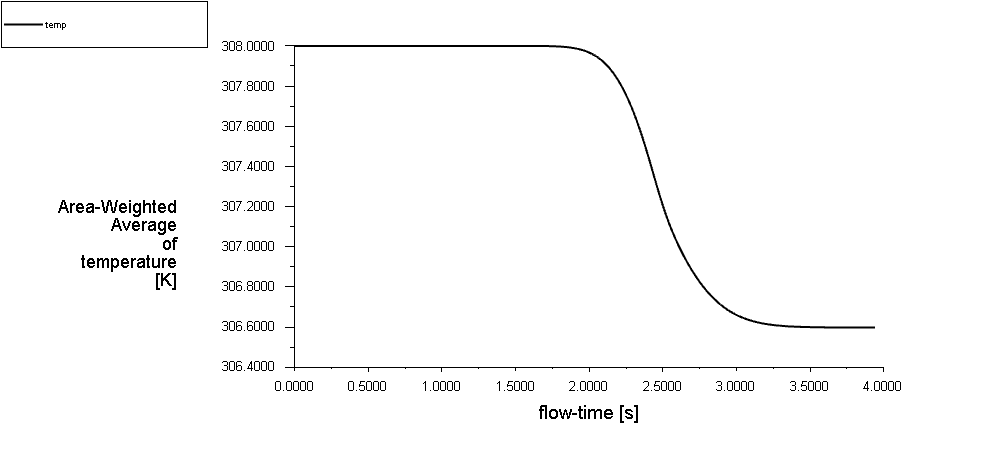
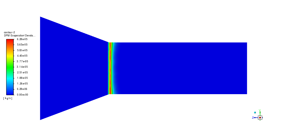
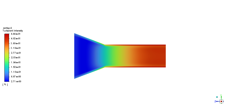
After the simulation process, 2d & 3d contours are extracted. As seen in the outlet’s temperature report, the droplets could be evaporated by receiving heat from the air due to the temperature gradient. As a result, the temperature falls to 306.5K. Note that, in the industries, the air intake ducts are designed giant that could pass a large mass flow. Besides, the total number of droplets is higher, but considering the study aim, we have simplified it to reduce computational costs.



Ethelyn Emmerich –
The description was really insightful! I found the details intriguing and informative. Could you clarify what exactly impacts the rate at which the water droplets evaporate?
MR CFD Support –
Thanks for your positive feedback! The evaporation rate of water droplets is influenced by several factors, including the temperature and humidity of the intake air, the temperature gradient between the droplets and the surrounding air, the size and distribution of the droplets, and airflow dynamics within the intake duct. The provided CFD simulation models these conditions to predict evaporation rates accurately in the fogging system of the gas turbine engineering process.
Mr. John Bashirian IV –
I am thrilled with how the training for the Air Intake of Gas Turbine Considering Fogging System has improved my understanding of the simulation process in ANSYS Fluent. The handling of the DPM along with the Species Transport Model was intricate and this training made it approachable. The temperature decrease at the outlet clearly showed the efficiency of the fogging system which was quite an enlightening study. Great job simplifying a complex process for educational purposes!
MR CFD Support –
Thank you for your positive feedback! We’re really glad to hear that you found the training helpful and that it improved your understanding of the complex processes within ANSYS Fluent. It’s our goal to simplify and clarify the subjects of CFD for educational purposes. We appreciate your comments and are pleased to know that the simulation training effectively demonstrated the efficiency of the gas turbine’s fogging system. Thank you for choosing our services!
Prof. Dale Hartmann II –
The explanation of the fogging system is really enlightening! It clearly shows how the inlet temperature affects the turbine performance. Well done on simulating such a complex interaction between the droplets and the air.
MR CFD Support –
Thank you for your kind words! We are glad to hear that our simulation could provide clear insights into the complex interactions within a gas turbine’s fogging system. Understanding how temperature impacts turbine efficiency is critical, and we strive to deliver quality training that helps illuminate these aspects. We appreciate your feedback!
Rowena Beer Sr. –
The training was very clear and the examples provided made it easy to understand the process and results!
MR CFD Support –
Thank you for your positive feedback! We’re thrilled to hear that our training material was clear and helpful to you. Understanding the complex workings of CFD simulations like the one for the gas turbine air intake with a fogging system is our goal. If you have any more questions or need further assistance in the future, feel free to reach out!
Gaylord Quigley –
I was very pleased with the detailed explanation of how the fogging system can impact gas turbine efficiency. The use of DPM and the Species Transport Model in the simulation was well articulated. The results clearly show the effect of temperature change due to fogging nozzles, which is vital for the design considerations in the industry.
MR CFD Support –
Thank you for your positive feedback! We’re delighted to hear that our explanation on the fogging system’s impact on gas turbine efficiency met your expectations and provided you with the necessary insights. If there are any more aspects of our simulations or other products that interest you, don’t hesitate to reach out or explore further. We appreciate your support and are here to assist with any additional information or questions you may have.
Kathleen Torphy –
The training was much clearer than fog! Helped me understand how fogging systems enhance gas turbine efficiency. Impressed by how it covers both theory and applied simulation techniques.
MR CFD Support –
Thank you for your kind words! We’re thrilled to hear that you found the training clear and informative. It’s great to know that it enhanced your understanding of fogging systems in relation to gas turbine efficiency. If you have any further questions or need more insight into CFD simulations, feel free to reach out!
Dr. Monserrat McDermott –
I’m impressed with the detail that has gone into simulating the air intake of a gas turbine using a fogging system. The results sound very promising for cooling efficiency improvements!
MR CFD Support –
Thank you for your kind words! We’re glad you recognize the effort we put into our simulations to ensure they are as detailed and accurate as possible. It’s great to hear that our product has met your expectations in illustrating the benefits of a fogging system in enhancing gas turbine cooling efficiency.
Maggie Lakin Jr. –
I found the explanation about the droplet injection material and droplet size settings to be very clear. Thank you for providing these details, as they are critical for understanding how tiny water particles can affect air temperature.
MR CFD Support –
Thank you for your compliments! We strive to offer clear and detailed explanations to ensure users fully understand the nuances of the complex simulations. If you have any more questions or require further information, feel free to ask. We’re here to help!
Merle Hammes –
I’m really impressed with the detail and complexity of the simulation for the air intake of a gas turbine using a fogging system! The use of DPM and Species Transport Model sounds like it provides accurate insights into temperature changes, which is critical for turbine efficiency. It’s also great to know that the model accounts for particle tracking and interaction with the continuous phase, thus showing the immediate effect of fogging on temperature. Well done MR CFD Company on this comprehensive fluid dynamics analysis!
MR CFD Support –
Thank you for your appreciation of our air intake simulation with a fogging system for gas turbines. We’re glad that you found the analysis detailed and informative. The combination of DPM and Species Transport Model indeed allows us to accurately study the temperature modification effects and its importance for the efficiency of gas turbine systems. If you ever have questions or need further insights on any of our products, don’t hesitate to reach out.
Abigail Bartoletti PhD –
This product made it so clear how the fogging system impacts gas turbine efficiency! The report clarifies how droplet evaporation reduces intake air temperature. But how do you ensure accuracy in modeling the droplet size and distribution in the duct?
MR CFD Support –
Thank you for your compliment on our product’s clarity regarding the fogging system’s effect on gas turbine efficiency. To ensure accuracy in the model, the droplet size and their distribution within the intake duct is determined based on realistic conditions and validated through experimental data or authoritative references in the field, if available. We precisely control the droplet size by setting up an appropriate injection mode in the DPM, and we account for an adequate distribution through careful positioning and orientation of the nozzles. Additionally, numerical simulations like these are typically calibrated by physical trial results or scaled down models where available, which aids in ensuring that the simulation results are reliable and reflective of real-world performance.
Prof. Izaiah O’Connell II –
Wonderful! The simulation of the air intake with the fogging system was extremely insightful. I particularly appreciate how the discrete phase model was leveraged to illustrate the interactions between the air and the fog droplets. It’s compelling to see the temperature decrease quantified, affirming the efficiency of the fogging system. The detailed explanation of the setup and results really helped me deduce how significant temperature management is in the performance of gas turbines. Thank you for an excellent tutorial.
MR CFD Support –
We’re thrilled to hear that you’ve found this simulation insightful and helpful in understanding the effects of the fogging system on gas turbine air intake. It’s amazing to see our tutorial contributing to your understanding of temperature management and its critical role in enhancing turbine efficiency. Thank you for your positive feedback, and please don’t hesitate to get in touch if you have any more questions or need further assistance with any of our products.
Kris Krajcik –
I’ve been absolutely impressed with the air intake simulation considering a fogging system! The detailed methodology of the simulation is as meticulous as it is fascinating. Given the complexity, I reckon this program helps in making informed decisions when implementing fogging systems.
MR CFD Support –
Thank you for your complimentary review! We’re thrilled to hear that you find the air intake simulation with the included fogging system both detailed and insightful. It’s great to know that our product could be of substantial aid in understanding and improving gas turbine efficiency through inlet temperature control. Your acknowledgment motivates us to keep providing high-quality training materials.
Mr. Troy Lebsack V –
This training course seems comprehensive. However, I wonder if there was any specific reason behind choosing a 0.01 time step size for the calculation? Would different time step sizes significantly alter results, especially regarding droplet evaporation in the simulation?
MR CFD Support –
Thank you for your interest in the training. The selected time step size of 0.01 is usually a balance between simulation accuracy and computational effort. It is small enough to capture the transient effects of droplet evaporation but also reasonably large to keep simulation times manageable. Using a different time step could change the results if the transient behavior of the system has specific time-scale sensitive phenomena. A sensitivity analysis on the time step size is often performed to ensure that such a choice yields accurate results without excessively increasing computational demands.
Danielle Powlowski –
The product comprehensively allowed me to understand the significance of fogging system in gas turbines and its intricate details of simulation using ANSYS Fluent. The level of detail in setting parameters and the well-explained geometry made it much clearer the effect of droplet size, material data and injection types on temperature conditions within a turbine’s intake duct.
MR CFD Support –
Thank you for your positive feedback! We’re delighted to hear that you found our product informative and educational, particularly concerning the functioning of the fogging system in gas turbines using ANSYS Fluent. It’s great to know that the details provided on setting up the simulation parameters enhanced your understanding of the impact of droplet size and other factors. We appreciate your appreciation for the complexity and precision required in such simulations. Your insights are valuable to us, and if you ever have more questions or need further assistance, we’re just a message away!
Tiana Zemlak –
What implications would this fogging system have on turbine longevity and maintenance, considering the potential moisture increment in the system?
MR CFD Support –
If not properly designed or managed, introducing additional moisture into the gas turbine system through fogging could lead to corrosion or fouling, potentially impacting the turbine’s longevity and increasing maintenance requirements. Proper materials and coatings, as well as maintenance practices, need to be established to mitigate these risks.
Mr. Manley Schiller –
Is it possible to observe the actual evaporation of droplets within the air intake duct in the simulation results, and how does this affect the air temperature?
MR CFD Support –
Yes, it is possible to observe the evaporation of water droplets within the intake duct in the simulation. The Species Transport Model and Discrete Phase Model are employed to track the water droplets’ behavior as they interact with the air. As the droplets evaporate, they absorb heat from the surrounding air, causing the air temperature to decrease. This effect is visible in the temperature contours resulting from the CFD simulation, showing a drop to 306.5K. Understanding how the evaporation impacts the air temperature is crucial for optimizing turbine efficiency.
Scottie McCullough DVM –
After evaporating, how do the water droplets affect the air’s properties in the simulation? Do they change the humidity level or any other factors?
MR CFD Support –
In the simulation, after the evaporated water droplets interact with the air, they lead to a decrease in air temperature, exemplified by temperature falling to 306.5K. They do indeed change the humidity level, which is accounted for in the Species Transport Model. Both temperature and humidity changes are significant for evaluating the performance efficiency of the gas turbine.
Mrs. Belle Torp –
Is the model accounting for variations in ambient temperature throughout the day in real operational conditions?
MR CFD Support –
In this simulation, ambient temperature variations throughout the day are not directly accounted for. The inlet temperature is set at a constant value for the purpose of this study, and the effects of the fogging system on that specific temperature are observed. Variations in ambient temperature would require either additional simulations for different temperatures or a more complex setup that includes temperature changes over time.
Jedidiah Schneider –
Can you explain how the interaction between water droplets and air flow is modeled in the simulation?
MR CFD Support –
The interaction between water droplets and air flow in the simulation is modeled using the Discrete Phase Model (DPM) in conjunction with the Species Transport Model. During the simulation, the DPM allows tracking of millions of water droplets as they interact with the continuous air phase. The fogging system’s impact is captured by monitoring particle tracking and evaporation over time, which results in a decrease in inlet temperature due to the heat exchange between air and evaporating droplets.
Vergie Auer –
The tutorial was incredibly comprehensive, guiding me meticulously through the turbulent model and water evaporation process. The details on setting up the discrete phase model and the species transport make it much clearer how the water droplets interact with the air temperature.
MR CFD Support –
Thank you for your positive feedback! We’re delighted to know that the tutorial was informative and helpful to you. It’s great to hear that the details provided clarity on the interaction between droplet evaporation and air temperature regulation. Should you have any further inquiries or need assistance with any other CFD simulations, feel free to reach out to us.
Ms. Mariana Cremin MD –
The attention to detail in both the material definitions and boundary conditions is impressive. It seems like all considerations for a real-world application of fogging systems in gas turbine air intakes have been taken into account. Can you tell me a bit more about how the evaporating of the water droplets effectively reduces the temperature inlet, as I’m interested to see how much of an impact the fogging system makes in a practical scenario for energy efficiency?
MR CFD Support –
We are thrilled you find the product impressive! The effectiveness of the fogging system is rooted in the principle of evaporative cooling. As the water droplets injected into the air stream begin to evaporate, they absorb heat from the surrounding air. This absorption of heat is what causes a decrease in the air temperature. In this simulation, you can observe that temperature at the outlet drops significantly due to the presence of evaporating droplets, which pulls energy from the airstream. The result is an effective lowering of the inlet air temperature to the turbine, optimizing its performance by increasing efficiency.
Linwood Dibbert –
I just finished the gas turbine air intake CFD course utilizing the fogging system. I must say, observing the temperature drop in the simulation was enlightening. A great application of the DPM and I was particularly impressed by the structured grid which helped streamline the computational load. Learnt a lot!
MR CFD Support –
Thank you for your positive review! We’re delighted to hear that you found the course enlightening and that you were able to see the practical applications of the Discrete Phase Model and appreciate the efficiency of the structured grid. If you have any more questions or need further assistance, don’t hesitate to reach out!
Marielle Stiedemann –
This training sounds impressive! The detail in the simulation setup seems very thorough. Can you comment on how the temperature drop might affect turbine longevity besides efficiency?
MR CFD Support –
Admin here, thanks for your kind words! In addition to improving efficiency, lowering the inlet temperature with a fogging system can potentially enhance the longevity of a gas turbine by reducing thermal stress and fatigue in turbine components. Cooler intake air means materials within the turbine are subjected to lower operating temperatures, which can decrease the rate of wear and tear, leading to a longer service life.
Makenna Wolff –
The course has streamlined the complex process of simulating a gas turbine’s air intake with a fogging system. I appreciated the detailed setup for the DPM and the Species Transport Model, which made understanding the steps easier. Great work on explaining the mesh and geometry preparation and loved the simplicity of the outcome analysis.
MR CFD Support –
Thank you for your positive feedback! We’re delighted to hear that you found the course useful and clear, particularly with the detailed explanations on DPM and Species Transport Model setup, as well as mesh and geometry handling. If you have further interest or need assistance with advanced simulations, feel free to reach out. We’re here to help enhance your CFD skills!
Vivianne Grant –
I purchased the Air Intake of Gas Turbine Considering Fogging System CFD Simulation tutorial and it significantly enhanced my understanding! The step-by-step instructions were enlightening, and using the DPM and Species Transport Model was particularly insightful. I observed the droplet evaporation effect on the gas turbine’s inlet temperature just like it was outlined. Your product translated into practical knowledge brilliantly!
MR CFD Support –
We’re thrilled to hear that our tutorial on the Air Intake of Gas Turbine with Fogging System met your expectations and provided you with actionable insights into the simulation process using DPM and the Species Transport Model. Thank you for taking the time to share your positive experience, and we look forward to continuing to support your learning journey!
Miss Marilyne Weber –
I was fascinated by the complexity of this CFD simulation! It’s impressive how the injection of water droplets can enhance the efficiency of gas turbines.
MR CFD Support –
Thank you for your kind words! We are pleased to hear that our product has provided valuable insights into the enhancement of gas turbine efficiency through the fogging system. Your recognition of the complexity and significance of this simulation means a lot to us!
Sid Dach –
Does the simulation account for variation in droplet size or are the droplets all assumed to be the same size for the purpose of computation?
MR CFD Support –
In this simulation, all water droplets are assumed to be of the same size, with a diameter of 1e-5 meters, to simplify the computational process and reduce computational costs.