Aircraft Propeller CFD Simulation Using Mesh Motion, ANSYS Fluent Training
$100.00 Student Discount
- The problem numerically simulates the Aircraft Propeller using ANSYS Fluent software.
- We design the 3-D model with the Design Modeler software.
- We mesh the model with ANSYS Meshing software, and the element number equals 692023 and 3812519.
- We perform this simulation as unsteady (Transient).
- We use the Mesh Motion model to define the rotational movement.
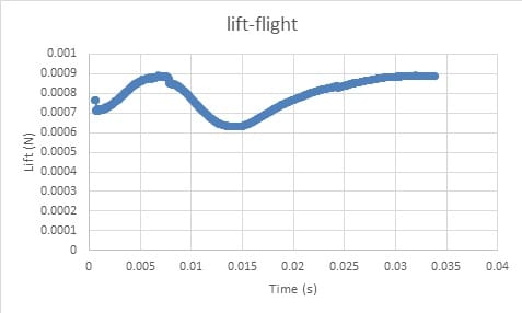
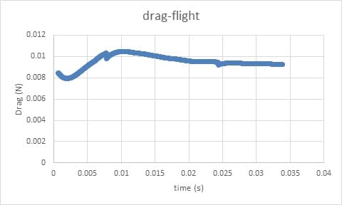
- We study aerodynamic forces, including drag and lift.
Click on Add To Cart and obtain the Geometry file, Mesh file, and a Comprehensive ANSYS Fluent Training Video.
To Order Your Project or benefit from a CFD consultation, contact our experts via email ([email protected]), online support tab, or WhatsApp at +44 7443 197273.
There are some Free Products to check our service quality.
If you want the training video in another language instead of English, ask it via [email protected] after you buy the product.
Description
Description
A propulsion is a device that converts mechanical force into thrust in aircraft and ships. The movement of air or water provides the necessary thrust. A propeller consists of two or more twisted blades. When the propeller rotates around its axis, the lift produced by these blades moves the air in a horizontal direction.
In advanced systems, the propellers are responsible for converting the rotational power of the engine crankshaft (piston engines) into propulsion. This force is equal to the product of the mass of air pushed back by the propeller per second and the velocity given to the airflow.
If a person is standing on the ground behind a rotating propeller while the aircraft is stationary, he can fully feel the airflow. In principle, the propeller blade is like a small wing that produces aerodynamic force.
This aerodynamic force can be broken down into one component of the force along the axis of the aircraft (propulsion force) and another component in the propeller blade plate (torque force).
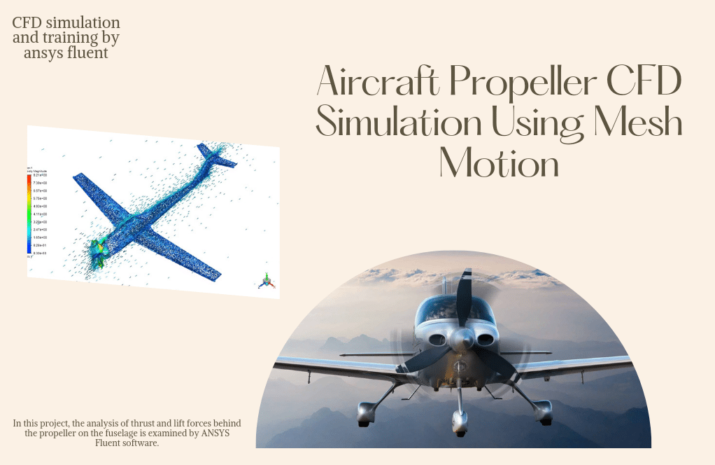
In this project, the analysis of thrust and lift forces behind the propeller on the fuselage is examined by ANSYS Fluent software.
First, the geometry of the plane and the propeller in Solidworks software are designed and modeled to create the mesh, create the grid, and name the boundary conditions.
The geometry file is implemented in ANSYS Meshing software. The mesh is carried out in ANSYS Meshing software. The elements are first used as tetrahedral and then polyhedral mesh Fluent, which has fewer cells and better quality.
The element number equals 3812519 for tetrahedral and 692023 for polyhedral mesh type.
Aircraft Methodology
Aircraft and propeller modeling is performed in two zones, rotational and stationary. Using the Mesh Motion method, the computational domain must rotate around the impeller axis to model the impeller rotational motion.
Due to the greater importance of the impeller in the problem results, it is preferable to mesh around it with more refined elements. The cylindrical computational domain around the impeller with a value of 1.12 impeller diameter is considered, and in that area, the meshing is done more accurately.
The rotational domain is located inside the fixed zone and is separated using an interface that transfers values between these two domains. Also, the solver is Transient.
Scaling analysis for rotational impeller simulation is such that the number of advanced coefficients must be paid for in this modeling. According to the table below, the advanced coefficient is based on the relationships used for similar samples.
Tip Speed Ratio (TSR) = 1/ J = V/(n*d)
D: impeller diameter = 0.0532 m
n: impeller speed = 1800 rpm = 30 rad/s
As a result, for J = 1.225, the flow velocity is calculated at 2 m/s.
According to the calculations performed, these boundary conditions can be used to simulate different propeller scales.
Aircraft Conclusion
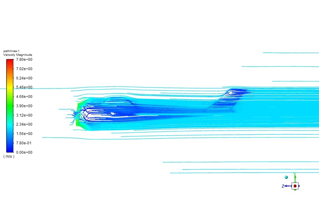
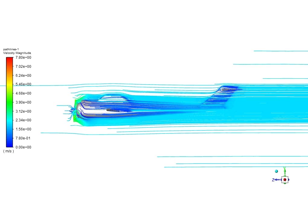
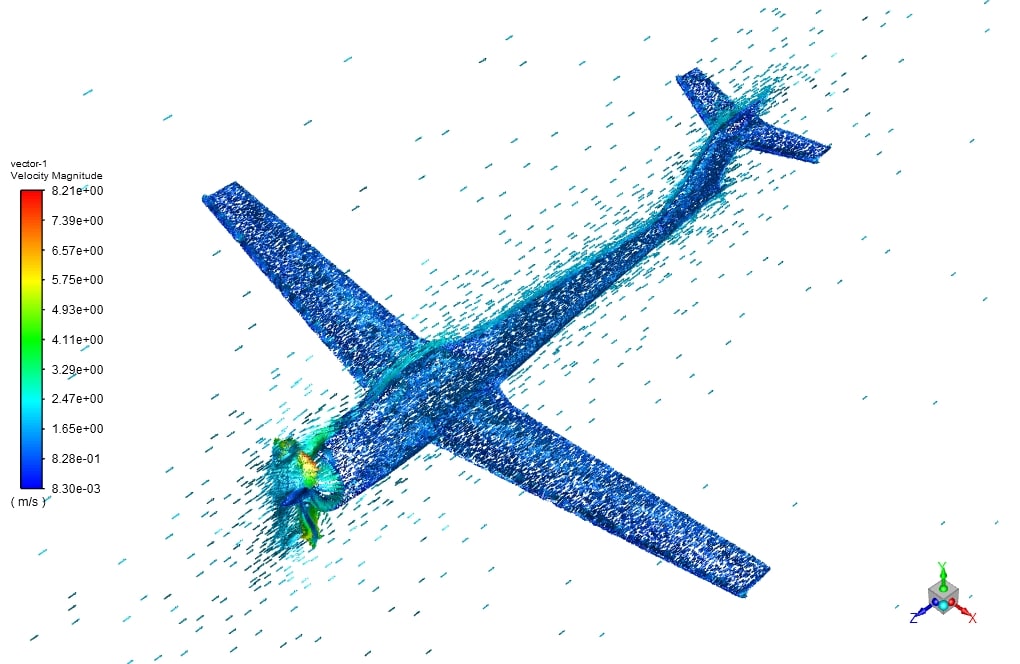
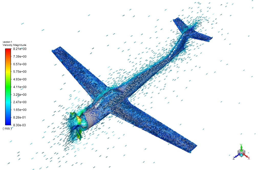
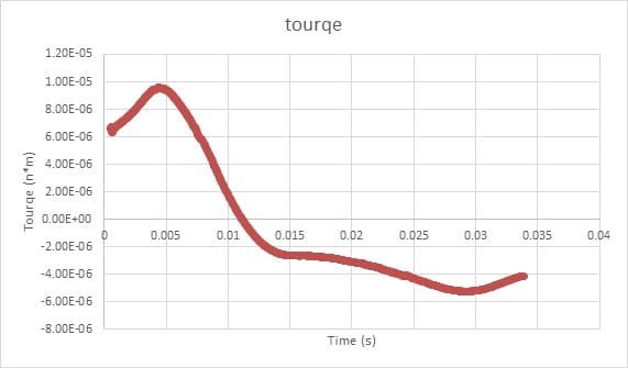
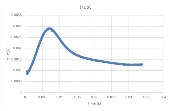
The results obtained from the simulation of lift and drag values for the fuselage are also the thrust and torque values for the propeller, which are shown in the following diagrams.
In the present work, simulations have been performed around the plane and the propeller, and the values of drag and lift force on the fuselage and thrust and torque on the impeller have been obtained.
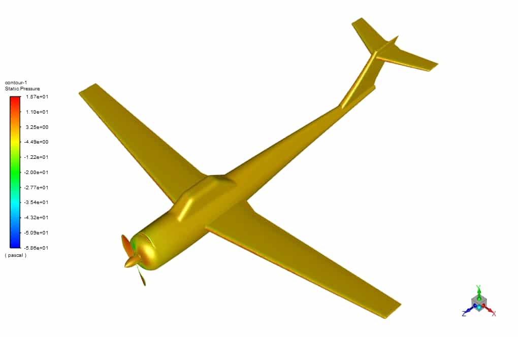
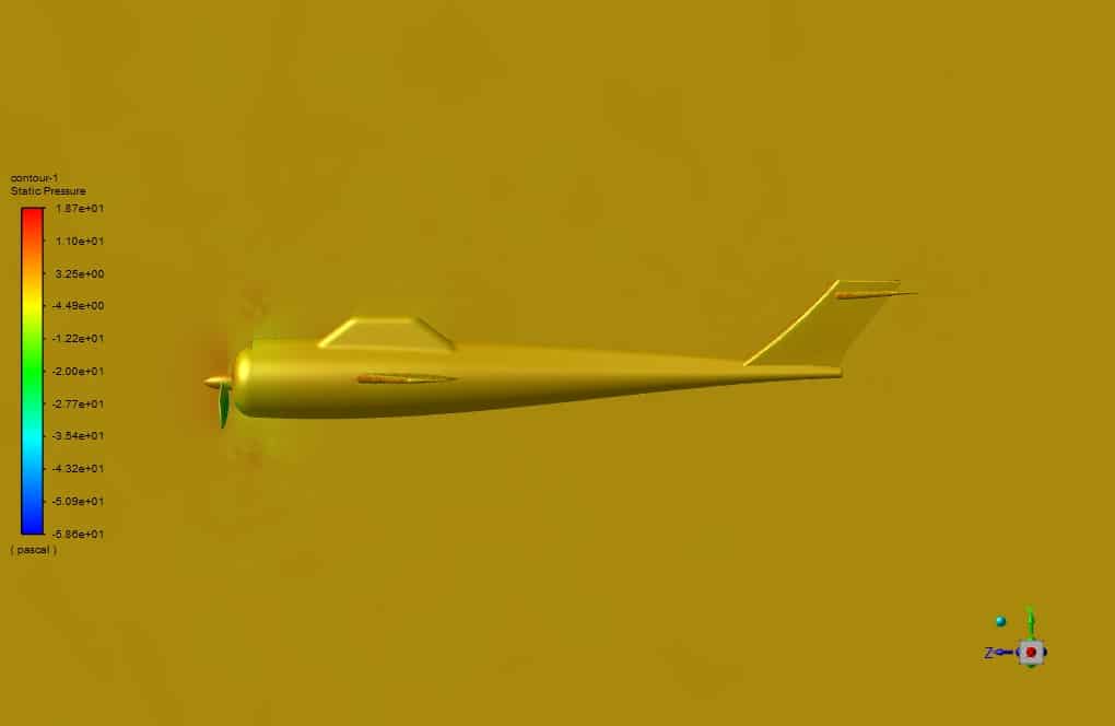
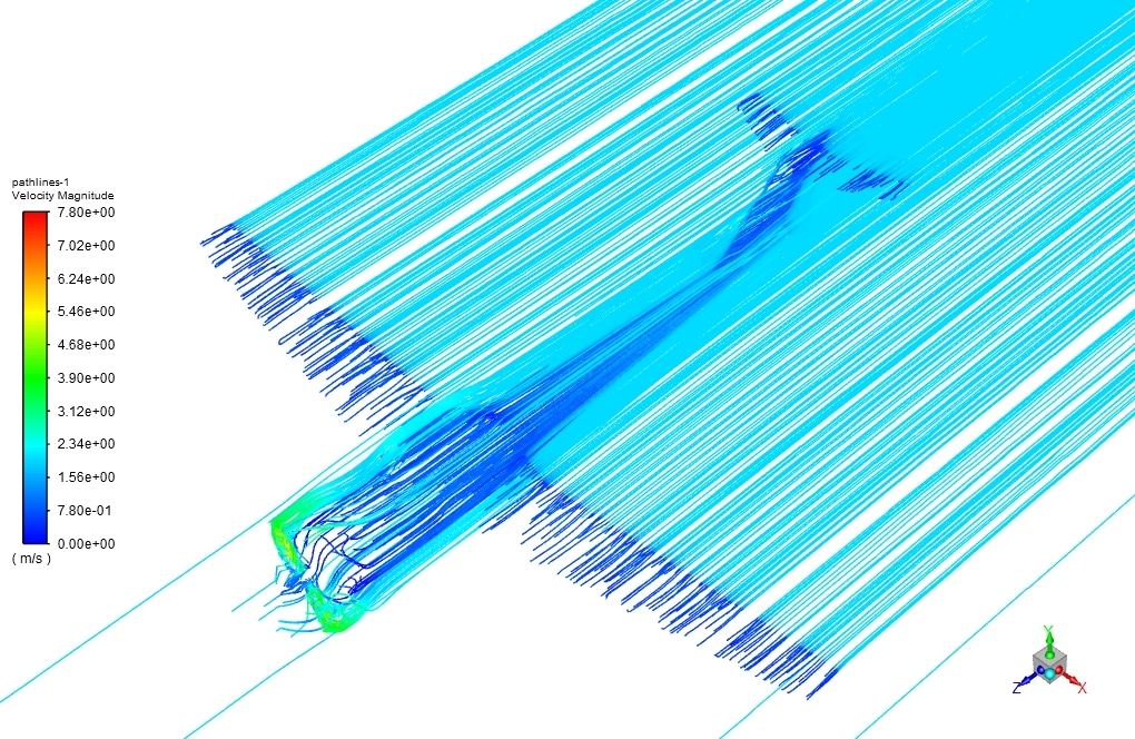
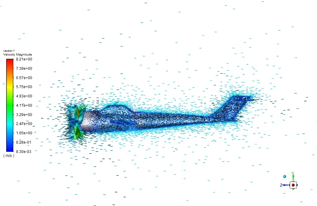
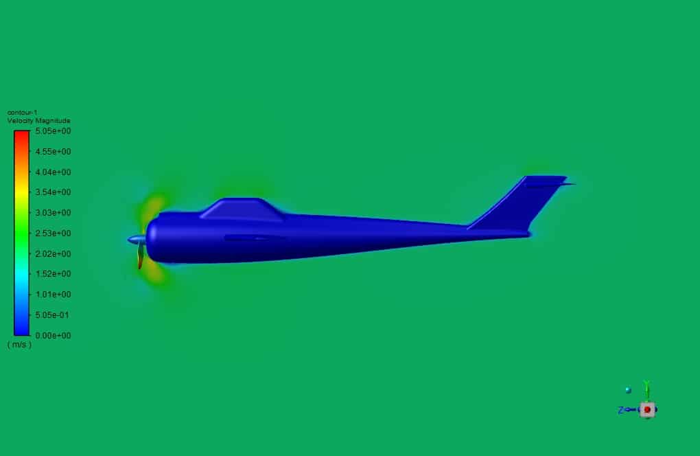
Also, the contours, vectors, and flow lines represent the flow physics formed around this. This modeling showed that by observing the advance ratio for each propeller, working points could be defined as the relationship between flow velocity and propeller rotational speed.
But more specifically, we need more criteria to have an entirely correct simulation, such as the Reynolds number based on the impeller speed and flow velocity.
From experimental studies and previous work, it can be seen that to simulate rotating impellers, and it is necessary to use the Advance Ratio criterion with the propeller speed and velocity values in terms of the criteria of the two Reynolds numbers mentioned above.
For a similar propeller, it is valid that the Reynolds calculated with these numbers be larger than the critical Reynolds for that particular propeller. In this case, it can model and simulate aircraft and propellers based on the advanced ratio of real work points.



Kira Gulgowski –
The entire training seems comprehensive. One question: How are the results of the thrust and torque on the propeller extracted in ANSYS Fluent?
MR CFD Support –
In ANSYS Fluent, the thrust and torque on the propeller are calculated based on the force distributions throughout the rotating domain. The simulations incorporate the pressure forces as well as the tangential and radial components due to the rotation. The results are typically extracted from the simulation by integrating these force components over the surface of the propeller in the rotational domain.
Miss Myrtis Gleason V –
The detailed presentation of the propeller analysis was excellent. Your application of mesh motion and analysis of aerodynamic forces were particularly insightful.
MR CFD Support –
We’re thrilled to hear that you found the propeller analysis insightful and that our presentation met your expectations. We always strive to provide thorough details and apply accurate techniques. Your feedback motivates our team to continue delivering high-quality CFD training. Thank you so much for your kind words!
Opal O’Hara –
The detailed explanation of the simulation and your comprehensive conclusion is truly helpful. Is it possible to adjust the rotational speed of the propeller within the simulation for different analyses, and would that affect the mesh motion setup significantly?
MR CFD Support –
Thank you for your positive feedback! Yes, you can adjust the rotational speed of the propeller to analyze different scenarios. However, this may require a review of the mesh quality to ensure it can tolerate the changes in the boundary layer and potential increase in the transient characteristics of the flow. If significant changes occur at different rotations per minute (rpm), you may need to refine the mesh or adjust the mesh motion settings accordingly.
Anabel Kiehn –
After studying the training, I have a deeper appreciation of the CFD analysis of aircraft propellers using ANSYS Fluent. The detail on mesh motion and transient solver explanations were exceptional. Applying the Advanced Coefficient and Tip Speed Ratio in simulations is indeed an eye-opener for optimizing design and performance.
MR CFD Support –
Thank you for your flattering feedback! We’re thrilled that we could provide you with valuable insights on aircraft propeller simulation using ANSYS Fluent. It’s gratifying to know that the Mesh Motion and TSR applications were particularly useful for you. We’re always here to help with any further questions you might have on CFD analysis and optimization using our training materials.
Mrs. Lolita Gusikowski –
I enjoyed learning from the Aircraft Propeller CFD Simulation course and appreciate the combination of practical examples along with the theory. There was a great deal of information to absorb, and I was wondering if there’s a guideline on how to validate the CFD model against real-world experimental data or if a particular validation case study was included as a part of the training material.
MR CFD Support –
Thank you for your review. Validation of CFD models is a crucial step, and as part of our course content, we provide methodology on comparing simulation results with empirical or experimental data. Although we include the theory for validation processes, specific case studies may vary. If you need resources for a particular case study or validation guidelines tailored to your project, our team is available to assist and guide you further to ensure your model is accurate and reliable.
Mervin Padberg –
I recently completed the ‘Aircraft Propeller CFD Simulation Using Mesh Motion’ training, and the depth of detail was impressive. I now have a solid understanding of how to set up my own simulations, including the intricacies of meshing and defining appropriate boundary conditions. The sections on thrust and lift forces were particularly illuminating. Thank you for an in-depth and thorough CFD training product.
MR CFD Support –
We truly appreciate your positive feedback on the Aircraft Propeller CFD Simulation training. It’s great to hear that you found the content informative and that it helped you gain a solid understanding of simulation setup. Thank you for choosing MR CFD Company’s learning products, and we hope to continue providing you with in-depth studies for all your CFD needs!