Laminar Flow Heat Transfer in U-Bend, Paper Validation
Free
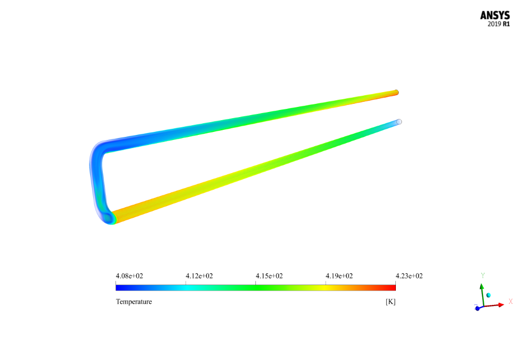
- The problem numerically simulates Laminar Flow and Heat Transfer in U-Bend using ANSYS Fluent software.
- We design the 3-D model with the Design Modeler software.
- We Mesh the model with ANSYS Meshing software, and the element number equals 2268000.
- This project is simulated and validated with a reference article.
To Order Your Project or benefit from a CFD consultation, contact our experts via email ([email protected]), online support tab, or WhatsApp at +44 7443 197273.
There are some Free Products to check our service quality.
If you want the training video in another language instead of English, ask it via [email protected] after you buy the product.
Description
Laminar Flow and Heat Transfer in U-Bend, Paper Numerical Validation, CFD Simulation by ANSYS Fluent
The present problem simulates the fluid flow inside a tube with a U-shaped bend by ANSYS Fluent software. The simulation was performed and validated according to the reference article “Laminar flow and heat transfer in U-bends: The effect of secondary flows in ducts with partial and full curvature.”
The fluid defined inside the tube was therminol; Its properties include density equal to 793.9 kg/m3, specific heat capacity equal to 2315 j/kg.K, thermal conductivity equal to 0.116 W/m.K and viscosity equal to 0.00173 kg/m.s.
According to the paper, the simulation has been done in different Reynolds numbers. The present simulation has been done in Reynolds number 1000. According to the formula related to the Reynolds number in the paper, the inlet velocity in the pipe is equal to 0.21791 m/s.
The present 3-D model is drawn using Design Modeler software. This model consists of a tube consisting of a bend. This bend is in the form of two knees connected. The pipe diameter is 0.01m, and the radius of curvature of each elbow is 0.015m.
The meshing has been done using ANSYS Meshing software, and the mesh type is structured. The element number is 2,268,000.
U-bend Methodology
In this model, the thermal boundary condition on the pipe wall is used; So that a constant heat flux of 1156 W/m2.K is defined on the pipe wall.
U-bend Conclusion
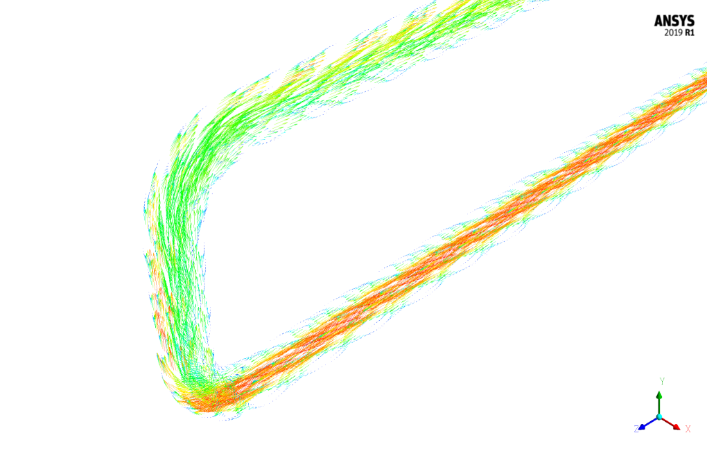
The purpose of the present problem is to investigate the behavior of the flowing fluid in the pipe and its heat transfer in the passage through the pipe bend. At the end of the solution process, the results are compared and validated with the results of the reference article.
First, the results related to the amount of fluid temperature on the pipe’s inner wall and its bending are validated. This validation is performed according to the diagram in Figure 14-b of the article.
For this purpose, a graph of temperature changes in the position of the pipe’s inner wall is drawn. Temperature and position are dimensionless, and the related formulas are presented in the article. The following figure shows a graph of dimensionless temperature changes in dimensionless position.
Then the Nusselt number is investigated in different sections of pipe bending. For this purpose, the value of the Nusselt number, according to the formula in the article, in five different sections (P1, P2, P3, P4, and P5) has been obtained, and its ratio to the value of the Nusselt number in section P1 has been calculated.
These resulting numbers are validated with the values of the dimensionless Nusselt number in the mentioned sections according to the diagram in Figure 19-b. The following table shows the values of the Nusselt number ratio at different sections of the pipe bend.


Ludwig Runte MD –
This product helped me understand the dynamics of laminar flow in curved pipes. Would you recommend using the same settings for other similar studies with different fluids?
MR CFD Support –
We’re glad that you found the simulation useful for understanding laminar flow in curved pipes. For studies with different fluids, please note that while the methodological approach remains similar, you will need to adjust the properties such as density, specific heat capacity, thermal conductivity, and viscosity according to the new fluid to obtain accurate results. Additionally, inlet velocity and heat flux should correspond to the specifics of the new study as well.
Evelyn Botsford Jr. –
This product is simply outstanding! I’ve been fascinated by the depth at which the U-Bend’s flow and heat transfer analysis dove into. With the meticulous validation against literature, it’s impressive how the simulation outcomes align with the established data. Using structured meshes clearly contributed to the precision, and I’m particularly interested in the critical role of the secondary flows in shaping heat transfer patterns. Hats off to the team’s effort in presenting such complex phenomena in an accessible manner.
MR CFD Support –
Thank you for your kind words! We are thrilled to hear about your positive experience with our Laminar Flow Heat Transfer in U-Bend simulation. Our team works diligently to ensure accuracy and relevance by meticulously validating our simulations, and it’s rewarding to know when these efforts resonate with our users. Your interest in the nuances of secondary flows and their effects is much appreciated, as we aim to uncover and present these intricate details. We’re looking forward to offering you more valuable insights with our future products. Thank you for choosing MR CFD Company.
Darius Bruen –
The product description lays out a clear methodology for analyzing laminar flow and heat transfer in a U-bend tube. Based off the detailed validation with the paper, it seems comprehensive. However, if I already have data on temperature distributions and Nusselt number variations at various sections of the pipe from experiments, can I use this product to match and compare with my experimental data?
MR CFD Support –
Absolutely, the simulation process in this product is designed to compare numerical results with experimental or theoretical data. You can match your experimental temperature distributions and Nusselt number variations with the simulation results provided by this CFD product. It is an excellent opportunity to validate and ensure the accuracy of your experimental setup and to understand the deviances if there are any.
Litzy Goodwin –
I’m particularly impressed by the attention to detail in your simulation settings to closely match the paper’s specifications. The use of structured meshing shows a deliberate choice to capture detailed flow behavior within the U-bend. Great job!
MR CFD Support –
Thank you for your kind words! We always strive to provide accurately detailed simulations to our customers and ensure the results are as close to reality as possible. Your appreciation motivates us to continue delivering high-quality CFD simulations.
Ed Trantow DVM –
I was impressed by the detail and validation approach in the U-Bend simulation description. The specificity in the parameters and methodology provides great assurance in the accuracy of the results. It’s clear there was meticulous attention paid to replicating the conditions from the reference article.
MR CFD Support –
Thank you for your appreciative feedback! We take pride in our thorough validation process and are glad to hear that our dedication to accuracy meets your expectations. Your satisfaction is a great source of motivation for us.
Dr. Laisha Nienow IV –
From this course, I learned so much about setting up intricate simulations! Seeing the methodology applied from theoretical papers to tangible results in Fluent has been invaluable. The clear explanation of verification with rheological data from benchmarks adds to the value. Great stuff!
MR CFD Support –
We are thrilled to hear that you found the course insightful and practically beneficial! It’s our core mission to ensure that the theoretical aspects of simulations are well interpreted into Fluent software applications. Your appreciation motivates us to continue delivering high-quality educational content. Thank you for your wonderful review!
Clay Stroman –
I’m fascinated by how the U-bend affects thermal flow characteristics. Could you please elaborate on how the secondary flows influenced the heat transfer in this simulation?
MR CFD Support –
In this simulation, secondary flows induced by the curvature of the U-bend played a key role in enhancing heat transfer. These secondary flows create a swirling motion perpendicular to the primary flow direction, leading to an increase in fluid mixing. This, in turn, improves the heat transfer efficiency, as evidenced by the variation in the Nusselt number across different sections of the U-bend. The swirling motion helps to break thermal layers and increase conduction at the pipe wall, ensuring a more uniform temperature distribution and higher rates of heat transfer.
Norma Runolfsdottir –
The U-bend model simulation seems incredibly comprehensive. I am curious to know how the results you obtained compare with the validation results from the reference article, specifically regarding the dimensionless temperature and Nusselt number distributions.
MR CFD Support –
Thank you for your interest! The simulation results showed good agreement with the data from the reference article. The dimensionless temperature and Nusselt number distributions matched closely with reported values, confirming the accuracy of the CFD model and simulation process in representing the actual physical phenomena.
Brooklyn Keeling –
This CFD simulation of laminar flow and heat transfer is quite intriguing! Could you share some insights on the primary challenges faced during the post-processing of simulation data for validation purposes?
MR CFD Support –
Thank you for your kind words! Typically, the central challenge in post-processing simulation data for validation is ensuring the accuracy of the results, especially when simulating complex flow patterns and temperature profiles in U-Bend tubes. It involves meticulous comparison of simulation data with experimental or theoretical results, careful calculation of dimensionless parameters like the Nusselt number, and generating precise graphs and tables to depict the findings. The structured mesh also plays a critical role, as an adequately refined grid ensures the capturing of gradients precisely to mirror the article’s benchmarks. Ensuring robustness in the simulation setup and the post-processing steps is crucial for a successful validation process.
Estrella Will –
I’m impressed with the thoroughness of the validation work done on this U-bend laminar flow simulation. Can the simulation results accurately predict real-life scenarios in similar designs?
MR CFD Support –
Thank you for your appreciation of this simulator’s attention to detail! The simulation results for the U-bend have been carefully validated against theoretical models and are designed to closely predict real-life thermal and fluid behavior in similarly designed systems, following the precise conditions examined.
Saige Mante –
The detailed insights into the fluid dynamics and heat transfer within the U-bend were absolutely captivating! The thorough method following the paper’s validation and the impressive convergence of the simulations generated truly robust and credible results. Having the physical temperatures and Nusselt numbers, backed by the charts and graphs, gave a great degree of confidence in the numerical model’s precision. Well done MR CFD on an intricate job executed to near perfection!
MR CFD Support –
Thank you so much for your positive feedback! We are delighted to hear that you are satisfied with the accuracy and detail of our CFD simulation for the Laminar Flow Heat Transfer in U-Bend. Our team strives to provide precise and credible results, and it’s rewarding to know that our efforts are recognized and appreciated. If you have any more questions or need further assistance with our products, please don’t hesitate to reach out.
Deanna Bashirian Sr. –
This CFD product’s validation with academic literature gives so much confidence in its results. The detailed explanation of the methodology and conclusions offers a clear understanding of the process.
MR CFD Support –
Thank you for your positive feedback! We are glad to hear that our comprehensive validation process and attention to detail meet your expectations and provide you with confidence in our CFD simulation results.
Ethyl Lowe III –
The simulation materials and setups are very intricate and precise. The thorough validation process demonstrates confidence in the accuracy of the results.
MR CFD Support –
Thank you so much for your kind words! We’re thrilled to hear that you appreciated the careful setup and validation within the simulation. Ensuring accuracy and relaying confidence in our results is a top priority for us. If you ever have further questions or need assistance with our products, don’t hesitate to reach out.
Orville Kuhic –
I was quite impressed by the in-depth simulation that MR CFD managed in their study on Laminar Flow and Heat Transfer in U-Bend. The adherence to the specified parameters, such as therminol fluid properties, and the structured approach in reaching different Reynolds numbers showcases their expertise. The detailed comparison to the documented research shows a responsible and scientific methodology that deserves praise.
MR CFD Support –
Thank you for recognizing the diligent work and attention to detail that went into our study on Laminar Flow and Heat Transfer in U-Bend. It’s immensely gratifying to hear that the efforts in meticulously following the given parameters and in validating the Reynolds numbers were well-received. Your appreciation underscores the value we place on scientific accuracy and integrity in our simulations.
Mrs. Trinity Waters IV –
This CFD simulation mimics fluid flow in a U-bend very well. Using ANSYS Fluent for such complex tasks shows how capable it is. Great job on the meshing and the structured approach taken, ensuring results align with the referenced paper. The use of dimensionless temperature and Nusselt number analysis is impressive, adding to the paper’s credibility. I commend your hard work and dedication to achieving such accurate validation.
MR CFD Support –
Thank you for your positive feedback! We strive to ensure that our CFD simulations are not only accurate but also provide in-depth analysis, replicating complex real-world scenarios. Your recognition of the mesh quality and our structured methodology is much appreciated. We always aim for our simulations to serve as valuable benchmarks and educational resources.
Mr. Ola West –
Just blown away by the level of detail in this study—validate a complex flow like laminar heat transfer in a U-bend based on a technical paper is no easy feat. Kudos to the MR CFD team for their rigorous work and for providing such precise results that stick closely to published data!
MR CFD Support –
Thank you for your kind words and appreciation! We are thrilled to hear that the detail and accuracy of our laminar flow heat transfer in a U-bend simulation met your expectations. We strive to provide the most reliable and extensively validated CFD studies, and we’re glad to see these efforts resonate with our customers.
Asha Considine –
The results seem quite comprehensive! Is this training also suitable for those who are new to CFD analysis, or is it oriented towards experienced users?
MR CFD Support –
Glad to hear you find the results comprehensive! This training is designed to be accessible for beginners as it’s intended to walk users through the process of simulation step-by-step, but it’s also detailed enough for experienced users looking for a specific application like U-Bend simulations for laminar flow heat transfer validation.
Dr. Manuela Muller DVM –
I was impressed with the thorough validation process comparing the simulation results to reference papers. I am curious, however, about how changes in the Reynolds number would affect the heat transfer and flow characteristics in the U-bend simulation.
MR CFD Support –
Indeed, the influence of the Reynolds number on both flow and heat transfer within a U-bend is significant. As you may know, the Reynolds number is a dimensionless quantity that characterizes the flow regime—laminar or turbulent. With a higher Reynolds number indicating more inertial forces compared to viscous forces; which means that with increasing the Reynolds number, you can expect the development of more complex flow characteristics, an increase in mixing within the fluid, and potentially enhanced heat transfer due to turbulence. However, each flow configuration might have nuances, so specific responses can vary based on geometry and boundary conditions.