
Baffle Cut Effect on Shell and Tube Heat Exchanger
$100.00 Internship
In this project, to investigate conjugated heat transfer, the heat exchanger of shell and tube with metal baffles was modeled.
Click on Add To Cart and obtain the Geometry file, Mesh file, and a Comprehensive ANSYS Fluent Training Video.To Order Your Project or benefit from a CFD consultation, contact our experts via email (info@mr-cfd.com), online support tab, or WhatsApp at +44 7443 197273.
There are some Free Products to check our service quality.
If you want the training video in another language instead of English, ask it via info@mr-cfd.com after you buy the product.
Description
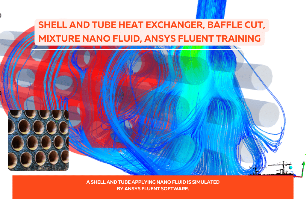
Baffle Cut Effect on Shell and Tube Heat Exchanger Efficiency, Conjugated Heat Transfer
Shell and tube heat exchangers are widely used in industry. The use of baffles (usually made of aluminum) and directing the flow of circulating fluid can create more heat distribution inside the shell by its high heat conduction and rise the total heat transfer rate. However, in the meantime, pressure drop should also be considered because enhancing thermal efficiency by increasing the number of baffles will lead to more pressure drop inside the heat exchanger. Therefore, it is necessary to pay attention to baffle cuts and the distance between them in the study of shell and tube heat exchangers.
Problem Description
In this project, Baffle Cut Effect on Shell and Tube Heat Exchanger efficiency to investigate conjugated heat transfer, with metal baffles was modeled. ANSYS Fluent software was used for the simulation. At the entrance to the shell, a cooler fluid, assumed to be water, flows at a temperature of 300 K and a flow rate of 0.5 kg / m3 (equivalent to a velocity of 0.7 m / s). The temperature of the inner tubes for cooling purposes was set at a constant wall temperature of 450 K. The material’s physical properties are defined as piecewise linear in the software. This study aimed to demonstrate the effect of the high thermal conductivity of baffles on better thermal distribution from hot tubes. The following figure shows the general specifications of the model along with the inlet and outlet of the problem.

Geometry & Mesh
The geometry was designed using the Design modeler module (figure below), and its geometric specifications include a shell with 600 mm distance and 90 mm in diameter, six baffles with a thickness of 4 mm, the center-to-center distance of the baffles was 86 mm, and the value of baffle cut was 36%. Also, seven tubes with an outer diameter of 20 mm with a triangular arrangement and a center-to-center distance were 30 mm inside the shell.

For grid generation, unstructured mesh with 1953754 elements and 30 mm element size in the ANSYS Meshing module was used. In addition, a boundary layer mesh was used near the walls to satisfy the Y-Plus number condition of the standard wall function. The following figure shows the mesh at different magnifications.

Baffle Cut Effect on Shell and Tube Heat Exchanger CFD Simulation Solver Setting
Fluent software was used to solve the governing equations numerically. Then, the problem is analyzed steadily, using the pressure-based method and considering the gravitational effects.
Material Properties
In this study, water fluid was used as the working fluid. Since the properties of water are defined as constants in the Fluent database, to improve the accuracy, they are redefined using piecewise-linear functions of temperature by using the ‘‘Thermo-Physical Properties of Saturated Water” tables available in the Thermodynamic books.

Boundary conditions & Solution methods for Baffle Cut Effect on Shell and Tube Heat Exchanger
Also, The table below shows the characteristics and values of boundary conditions, along with the models and hypotheses.
| Material Properties | |||
| Amount | Fluid properties (water) | ||
| piecewise linear | Density | ||
| piecewise linear | Specific heat | ||
| piecewise linear | Thermal conductivity | ||
| piecewise linear | viscosity | ||
| Boundary Condition | |||
| Type | Amount (units) | ||
| Mass flow inlet (water at 300 K) | 0.5 kg/m3 | ||
| pressure outlet (gauge pressure) | 0 pa | ||
| Shell wall | Adiabatic (heat flux=0 W/m2) | ||
| Tube wall | Constant temperature (450 K) | ||
| Cell zone condition | |||
| solid | fluid | ||
| baffles | water | ||
| Turbulence models (Shell&Tube) | |||
| K- | viscous model | ||
| realizable | K- model | ||
| Standard wall | Wall function | ||
| Solution methods ( Shell&Tube ) | |||
| Simple | pressure velocity coupling | ||
| standard | pressure | spatial discretization | |
| First-order upwind | momentum | ||
| First-order upwind | turbulent kinetic energy | ||
| First-order upwind | turbulent dissipation rate | ||
| First-order upwind | energy | ||
| Initialization | |||
| standard | initialization method | ||
| 0 (Pa) | gauge pressure | ||
| -0.7 m/s | y-velocity | ||
| 0 (m/s) | y-velocity, z-velocity | ||
Results
In this section, by examining the outlet temperature diagram of the shell, which is around 360 K, considering that the inlet temperature was 300 K, with the passage of hot fluid through the pipes, the water temperature increases by moving between the pipes.

Also, the values of heat transfer coefficient and total heat transfer rate converge with increasing iteration.


As can be seen in the results, by simultaneously modeling the baffles and the fluid flow and studying the problem from the perspective of conjugated heat transfer, it was found that temperature diffusion occurs much more quickly due to the presence of baffles, and this increases the average temperature of the fluid as much as possible. It is also proportional to the increase in heat transfer coefficient.
In addition, the total pressure contour at a plain in the middle of the heat exchanger shows that the amount of pressure drop is in the range of 1 kPa for this exchanger.
Reviews
You must be logged in to post a review.

Felicita Kautzer –
I had a question about the flow rate. You mentioned it as both 0.5 kg/m3 and 0.7 m/s. Is 0.5 kg/m3 the mass flow rate or the density?
MR CFD Support –
Thank you for reaching out. In the description, ‘0.5 kg/m3’ should refer to the density of the water at the inlet condition. The flow velocity is correctly described as ‘0.7 m/s’. In practical terms, the mass flow rate can be calculated by multiplying the density of the fluid by the velocity and the cross-sectional area where the fluid enters the heat exchanger.
Loyce Fahey –
This course was an eye-opener for optimizing baffle design in my shell and tube heat exchanger projects! I appreciated the detailed theory alongside practical software tips.
MR CFD Support –
Thank you for your positive feedback! We are thrilled to hear that you found the course tutorial on optimizing baffle design in shell and tube heat exchangers both informative and practically useful. Your satisfaction with the combination of theoretical foundations and hands-on software guidance is exactly what we aim for. If you have any more questions or need further assistance in your future projects, do not hesitate to reach out.
Annamae Mann –
Are there particular regions or patterns indicating higher efficiency or performance issues in this shell and tube heat exchanger model due to the baffle cut?
MR CFD Support –
The simulation results show improved heat transfer due to the increased surface contact delivered by the baffle cut setup. However, also expect to observe higher pressure drops around the baffles which might lead to performance considerations. One should look closely at the heat transfer coefficient and total heat transfer rate for signs of increased efficiency and examine the total pressure contours for potential issues related to pressure drops.
Destinee Quigley –
The learning kit truly delivers! Delightful to dive into the comprehensive simulation details and witness how baffle cut impacts efficiency in heat exchange. So impressed by the meticulous mesh representation and clear solution methodology. Well explained post-process results too!
MR CFD Support –
Thank you for the kind words and for recognizing the effort put into our learning kit on the Baffle Cut Effect on Shell and Tube Heat Exchanger. We take great pride in delivering detailed and clear simulations. Your satisfaction is very important to us and we’re thrilled that you found the content insightful. We hope it augments your understanding and skills in CFD.
Ms. Delta Swift PhD –
This is an incredibly useful study for understanding baffle configuration in heat exchangers. Can you explain if different baffle cuts have different effects on pressure drops?
MR CFD Support –
Yes, indeed, different baffle cuts have impacts on pressure drops within the shell and tube heat exchanger. Varying the cut size alters the flow path and can change turbulence and velocity profiles; increasing baffle cut generally decreases pressure drop, improving flow but possibly at the expense of thermal performance.
Emil Prosacco –
What measures have been taken in the simulation to reduce the computational cost without sacrificing accuracy?
MR CFD Support –
The simulation employs strategies like defining piecewise linear functions for water properties, applying a standard wall function near the walls to satisfy the Y-Plus number condition, and using a steady-state solver instead of a transient one to contain computational demands. Pre-defining water properties and utilizing a standard wall function help ensure accurate boundary layers without excessive mesh refinement.
Ms. Isabel Bosco Jr. –
The review is brilliantly detailed and insightful! It provides comprehensive information about how baffle cut influences efficiency and pressure drop in shell and tube heat exchangers. Really appreciated the technical depth and the clarity in your explanation.
MR CFD Support –
Thank you so much for your positive review! We are thrilled to hear that you found the information detailed and insightful. It’s wonderful to know the depth and clarity of the explanation met your expectations. Your feedback is greatly appreciated, and we look forward to providing more high-quality products and resources in the future!
Ray Schmidt –
The information about the Baffle Cut effect on Heat Exchanger efficiency was comprehensive! Makes it easier for me to understand the importance of carefully designing the heat exchanger for better thermal distribution while managing pressure drop. So pleased with my learning experience!
MR CFD Support –
Thank you so much for your positive review! We’re delighted to learn that our product helped enhance your understanding of heat exchanger efficiency and the impact of baffle design. Your satisfaction with the learning experience is our top priority. If you ever have further inquiries or need more assistance with our learning products, please do not hesitate to reach out. Thank you for choosing our educational content, and we look forward to continuing to support your learning journey!
Maiya Dicki –
I found the explanation of the baffle cut effect on the efficiency of a heat exchanger very intriguing. I wonder how the pressure drop changes if the baffle cut size is reduced?
MR CFD Support –
In the context of this study, if the baffle cut size is reduced, the flow path for the fluid becomes narrower which typically results in an increased velocity through the gaps. This increment in velocity augment the pressure drop across the baffles due to increased frictional losses. The extent of this effect would depend on the specific geometric changes and the resultant flow dynamics.
Ena Torphy –
I’m highly impressed by the level of detail in your study regarding the Baffle Cut Effect on Shell and Tube Heat Exchanger! Kudos on a comprehensive simulation job that takes into account not only efficiency but also pressure drop concerns. I can see that a lot of thought has gone into finding the right balance through careful examination of baffle cuts and spacings. Your geometrical and solver settings are a testament to the thorough analysis underlying this project. Can’t wait to see how this informs better heat exchanger designs!
MR CFD Support –
Thank you for your positive feedback! We’re thrilled to hear that you appreciate the attention to detail and the depth of analysis in our Baffle Cut Effect on Shell and Tube Heat Exchanger simulation study. We strive to provide a comprehensive understanding of the system to help inform and improve heat exchanger design. Your enthusiasm for our work is truly motivating. If you have any further questions or need additional information, we’re more than happy to provide it. Thanks again for taking the time to review our product!
Aryanna Morissette –
I truly appreciate the comprehensive assessment on the impact of baffle cuts on heat exchange efficiency. It seems your study skillfully balances the trade-off between improved thermal performance and potential pressure drop increases. The integration of conjugated heat transfer analysis is particularly compelling, leading to more rapid temperature diffusion and a spike in thermal efficiency. Well done!
MR CFD Support –
Thank you for your kind review! We’re glad to hear you found the balance between heat transfer efficiency and pressure drop in the study of baffle cut effects on shell and tube heat exchangers to be well-demonstrated. We strive to provide detailed and accurate simulations and analyses, so your feedback is greatly appreciated. If you ever need further insights or have queries on our products, don’t hesitate to ask. Thank you for choosing us to aid in your understanding of thermal systems!
Keira Osinski –
This product has remarkably improved my understanding of how baffle design impacts heat exchanger performance. The detailed analysis of pressure drop in correlation with heat transfer efficiency has opened up new avenues for my project optimizations. A great learning resource indeed!
MR CFD Support –
Thank you for your positive feedback! We’re thrilled to hear that our product has assisted you in enhancing your project and understanding of heat exchanger dynamics. If you have further inquiries or need additional resources, feel free to reach out. Good luck with your ongoing projects!