Borehole Flow, ANSYS Fluent CFD Simulation Training
$80.00 Student Discount
The present problem simulates borehole water flow using ANSYS Fluent software.
Click on Add To Cart and obtain the Geometry file, Mesh file, and a Comprehensive ANSYS Fluent Training Video.To Order Your Project or benefit from a CFD consultation, contact our experts via email ([email protected]), online support tab, or WhatsApp at +44 7443 197273.
There are some Free Products to check our service quality.
If you want the training video in another language instead of English, ask it via [email protected] after you buy the product.
Description
Project Description
The present problem simulates borehole water flow using ANSYS Fluent software. Borehole or drilling is making a hole or drilling a well on the ground, which is used to identify the type of soil in the area. Pre-construction drilling or borehole is used to determine the soil type and groundwater status and agriculture and oil and gas drilling operations. A borehole is a hole of 5cm to 25cm in diameter that is drilled into the ground, and the exact size of this diameter depends on the type of soil under study. A borehole is a small-diameter well that is important in soil tests.
These boreholes can be drilled vertically, horizontally, or sloping and have an essential role in the industry to sampling soil materials, checking surface layers, sending equipment and tools, studying the soil condition of the area, etc. Now the water flow inside the borehole or well causes the soil grains to separate from the well wall and enter the water flow. Of course, the degree of separation of soil grains from the well wall depends on the grain’s diameter and the intensity of soil grain adhesion. Since this project simulates a mixture of water flow and soil grains, a multiphase flow must be defined. Therefore, the Eulerian multiphase model is used to determine the liquid-solid two-phase flow.
Project Description
So that the primary phase is water flow, and secondary phase is soil grain. In general, from the eulerian multiphase model in applications such as particle-laden flows with a volume fraction of more than 10% for the dispersed phase, or fluidized bed, or slurry flows including liquid and solid, is used. The calculation area is designed as a section of a well in the form of a vertical cylinder. The inner part of the domain is related to the area of water flow, and the outer part of the domain is related to the area of soil. Water flow with a speed of 1.6 m.s-1 along with soil particles with a velocity of 1 m.s-1 enter the central part of the well and affect the surrounding soil particles.
Borehole Geometry & Mesh
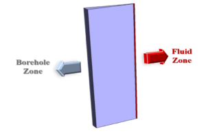
The present model is designed in three dimensions using Design Modeler software. It is assumed that the well is a perfectly symmetrical cylinder. Therefore, to reduce the computational cost, only one segment of this well has been modeled. This sector is composed of two separate sections in the radial direction. The inner or central part of the sector is related to the fluid flow area, and the outer part of the sector is related to the location of soil grains. Inlet and outlet boundaries are defined only for the water flow area in the central part of the model.
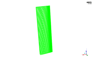
We carry out the model’s meshing using ANSYS Meshing software, and the mesh type is structured. The element number is 413658. The following figure shows the mesh.
Borehole Flow CFD Simulation
We consider several assumptions to simulate the present model:
- We perform a pressure-based solver.
- The simulation is unsteady.
- The gravity effect on the fluid is equal to -9.81 m.s-2 along the Z-axis.
The following table represents a summary of the defining steps of the problem and its solution:
| Models | ||
| Viscous | k-epsilon | |
| k-epsilon model | standard | |
| near wall treatment | standard wall functions | |
| turbulence multiphase model | dispersed | |
| Multiphase Model | Eulerian | |
| formulation | implicit | |
| number of eulerian phases | 2 (water & soil) | |
| Boundary conditions | ||
| Inlet | Velocity Inlet | |
| velocity magnitude – water | 1.6 m.s-1 | |
| velocity magnitude – soil | 1 m.s-1 | |
| Outlet | Outflow | |
| flow rate weighting | 1 | |
| Wall of Soil Zone & Fluid Zone | Wall | |
| wall motion | stationary wall | |
| Symmetry of Soil Zone & Fluid Zone | Symmetry | |
| Methods | ||
| Pressure-Velocity Coupling | Phase Coupled SIMPLE | |
| Pressure | PRESTO | |
| momentum | first order upwind | |
| turbulent kinetic energy | first order upwind | |
| turbulent dissipation rate | first order upwind | |
| volume fraction | first order upwind | |
| Initialization | ||
| Initialization methods | Standard | |
| gauge pressure | 0 Pascal | |
| velocity (x,y,z) for water | 0 m.s-1 | |
| soil volume fraction | 0 | |
| velocity (x,y,z) for soil | 0 m.s-1 | |
Results & Discussions
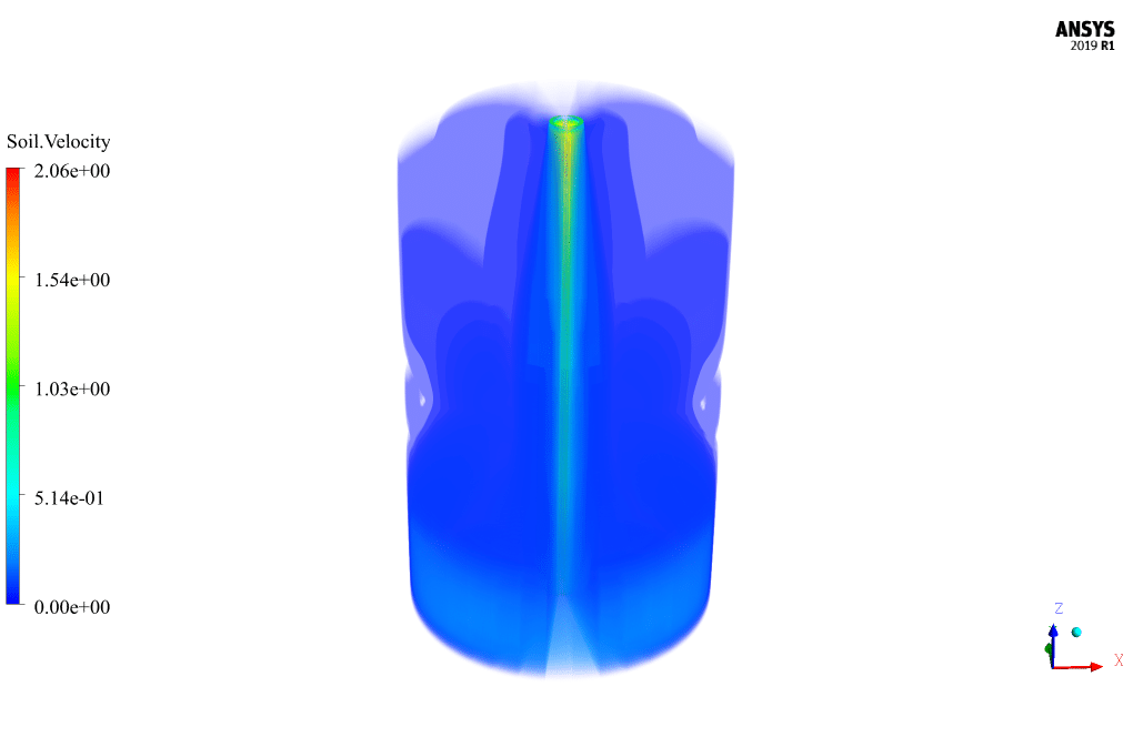
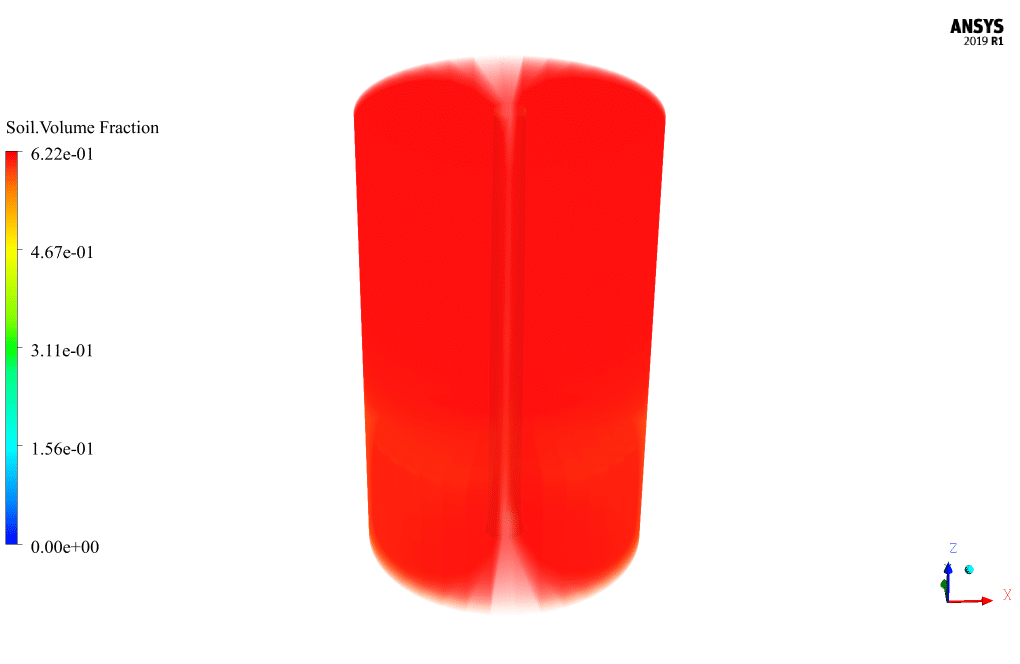
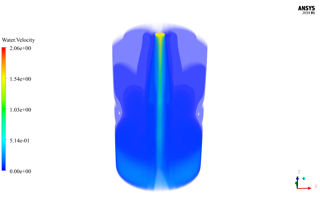
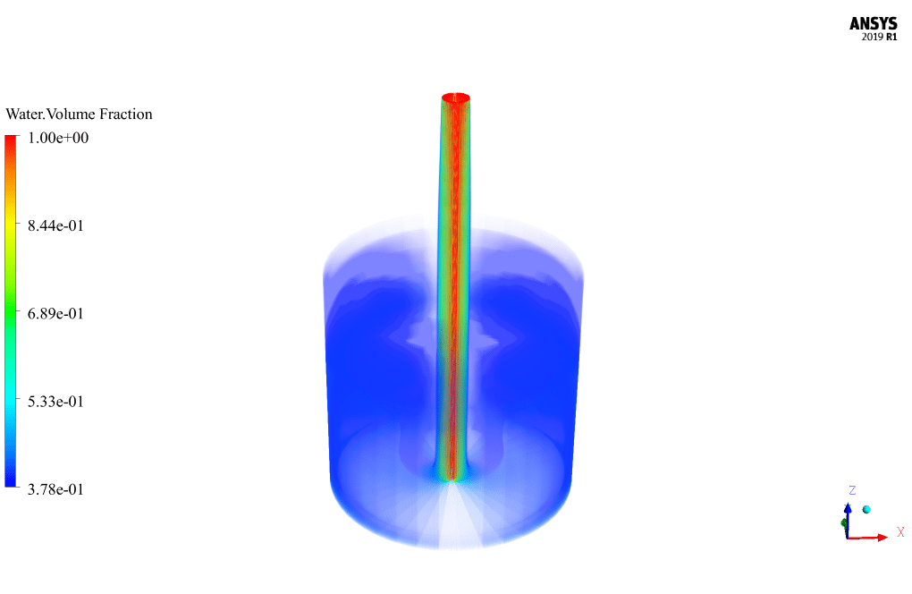
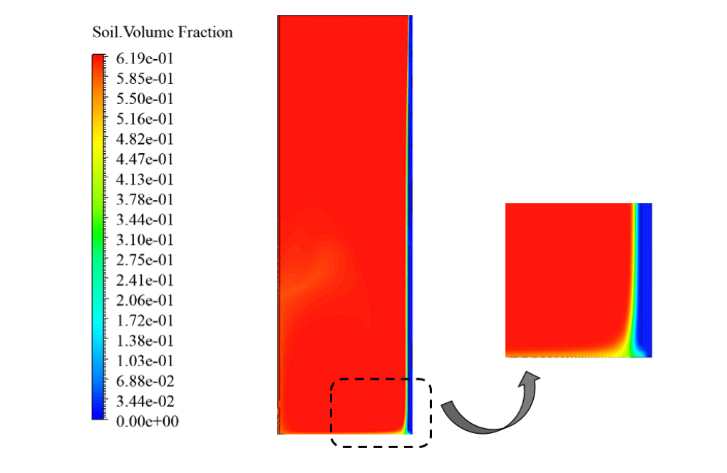
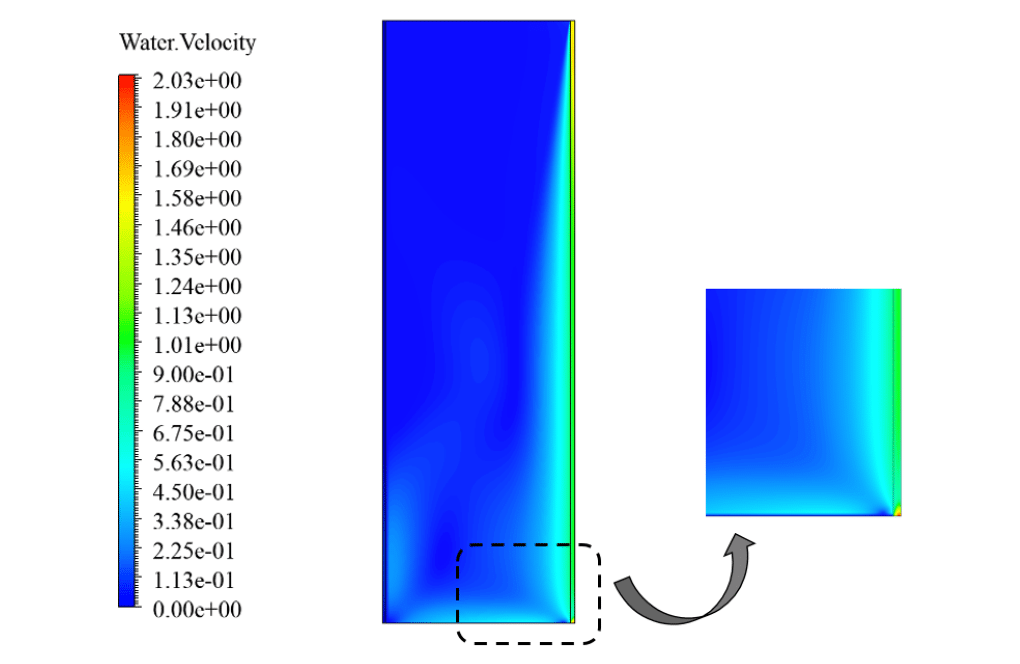
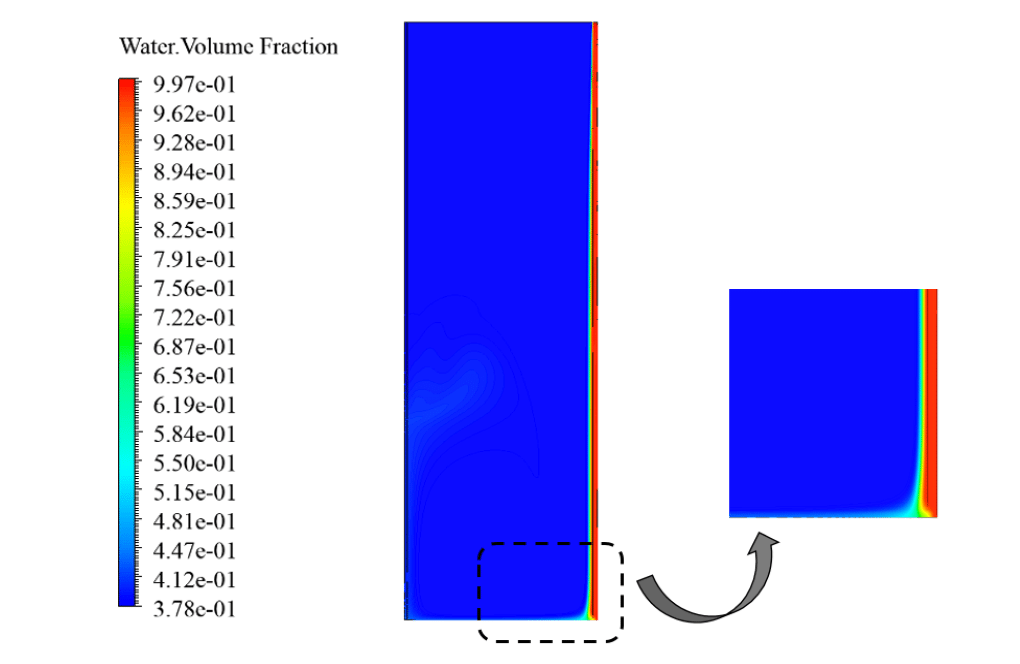
At the end of the solution process, we obtain two-dimensional contours related to the volume fraction and the velocity of water flow and soil particles. The results show that some soil particles are separated from the wall of the drilled well and join the water flow, and also some water flow penetrates the soil of the drilled well. This indicates that the amount of shear stress created between the water flow and soil particles prevails over adhesion between the soil grains.
Madelyn Botsford –
I am fascinated by the use of the Eulerian multiphase model here. Could you please explain how the soil’s adhesion properties are taken into account in the simulation? Does the model involve cohesion parameters for the soil particles, and how are they calibrated against real-world observations?
MR CFD Support –
In the simulation, the Eulerian multiphase model is used to account for the interaction between the fluid and solid particles. Adhesion properties and cohesion among soil particles typically require additional models or definitions within the simulation. However, such detailed information about calibration against real-world observations or specific cohesion parameters is not provided in the initial data. It is assumed that the soil grain separation is based on shear stress conditions of the flow which can indicate that a boundary interaction model may have been used. Details on calibrating such parameters would typically involve comparing simulation results to physical experiments or empirical data.
Rodrick Jacobs III –
The TP MODEL used in this simulation helps predict the behavior of water and soil particles accurately, leading to better planning in real-world drilling projects.
MR CFD Support –
We appreciate your positive feedback regarding the use of the Eulerian multiphase model in the Borehole Flow simulation. We are glad to hear that our CFD simulation training aided in the understanding of water and soil interaction, which is paramount in drill projects planning. Thank you for sharing your thoughts with us!
Liana D’Amore –
I’m curious, did the simulation address the possible re-deposition of soil particles along the borehole wall after detachment, which might affect the bore area or alter the water flow characteristics?
MR CFD Support –
The simulation focuses primarily on the initial detachment of soil particles due to water flow, using the Eulerian multiphase model for detailed analysis. While the re-deposition of particles may occur in a real-world scenario, this aspect is not explicitly mentioned in the provided simulation details. The simulation could be extended to study this phenomenon more profoundly if appropriate models and boundary conditions are incorporated to capture the particle-water interaction and settlement dynamics.
Chad Cummerata –
What a wonderful course on borehole flow simulation. I learned so much about soil mechanics relevent to my field work in soil test drilling. I found the in-depth explanation on usig ANSYS Fluent for modeling both water and soil grains with proper boundary conditions to be particularly useful.
MR CFD Support –
Thank you very much for your positive feedback! We are delighted to hear that our borehole flow simulation course met your needs and provided valuable insights into soil mechanics and CFD modeling in ANSYS Fluent. We strive to offer comprehensive training materials to help our customers excel in their fields. Should you have any more questions or need further assistance in the future, please do not hesitate to reach out. Happy drilling and analyzing!
Jared Wunsch Sr. –
The training has an impressive level of detail in the simulation! Could you explain how the choice of turbulence model influences the results of borehole flow simulations?
MR CFD Support –
Certainly! In borehole flow simulations, the choice of the turbulence model is vital because it impacts the accuracy of the predicted shear stresses and the interaction between the fluid flow and soil particles. The k-epsilon model, used in the simulation, is suitable for this case as it includes standard wall functions that adequately represent the near wall treatment, which is crucial when dealing with flows that have significant interactions with solid boundaries.
Dedric Brakus –
I’m struggling to understand the interaction between the water flow and soil particles. Can you clarify this further?
MR CFD Support –
The interaction between the water flow and soil particles in the simulation considers the shear stress created by the moving water as it interacts with the stationary soil grains. The soil particles are initially adhering to the well walls due to natural cohesive forces. However, as the high-velocity water flows through the borehole, it exerts shear stress on the soil grains. If this stress exceeds the forces keeping the grains attached to the well wall, they dislodge and get carried away by the water. This process of erosion is captured by the Eulerian multiphase model, illustrating how the separated particles are introduced into the flow due to the dynamics between the liquid (water) phase and the solid (soil) phase in the simulation.
Vernon Johns V –
I’m curious, how do simulation results assist in predicting the impact of real-world borehole operations on the surrounding soil environment?
MR CFD Support –
Simulation results provide insight into the dynamics between the water flow and soil particles within a borehole. They help to understand the magnitude of shear forces at play, predicting the likelihood of soil grain separation from the well walls. This information can be instrumental in devising construction strategies to minimize environmental disruption or determining the need for casings and other structural reinforcements in boreholes.
Petra Casper –
What practical application can this borehole flow simulation have in the construction industry? How could engineers utilize these results for real-world projects?
MR CFD Support –
The borehole flow simulation plays a crucial role in the construction industry. Engineers can use the simulation results to determine soil stability, predict groundwater impacts during construction, assess the risk of soil erosion, and plan for appropriate shoring or support structures needed for deep excavations. Additionally, this data helps in designing measures to mitigate potential issues related to underground water flow which may affect the foundation of structures.
Miss Effie Predovic –
What procedure was followed to ensure that the soil grain separation was authentically simulated?
MR CFD Support –
The simulation included the Eulerian multiphase model to represent the water and soil flow accurately. This ensures a realistic simulation of soil grain separation from the well wall by modeling the interaction between the fluid phase (water) and the solid phase (soil grains). The soil grains’ velocity at the entry point and the shear stress between the fluid and the soil due to the water flow were significant factors in achieving a credible simulation of the soil grain separation.
Vallie Lang –
The product helped me understand the factors governing borehole stability and erosion. The illustrations of soil particle separation and water penetration into the soil were particularly insightful. Great training material!
MR CFD Support –
We truly appreciate your positive feedback on our Borehole Flow ANSYS Fluent CFD Simulation Training. It’s wonderful to hear that the illustrations and material provided clarity on complex phenomena like borehole stability and soil erosion. Thank you for choosing our training, and we look forward to assisting you further in your learning journey!
Alexys Feest –
Very engaging simulation! However, I was wondering about the effects of particle size and density variations on the flow within the borehole. Are these factors accounted for in the simulation, and how do they influence the results?
MR CFD Support –
In the simulation, particle size and density are key parameters in predicting the behavior of the soil particles in the flow. These factors are taken into account in the Eulerian multiphase model. The simulation results reflect how variations in particle size and density affect the degree to which soil grains are eroded from the well walls and their transport within the water flow. Particles with different sizes and densities will have varying tendencies to be lifted and carried by the water flow, influencing the volume fraction and velocity profiles of both phases.
Prof. Ethel Ankunding –
I’m trying to understand how to predict the amount of soil that would detach and enter the borehole flow. Does the simulation provide a way to quantify this, or are there specific parameters I need to look at?
MR CFD Support –
The simulation you mentioned uses the Eulerian multiphase model to simulate the interaction between the borehole water flow and soil particles. To quantify the amount of soil that detaches and enters the water flow, you would need to examine the volume fraction and velocity contours of the soil particles. The soil volume fraction would give you an understanding of the concentration of soil particles within the flow, and areas of the well wall with higher soil particle velocity into the fluid likely indicate where detachment is occurring. Additionally, assessing the shear stress at the wall can help predict erosion rates.
Kassandra Miller PhD –
What specific mechanisms are used in the software to simulate the separation of soil grains from the well wall due to the water flow in this CFD project?
MR CFD Support –
To simulate the separation of soil grains from the well wall, the Eulerian multiphase model is utilized. The software calculates the interactions between the water flow and the soil particles, determining when shear stress from the water flow overcomes the adhesion of soil grains, allowing them to become dislodged and captured by the water flow.
Prof. Afton Dietrich –
I’m particularly interested in the separation of soil grains in the simulation. How were you able to tune the interaction between soil grains and water to model this phenomenon accurately?
MR CFD Support –
In this simulation, interactions between the soil grains and water were accurately captured using the Eulerian multiphase model, which allows for detailed calculation of interactions within a mixture. The model parameters, such as volume fractions and relative velocities between the phases, were fine-tuned to match the physical scenario of soil grains being influenced by water flow. Shear stress conditions and adhesion properties for the soil were calibrated based on empirical data to replicate the separation process realistically within the simulation.
Ms. Sasha Crooks –
I completed the Borehole Flow CFD Simulation training using ANSYS Fluent and was amazed by the quality of training provided. The step-by-step guidance helped me to understand the intricacies of simulating a borehole water flow, and the practical approach towards solving using the Eulerian multiphase model was particularly insightful. The lesson on setting various boundary conditions and interpreting the results has significantly boosted my confidence in handling similar multiphase flow challenges in my future projects.
MR CFD Support –
Thank you so much for your kind words! We’re thrilled to hear that you found the Borehole Flow CFD Simulation training valuable and that it’s given you more confidence in your CFD ventures. Our team works hard to ensure that our training is comprehensive and practical, so users like you can have a meaningful learning experience. Your success is a testament to our efforts, and we appreciate you taking the time to share your positive experience. If you ever have more questions or need further assistance, we are always here to help!
Alysa Waelchi –
I am exceedingly impressed with the detailed simulation of borehole water flow. The practical applications for soil sampling and studying groundwater conditions with this simulation are notable, and the use of the Eulerian multiphase model to represent the liquid-solid interaction seems particularly effective. Well done on achieving such a clear visualization of complex soil-water mechanics in the simulation.
MR CFD Support –
We appreciate your recognition of our work on the Borehole Flow simulation and your insightful remarks about the utility and complexity of the system. The effective use of the Eulerian multiphase model was crucial to accurately represent the liquid-solid interactions, and it’s rewarding to hear that the outcomes were both clear and useful. Thank you for your positive feedback.