Water Wheel CFD Simulation Training by ANSYS Fluent
$180.00 Student Discount
- The problem numerically simulates the Water Wheel (Pelton Wheel) using ANSYS Fluent software.
- We design the 3-D model by the Solidworks software.
- We Mesh the model by ANSYS Meshing software.
- We perform this simulation as unsteady (Transient).
- We use the Mesh Motion method model to define rotation movement.
To Order Your Project or benefit from a CFD consultation, contact our experts via email ([email protected]), online support tab, or WhatsApp at +44 7443 197273.
There are some Free Products to check our service quality.
If you want the training video in another language instead of English, ask it via [email protected] after you buy the product.
Description
Water Wheel (Pelton Wheel), ANSYS Fluent CFD Simulation Training
The present problem is Water Wheel CFD Simulation Training (Pelton Wheel) by ANSYS Fluent software. We perform this CFD project and investigate it by CFD analysis to analyse the performance.
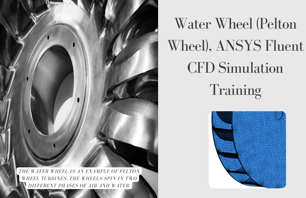
The water wheel is an example of a Pelton turbine. Most water wheels are mounted vertically on a horizontal axis and can also be mounted horizontally on a vertical shaft. In order to solve the fluid flow equations, the averaged form of the Navier-Stokes equation is used by applying ANSYS Fluent software.
The turbine’s diameter is 0.7 m, and the free surface’s boundary is 0.2 m below the center of the water wheel. Water velocity is considered 3 to 5 m / s depending on the average river velocity.
And accordingly, the turbine’s rotational speed should be calculated with no drag or bump in the flow. In this CFD simulation, the turbine rotational speed is 60 rpm.
Water Wheel Methodology
The wheels are perpendicular to certain turbine parts due to reduced friction force and increased nozzle thrust. The other part of the turbine is out of the water. Therefore, the wheels are in two different phases of water and air, rotating around their axis.
The two-phase model also uses the VOF model. We designed the geometry of the turbine by SOLIDWORKS and divided it into smaller sections to improve the geometry and mesh of the turbine.
We split the geometry into two general rotaries (Rotor) sections and one stationary unit (Stator). The rotor part consists of the turbine and the cylinder that is located around the turbine. The static part surrounds the rotary cylinder.
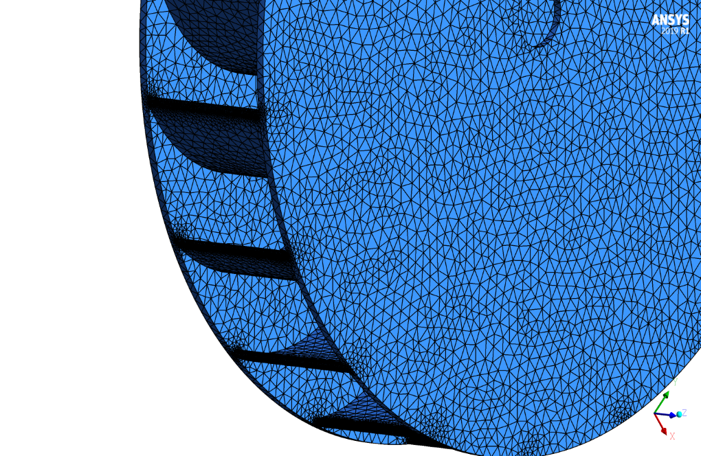
We use ICEM software to generate the mesh. The rotor section first meshes unstructured. Parts such as the turbine leading-edge use a larger number of meshes (smaller elements) due to the complexity of the flow and the high gradient in that area.
We use the structured mesh for the stationary zone. Structured mesh causes the number of mesh to decrease and the quality of the mesh to be very high. After meshing the two parts separately by two different methods, we couple the two parts together to mesh the total geometry.
The rotation of the impeller at each time step can have different values. In this simulation, we have 3 degrees of rotation of the impeller at each time step, which we should consider much smaller for more accurate simulations.
For the present issue, we should use the MESH MOTION. Static and rotary meshes slide with common boundaries (INTERFACE) and simulate the problem.
Water Wheel Conclusion
The results show well the rotational motion around the body of Pelton’s water wheel.

Bertha Spencer –
Can the simulation be adjusted to model different water wheel designs?
MR CFD Support –
Absolutely! The simulation is highly customizable and can be modified to accommodate a variety of water wheel designs.
Ms. Brandy Mann DVM –
How accurate is the power output prediction of this simulation?
MR CFD Support –
The simulation provides a highly accurate prediction of power output, thanks to its advanced numerical algorithms and realistic modelling of physical phenomena.
Bethany Block –
This training provided precise insights on the Pelton wheel dynamics. It’s fascinating to see how CFD can visualize fluid dynamics around the wheel with such detail. Great job!
MR CFD Support –
Thank you for your positive feedback! We are thrilled to hear that you found the insights on the Pelton wheel dynamics fascinating and informative. Our team strives to provide detailed visualizations to help our users better understand complex fluid dynamics. If you have any more questions or need further assistance, please don’t hesitate to reach out.
Tatyana Sporer –
The structured mesh improves quality due to decreased elements. Does it also affect CFD simulation time?
MR CFD Support –
Yes, a structured mesh can make the simulations more efficient. A high-quality structured mesh improves solution accuracy and can lead to faster convergence, which can reduce overall simulation time.
Evert Graham V –
The training seems comprehensive, but did it include best practices to ensure mesh independence for accurate results?
MR CFD Support –
Our aim is to provide reliable simulations, so mesh independence tests are indeed part of the training process. We instruct on systematic refining of the mesh and checking for changes in flow patterns and numerical predictions to ascertain the correction of the results. By conducting these tests, students learn to confirm that their outcomes are independent of the mesh size and geometry.
Kelley Ondricka –
I was impressed with the comprehensive analysis and use of different mesh types for this Water Wheel CFD Simulation. The intricate details provided on how the mesh was adapted to model complexities were very insightful.
MR CFD Support –
Thank you for your positive feedback! We are thrilled to hear that you found the mesh analysis and adaptation process to be helpful and insightful for understanding the dynamics of the Pelton Wheel Simulation. Should you have any more inquiries or need further assistance, please feel free to reach out.
Vladimir Stoltenberg –
I am impressed by the level of detail in the CFD simulation of the water wheel, especially considering the complexity of modeling the interaction of the flow with the rotating wheel. The use of VOF models and different meshing strategies for the rotor and stator shows the in-depth analysis and consideration of accuracy for the dynamic system.
MR CFD Support –
Thank you for your positive feedback on the Water Wheel CFD Simulation Training! We are delighted to hear that the detail and strategic approach to modeling are appreciated. Our aim is to deliver a comprehensive and accurate CFD analysis and it’s gratifying to know when our efforts meet the needs of our customers. Thank you for taking the time to share your thoughts!
Aric Steuber –
This training really highlighted the depth of the fluid dynamics involved with water wheels. It was fascinating to see how the changes in water velocity could affect the turbine’s rotational speed. Overall, I’m impressed with the complexity of the simulation which mirrored a real-world application, offering a highly educational experience.
MR CFD Support –
Thank you for your kind words! We’re thrilled to hear that our Water Wheel CFD Simulation training gave you insights into the complexities of fluid mechanics and helped deepen your understanding of Pelton turbine operation. Your feedback is greatly appreciated, and it motivates us to continue providing high-quality educational experiences. If you have further inquiries or need any assistance in your CFD journey, don’t hesitate to reach out!
Bulah Murphy MD –
Everything was perfectly explained, and the visual results help me grasp the concepts! I’m impressed with how the simulation captured the rotational dynamics.
MR CFD Support –
Thank you for your positive feedback! We’re thrilled to hear that the visual results provided clarity and helped you understand the complexities of the water wheel’s motion. It’s great that our simulation met your expectations. If you have any further questions or need more information, feel free to reach out.
Ms. Domenica Kreiger –
I was curious if the simulation includes the study of wear on the water wheel over time due to water impact.
MR CFD Support –
The simulation primarily focuses on the performance analysis of a Pelton turbine under given conditions. It evaluates the rotational motion of the water wheel in response to fluid forces. The study of wear on the turbine is a more specialized analysis that typically requires additional modeling and factors like material properties and prolonged operation. While not directly covered in this project, it might be an excellent extension for future studies or advanced simulations to estimate the turbine’s lifespan and maintenance needs.
Ignatius Brakus –
I am absolutely satisfied with the hands-on learning experience provided by the Water Wheel CFD Simulation training. I now have a deeper understanding of the Pelton wheel mechanism and fluid dynamics involved.
MR CFD Support –
We’re thrilled to hear that our Water Wheel CFD Simulation training has deepened your understanding of the Pelton wheel mechanism and the fluid dynamics. Thank you for choosing our training products, and we appreciate your positive feedback!
Alexandria Bednar IV –
I’m thoroughly impressed with the Water Wheel CFD Simulation Training by ANSYS Fluent. It was enlightening to understand the practical application of a Pelton Wheel. The attention to detail in modeling and meshing is extraordinary.
MR CFD Support –
Thank you for your positive feedback on our Pelton Wheel CFD simulation training. We are delighted to hear that you found the training enlightening and appreciated the level of detail in our modeling and meshing approach. If you need further assistance or have any more questions, please feel free to reach out.
Justine Corkery –
I’m impressed with the detailed simulation of the water wheel’s performance using ANSYS Fluent software. The VOF model application and comprehensive meshing approach using both structured and unstructured meshes ensures precision. Excellent training material for understanding the dynamics of Pelton turbines and their interaction with fluid flow.
MR CFD Support –
Thank you for your positive feedback! We’re thrilled to hear that the training material provided a clear understanding of the Pelton turbine simulation. Precision and thoroughness are our top priorities. Should you have any further questions about the dynamics or require additional learning resources, feel free to reach out!
Brandon Koepp –
The training has really clarified the workings of a Pelton wheel for me. My expectations have been exceeded both in terms of content quality and delivery. Kudos to the team for creating an insightful simulation experience.
MR CFD Support –
Thank you for your kind words! We’re delighted to hear that our Water Wheel CFD Simulation Training was able to enhance your understanding of Pelton Wheel turbines. Our team strives to provide high-quality content and simulations that engage and educate. We appreciate your acknowledgment and are grateful for your positive feedback.
Maximus Graham –
I’m impressed with how the simulation accurately shows the rotational movement of the Pelton Wheel. The detailed mesh work on both the rotor and stator is particularly notable.
MR CFD Support –
Thank you for your positive feedback. It’s great to hear that you appreciate the detail and accuracy of the simulation, as well as the careful meshing process we implemented in both the rotor and stator components. Your satisfaction with the representation of the rotational movement in the Pelton Wheel simulation fuels our commitment to delivering high-quality CFD training materials.
Mrs. Annamarie Lynch –
I was blown away by the detail in the Water Wheel CFD simulation training! The rotational motion results are impressive, it really illustrates the effectiveness of the design. Fantastic work MR CFD Company!
MR CFD Support –
Thank you for your kind words! We’re thrilled to hear that our Water Wheel CFD simulation training exceeded your expectations and that you found it to be a valuable resource. It’s always rewarding to see our customers benefit from our products. We appreciate your feedback!
Drew Funk –
I am blown away by how realistic the simulation of the water wheel motion was. The level of detail in representing different flow gradients is commendable.
MR CFD Support –
Thank you so much for your positive feedback on the Water Wheel CFD Simulation Training! We are thrilled to hear that you were impressed with the realism and detail in the simulation. Our team strives to provide high-quality analysis that adds value to your learning experience.
Ofelia Doyle –
The Water Wheel simulation training was exceptional. It included detailed methodologies and clarified how different mesh types are utilized for different parts, providing a thorough understanding of the meshing process and the dynamic rotation of the turbine. The use of MESH MOTION in conjunction with the VOF model for managing the two-phase flow was particularly insightful. Hats off to the team for an informative and well-presented CFD training module!
MR CFD Support –
Thank you for your kind words! We are delighted to hear that our Water Wheel CFD Simulation Training was informative and helpful. It’s great that you appreciated the methodology and the combination of MESH MOTION with VOF for handling the complexities of two-phase flow. We strive to provide high-quality and detailed training, so it’s wonderful to get such positive feedback. If you have any more questions or need further assistance in your CFD learning journey, please don’t hesitate to reach out!
Brandyn McGlynn V –
The product has been very helpful and well explained. It helped me to understand how rotational mechanics and fluid dynamics can be combined and simulated effectively. I appreciate the clear workflow and usage of both unstructured and structured mesh approach for different components.
MR CFD Support –
We’re delighted to hear that our Water Wheel CFD Simulation Training product could help enhance your understanding of integrating rotational mechanics with fluid dynamics. Thank you for recognizing our efforts to illustrate the workflow and the meshing techniques effectively. Your feedback encourages us to maintain our high standards.
Syble Rau –
I’m thrilled with how the CFD simulation mimicked the Water Wheel’s performance! The detail on mesh optimization and the considerations for rotation increments were insightful. Great work!
MR CFD Support –
Thank you for your kind words! We are pleased to hear that you found the CFD simulation valuable and that the mesh detail and rotational considerations lived up to your expectations. Your feedback is greatly appreciated.
Waylon Krajcik –
I enjoyed the detail in this CFD simulation, especially how the interaction beween stationary and rotating parts was handled. It was enlightening to see the practical application of the mesh motion technique to account for the water wheel dynamics. Fantastic learning experience!
MR CFD Support –
Thank you for your positive feedback! We are thrilled to hear that you appreciated the depth of the water wheel simulation and found the mesh motion technique implementation to be enlightening. It’s great to know that the training provided a valuable and practical learning experience for you.
Miguel Boyer V –
I really appreciated how MR CFD’s Water Wheel training made the complex physics of a Pelton Wheel so much more understandable. The detailed approach to setting up the CFD analysis clearly demonstrated the fluid dynamics affecting the turbine’s performance.
MR CFD Support –
Thank you for your review! We’re glad to hear that you found the Water Wheel training helpful and insightful. It’s always our goal to demystify the complex principles of such simulations in ANSYS Fluent and provide a deeper understanding of fluid dynamics. We appreciate your feedback!
Prof. Rosella Kihn –
The Water Wheel CFD Simulation Training package appears really insightful. I particularly appreciated how it encompasses both static and dynamic mesh concepts.
MR CFD Support –
Dear customer, thank you so much for your positive feedback on the Water Wheel CFD Simulation Training. We are glad to hear that you found the inclusion of static and dynamic mesh concepts in our training material to be useful. Your appreciation is a great encouragement for our team to keep providing high-quality learning products. If you need further assistance or have more inquiries, don’t hesitate to reach out to us!
Miss Rylee Kunze I –
Really impressed with the detail of the water wheel training simulation! The use of VOF model for the two-phase flow and the clear explanation of the meshing process for both the rotor and stator was intuitive. The focus on accuracy with the rotating mesh is appreciated.
MR CFD Support –
Thank you for your positive review! We’re pleased to hear that you found the simulation details and our explanation of the meshing process helpful. Your feedback is very encouraging to our team. We strive to provide the best learning experience with our simulations, and your remarks affirm our efforts. If you have any further questions or need assistance, please feel free to reach out.
Ms. Verdie Wiegand MD –
The details in this review really highlight the thoroughness of the Water Wheel training. The use of both structured and unstructured mesh in different parts of the turbine simulation reflects meticulous planning and execution. I’m impressed by the practical application of concepts such as adjusting the rotational degrees per time step for more accuracy in the results.
MR CFD Support –
Thank you for your thoughtful review! We’re thrilled to hear you appreciated the depth and detail of the ANSYS Fluent CFD simulation training for the Water Wheel. It’s our goal to provide comprehensive training that reflects the realistic challenges and considerations in simulations. We are glad the attention to mesh refinement and accuracy shone through for you.
Arnulfo O’Reilly –
The simulation tutorial was incredibly detailed and practical. I was able to follow the steps to recreate the Pelton Wheel simulation and got excellent results that correlate well with the theoretical expectations. Especially, dividing the geometry into rotor and stator sections was insightful for understanding the dynamics of each part separately.
MR CFD Support –
Thank you for your positive review! We’re thrilled to hear that our tutorial was effective in aiding your understanding of Pelton Wheel dynamics and that you achieved great results. Your success in following our step-by-step guide and applying it practically underscores our commitment to providing comprehensive learning materials. If you need further assistance or have more interest in exploring different applications, don’t hesitate to reach out!
Tyree Konopelski –
I am thoroughly impressed with the depth of this Water Wheel CFD simulation training. It showcases an in-depth understanding of complex flow dynamics as well as practical application of theory to optimize the Pelton turbine design. Great work on demonstrating the use of structured and unstructured meshing techniques to capture the intricacies of the flow.
MR CFD Support –
Thank you so much for your kind words and positive feedback on our Water Wheel CFD Simulation Training! We’re delighted to know that our work met your expectations and provided you with a useful and thorough understanding of the fluid dynamics around a Pelton turbine. Your understanding and recognition of our meshing techniques reinforces the value we aim to provide. We truly appreciate you taking the time to give your endorsement.
Syble Tillman –
I really enjoyed learning from the Water Wheel CFD Simulation Training. It was informative and well-presented with clear visuals, making the concepts like VOF modeling and rotation much easier to grasp. Great work on explaining the complex interactions in the Pelton Wheel!
MR CFD Support –
Thank you for your positive feedback! We are delighted to hear that our training material on the Water Wheel CFD Simulation with ANSYS Fluent proved helpful and informative for you. Understanding these interactions are crucial for simulation accuracy, and we’re glad it was presented clearly. If you have any more questions or need further assistance, feel free to reach out. Thanks again for taking the time to review our product!
Dr. Brianne Reichel –
The training for the Water Wheel CFD Simulation was superb! I learned so much about the application of the VOF model and meshing techniques for turbines.
MR CFD Support –
Thank you for your positive feedback! We’re delighted to know that our training materials on the Water Wheel CFD Simulation met your expectations and proved informative. It’s great to hear that the application of the VOF model and the meshing process for turbomachinery were particularly useful to you. Should you have any further questions or need more in-depth knowledge, do not hesitate to reach out. Happy learning!
Abbigail Stracke Jr. –
The role of structured versus unstructured mesh in this simulation has been highlighted, but can you please elaborate on the specific benefits for each within this context?
MR CFD Support –
In this Water Wheel CFD Simulation, structured mesh in the stationary zone, reduces the total number of elements which in turn lowers computational cost without compromising on the quality. Meanwhile, unstructured mesh is used in the rotor section to accurately capture complexities and high gradients near the turbine’s leading-edge due to its flexible fitting to complex geometries. The combination allows for efficient and accurate simulation of the wheel dynamics.
Daren Mann Jr. –
The water wheel simulation was extraordinary in its clarity. The visual display of results made it very easy to understand the dynamics of the Pelton wheel design. It was interesting to see the effect of varying water velocities on performance parameters. Big thanks to MR CFD for such a detailed analysis.
MR CFD Support –
Thank you for your positive feedback! We are thrilled to hear that our Water Wheel CFD Simulation Training provided you with clear and understandable insights. It’s gratifying to know our efforts in detailing the complex dynamics were beneficial. We appreciate your acknowledgement of the work put into varying water velocity parameters and their impact. Keep an eye out for more comprehensive trainings from MR CFD!
Mr. Aiden Emmerich –
I was pleasantly surprised by the clarity of the simulation results. Viewing the rotational motion of the Pelton water wheel really helped me grasp the concepts better!
MR CFD Support –
Thank you for your kind words! We’re delighted to hear that the simulation results were clear and helped enhance your understanding of the Water Wheel dynamics. If you have any further questions or need assistance with other concepts, feel free to reach out!
Sydney Carroll –
How does this simulation handle turbulence in the water flow?
.
MR CFD Support –
The simulation utilizes a robust turbulence model to accurately predict the complex flow patterns around the water wheel
Hayden Reinger PhD –
I’m excited to see the rotational motion simulation of Pelton’s water wheel. It’s impressive how accurately the software can mimic the physical behavior of the wheel in water.
MR CFD Support –
Thank you for your positive feedback! It’s rewarding to know that our Water Wheel CFD Simulation Training by ANSYS Fluent provided you with an accurate representation of the Pelton wheel’s behavior. The precision of our simulations is something we continuously strive for, and we’re glad it impressed you.
Carson Weimann –
This course was fantastic! I learned so much about performing CFD simulations on Pelton wheels and the intricacies of water flow in these turbines.
MR CFD Support –
We’re thrilled to hear that you found our Water Wheel CFD Simulation Training so beneficial. Understanding the flow around Pelton turbines is quite complex, and we’re glad that we could help clarify this for you. Thank you for your positive feedback!
Marilie Gutmann –
This training sounds elaborate. I was curious about the choice of meshing tactics. Could you explain why a structured mesh was used in the stationary zone and an unstructured mesh around the turbine, and how does this choice affect the simulation’s outcome?
MR CFD Support –
Structured meshing is typically chosen for stationary zones because it creates a grid that ensures high quality and can better handle high-gradient areas without distortion. Unstructured meshing is often preferred for complex geometries like turbines to accommodate the intricate shapes and motions. This approach results in a more accurate capture of flow phenomena around the turbine, while preserving computational efficiency in less complex areas like the stator.
Tillman Boehm I –
I am really pleased with the Water Wheel CFD Simulation Training Program. It was clearly structured and taught me a lot about the CFD analysis of Pelton wheels. The step-by-step instruction on using the VOF model for two-phase simulations was very insightful. Excellent work on detailing the mesh motion for accurate representation of the water wheel dynamics!
MR CFD Support –
Thank you very much for your positive feedback on the Water Wheel CFD Simulation Training. We are thrilled to hear that the training material met your learning needs and that you found the instructions on the VOF model and mesh motion particularly insightful. Knowing that our program has contributed to your understanding of Pelton turbine simulations is very rewarding for our team. If you have any more questions or need further assistance, please feel free to reach out!
Jerod Haley –
The training was fantastic! It integrated theory with practical simulation perfectly. I could visualize the dynamics of the Pelton wheel clearly through the provided CFD analysis.
MR CFD Support –
We are delighted to hear that our Water Wheel CFD Simulation Training was helpful to you! Your ability to grasp the dynamics of the Pelton Wheel is precisely what we aim for. Thank you for choosing our training products and sharing your positive experience.
Antonia Johns –
I’m impressed with the level of detail in the modeling of the Water Wheel simulation. It seems like a thorough analysis. Great job!
MR CFD Support –
Thank you for your kind words! We are delighted to hear that you appreciate the intricacy and thoroughness of the Water Wheel CFD Simulation. If you have any more feedback or need further information, please feel free to reach out.