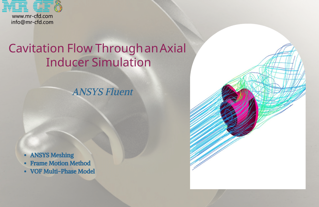
Cavitation Flow Through an Axial Inducer Simulation
$200.00 Student Discount
- The problem numerically simulates Cavitation Flow Through an Axial Inducer using ANSYS Fluent software.
- We design the 3-D model by the Design Modeler software.
- We Mesh the model by ANSYS Meshing software, and the element number equals 938174.
- We use the Frame Motion method to define the rotational movement in cell zone conditions.
- We use the VOF Multi-Phase model to define the two-phase flow, including liquid and vapor.
To Order Your Project or benefit from a CFD consultation, contact our experts via email ([email protected]), online support tab, or WhatsApp at +44 7443 197273.
There are some Free Products to check our service quality.
If you want the training video in another language instead of English, ask it via [email protected] after you buy the product.
Description
Cavitation Flow Through an Axial Inducer CFD Simulation, ANSYS Fluent Tutorial
This simulation is about cavitation flow through an axial inducer via ANSYS Fluent software. We perform this CFD project and investigate it by CFD analysis.
The cavitation phenomenon is one of the phenomena in that vapor bubbles are formed in the part of the fluid whose pressure is low. Sometimes there is a misconception that the only reason for this phenomenon and the formation of steam bubbles is because the liquid pressure reaches the vapor pressure (Pv).
However, various other factors and parameters cause this phenomenon to occur. For example, speed is one of the useful parameters in creating this phenomenon. The phenomenon of cavitation can cause many problems, including corrosion. Corrosion is very evident in the water pump.
We identify this phenomenon by the sound produced and the mechanical vibration produced. There are several ways to reduce this occurrence. One of the simplest methods is to increase the pump’s inlet pressure by reducing the distance between the pump and the tank.
Another way is to reduce the pressure drop and flow turbulence. Today, with the industry’s expansion, the need for pumps with smaller sizes and higher speeds is felt more. Therefore, it is necessary to improve the suction performance of pump impellers.
Inducers are essential components installed in front of the main impeller to achieve higher suction performance in the pump and rotate at the same impeller speed. The inducer can increase the inlet pressure to the pump impellers and improve the pump’s suction performance.
One of the most important phenomena that should be considered in pumps is the phenomenon of cavitation. One of the important reasons that inducers are used in pumps is to reduce cavitation.
The geometry of the present model is drawn by Design Modeler software. The model is then meshed by ANSYS Meshing software. The model mesh is unstructured, and 938174 cells have been created.
Cavitation Method
In this simulation, the Frame Motion method is used to define the rotational velocity of the inducer. In fact, the rotational speed equal to 15000 rpm is defined for the fluid around the inducer blades.
Also, to investigate the phenomenon of cavitation, a Multiphase Model should be used; Because the phenomenon of cavitation is caused by the phase change between liquid and vapor.
To define the multiphase model, the VOF model has been used. The characteristic of this model is that the separation boundary between the two phases is completely distinct. The liquid is defined as the primary phase and vapor is the secondary phase.
Cavitation Conclusion
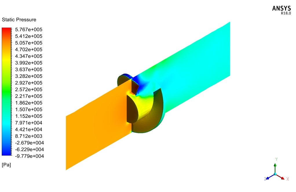
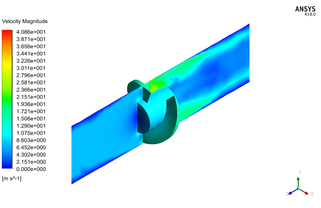
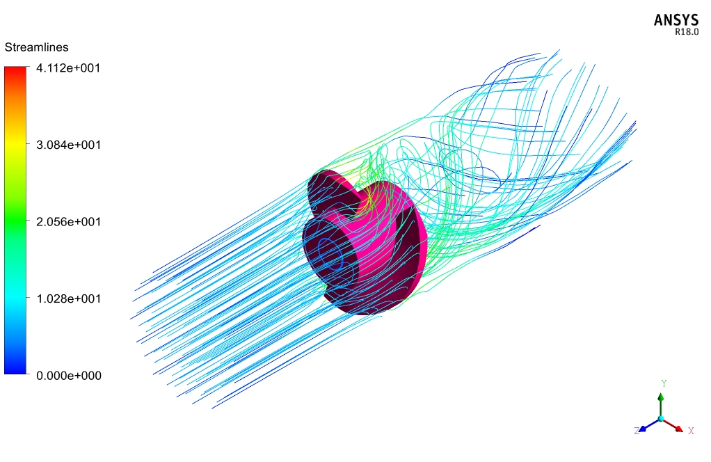
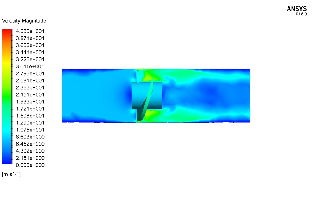
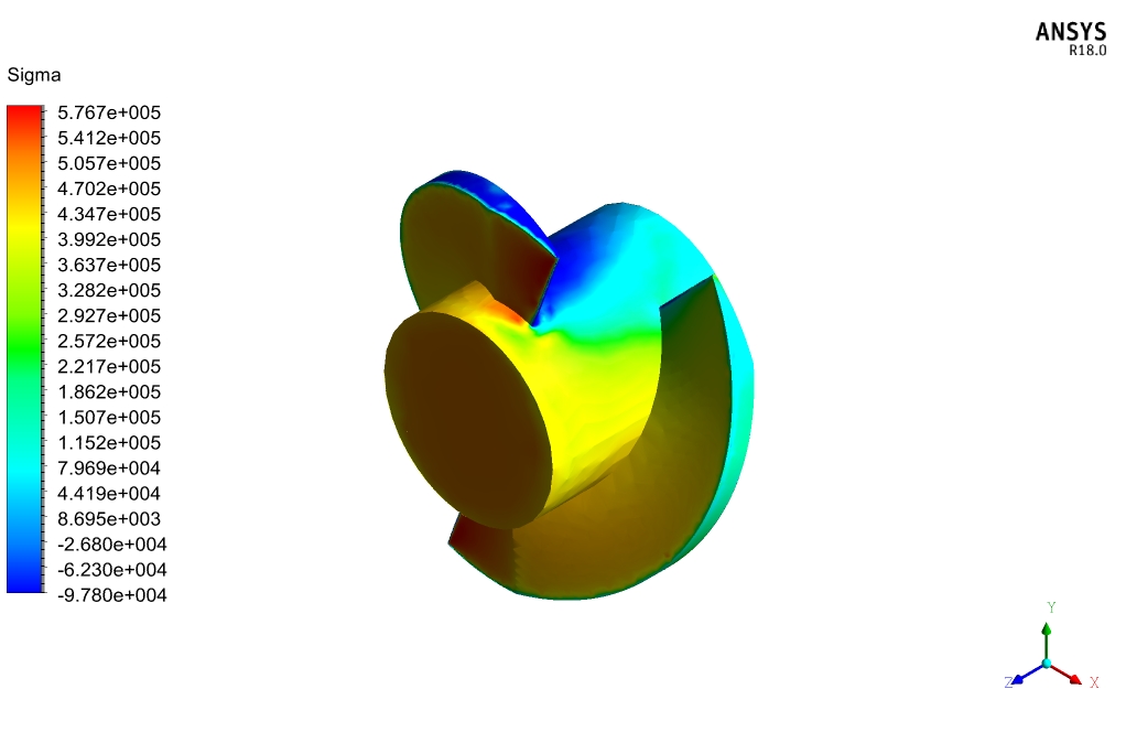
After simulation, the contours of velocity, pressure, and mass fraction of liquid and vapor are obtained. Also, streamlines around the inducer are obtained. The results show that as the fluid enters the inducers, the pressure increases.
If this inducer is connected to a pump, it is the output pressure and the maximum inducer pressure that the impellers have. The suction pressure at the back of the inducer has increased, which improves the pump’s suction performance.
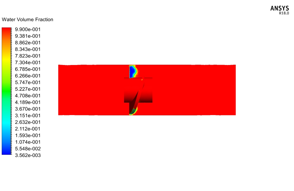
Velocity contours and Streamlines show that the velocity near the inducer has its maximum due to the angular velocity in this part. Also, the volume fraction contours show that cavitation has decreased.
Also, the velocity contours show that cavitation has decreased because the amount of water on the inducer is more than vapor.
Judd Senger –
Can the simulation model the effect of different fluid properties?
MR CFD Support –
Yes, the simulation can model the effect of different fluid properties, such as viscosity and density. We can adjust the fluid properties based on your specific requirements.
Dr. Rachel Funk IV –
The simulation of cavitation seems comprehensive, but I wonder if thermal effects are also taken into account in your model?
MR CFD Support –
In the given tutorial for the Cavitation Flow Through an Axial Inducer CFD Simulation, thermal effects are not explicitly mentioned. The focus is on the phase change from liquid to vapor due to pressure changes causing cavitation. If temperature and heat transfer are important for your use case, you may need to ensure a thermal analysis is incorporated in the CFD simulation.
Kariane Bergstrom –
I appreciate the clear breakdown of the simulation objectives and results! The explanation on how the use of inducers helps in reducing cavitation within pumps provides great insight.
MR CFD Support –
Thank you for your positive feedback! We’re glad to hear that you found the explanation informative and helpful. If you have any further questions or need more details, feel free to ask. Thank you for choosing our tutorial for your CFD learning needs.
Mariam Waelchi –
Can the simulation predict the temperature distribution in the inducer?
MR CFD Support –
Yes, the simulation can predict the temperature distribution in the inducer. This can be important for understanding the thermal effects in the inducer.
Prof. Corrine Gislason –
I’m curious if the simulation accounts for the temperature effect on the cavitation process, or is it only based on pressure changes throughout the fluid?
MR CFD Support –
In the described simulation, the cavitation process is modeled based on pressure changes and phase transition between liquid and vapor as they pertain to pressure changes. The VOF (Volume of Fluid) model is utilized for distinguishing between liquid and vapor phases. Temperature effects on cavitation are generally accounted for via the thermodynamic properties of the fluids involved. However, in the specific case described, the effect of temperature is not explicitly mentioned, suggesting the focus is on hydrodynamic aspects of cavitation rather than thermal effects.
Mr. Foster Auer I –
Were different rotation speeds considered in the cavitation study, and if so, how did these impact the cavitation phenomenon and pump performance?
MR CFD Support –
In the cavitation flow simulation through an axial inducer, we focused on a specific rotational speed of 15,000 rpm for the inducer. The effect of varying rotational speeds on cavitation and pump performance wasn’t the subject of this particular study. However, changes in rotation speed can significantly affect cavitation levels and pump efficiency due to alterations in local pressure fields and fluid velocities around the inducer blades.
Mr. Ryley Bruen –
I was wondering if the selection of the VOF model affects the accuracy of the cavitation simulation in any way?
MR CFD Support –
Absolutely! The choice of the Volume of Fluid (VOF) model directly impacts the accuracy of cavitation predictions. VOF is particularly efficient in capturing the distinct interface between the liquid and the vapor phases. Accurate interface tracking is crucial for a cavitation study since it allows for the clear identification of phase change locations, thus enabling the simulation to precisely predict the extent and effects of cavitation.
Gay Corwin III –
Can the simulation model the effect of different inducer materials?
MR CFD Support –
Yes, the simulation can model the effect of different inducer materials. We can adjust the material properties based on your specific requirements.
Mrs. Cleta Block –
I’ve noticed a detailed explanation of the cavitation phenomenon and its consequences on pump performance. Could you please elaborate on how the VOF method enables the distinct separation boundary between liquid and vapor during the simulation process?
MR CFD Support –
In the cavitation simulation using the VOF (Volume of Fluid) model, the model defines a clear interface between the liquid phase and the vapor phase. The VOF method tracks the volume fraction of each phase throughout the computational domain. This approach solves a single set of momentum equations and accounts for the presence of both phases by solving a phase fraction equation for the vapor phase while using the liquid phase as the primary one. In regions where vapor bubbles form, the volume fraction of the vapor phase increases. The distinct boundary between phases becomes apparent due to this sharp change in volume fraction values, capturing the cavitation phenomenon accurately.