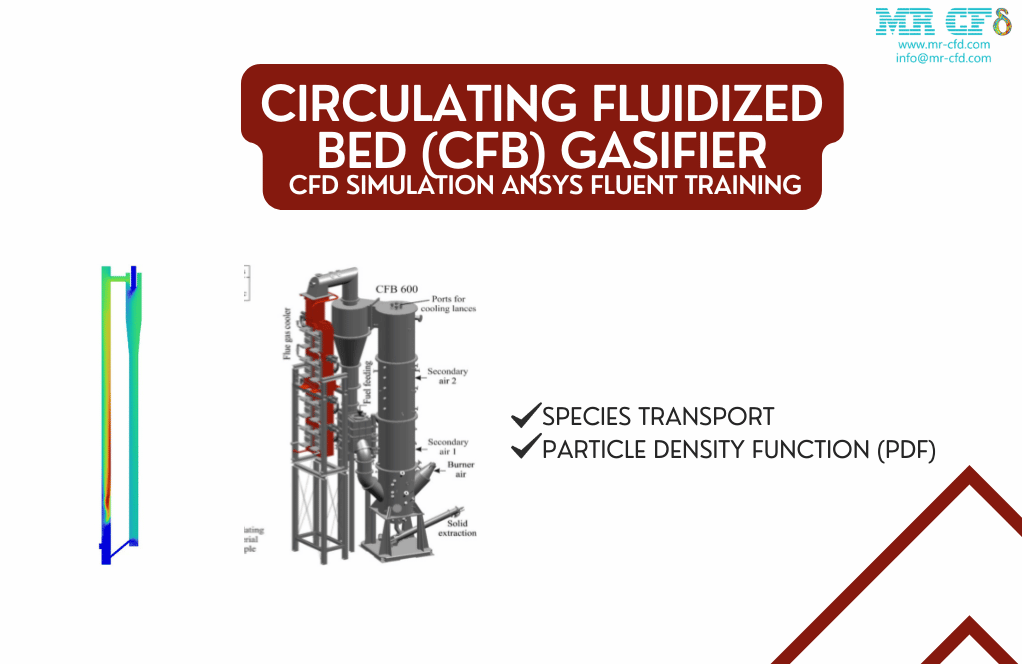
Circulating Fluidized Bed (CFB) Gasifier, CFD Simulation ANSYS Fluent Training
$260.00 Student Discount
In this simulation, a simple CFB cycle has been simulated, and results obtained.
Click on Add To Cart and obtain the Geometry file, Mesh file, and a Comprehensive ANSYS Fluent Training Video.To Order Your Project or benefit from a CFD consultation, contact our experts via email ([email protected]), online support tab, or WhatsApp at +44 7443 197273.
There are some Free Products to check our service quality.
If you want the training video in another language instead of English, ask it via [email protected] after you buy the product.
Description
Circulating Fluidized Bed Project Description
the Circulating Fluidized Bed gasifier is popular in industrial applications and academic studies because of its intrinsic advantages in high circulating rate, low operating temperature, broad fuel flexibility, and negligible pollutant emissions. In this simulation, a simple CFB cycle has been simulated, and results obtained.
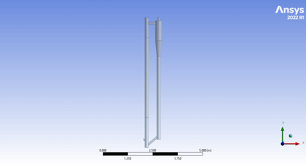
The system consists of two inlets, a vertical inlet for oxidizer and a horizontal inlet for fuel; the air and fuel, after mixed, start flameless combustion in a vertical section and then enter the cyclone to separate unburned ashes as polluted air, unburn fuel circulates to bottom of the downstream section and enters the process again and heavy sands and ashes exit from the bottom outlet. The particle density function (PDF) has been used in this simulation to simulate solid dynamics.
Geometry & Mesh
The 3-D domain of this simulation has been designed in ANSYS Design Modeler.
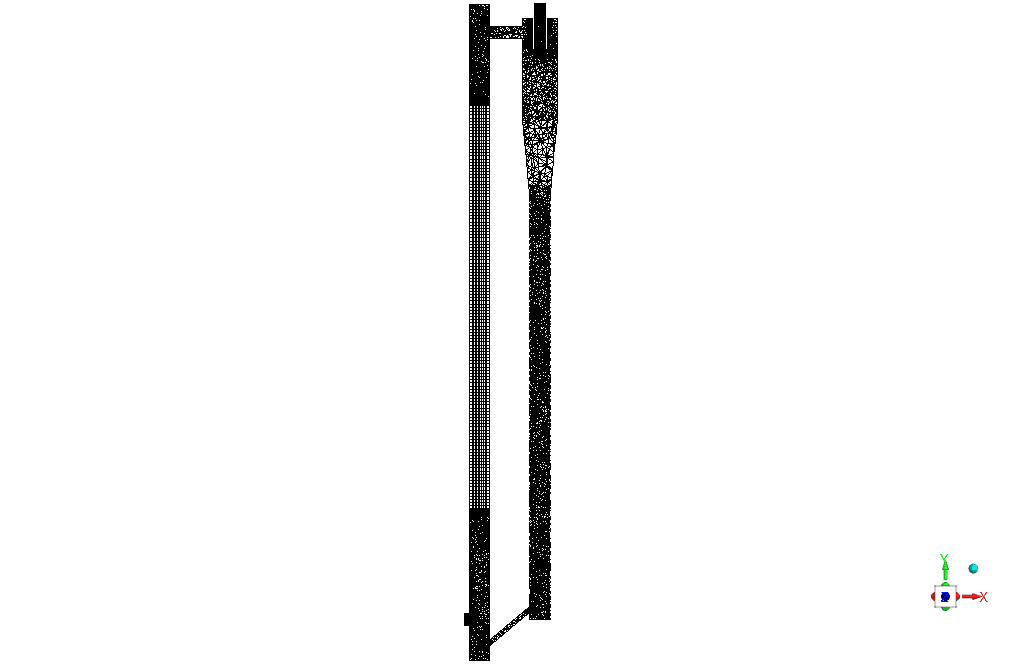
The meshing of this present model has been generated by ANSYS Meshing software. The mesh grid is unstructured, and the total cell number is 1537941 elements. The figure below shows an overview of the performed mesh.
CFD Simulation
To simulate the present model, several assumptions are considered, which are:
- The solver is pressure-based.
- The effect of gravity on the flow has been considered
- The hot zone wall model is considered a heat flux
The following is a summary of the steps for defining the problem and its solution.
| Models | ||
| k-epsilon | Viscous model | |
| Standard wall function | Near -Wall treatment | |
| Pressure based | Solver | |
| steady | Timestep | |
| Non – premixed combustion | Species model | |
| Chemical equilibrium | State relation | |
| Non-adiabatic | Energy treatment | |
| P1 | Radiation model | |
| On | Discrete phase model | |
| Unsteady particle tracking | Particle treatment | |
| Combusting | Injection type | |
| On | Energy | |
| Boundary conditions | ||
| Velocity-inlet | Air inlet | |
| 18 m/s | Fluid inlet velocity | |
| 300 k | Temperature | |
| 1 | Internal emissivity | |
| 0 | Soot mass fraction | |
| 0 | Mean mixture fraction | |
| 0 | Mixture fraction variance | |
| Escape | Discrete phase BC type | |
| Velocity inlet | Bio inlet | |
| 15 m/s | Particle inlet velocity | |
| 330 k | Temperature | |
| 1 | Internal emissivity | |
| 0 | Soot mass fraction | |
| 1 | Mean mixture fraction | |
| 0 | Mixture fraction variance | |
| Escape | Discrete phase BC type | |
| Pressure outlet | Cyclone outlet | |
| 0 | Supersonic gage pressure | |
| Pressure outlet | Qr outlet | |
| -120w | heat flux | |
| wall | Q2 wall | |
| stationary wall | wall motion | |
| heat flux | Thermal condition | |
| 250 w | heat flux | |
| wall | wall | |
| stationary wall | wall motion | |
| Non | Thermal condition | |
Circulating Fluidized Bed Results
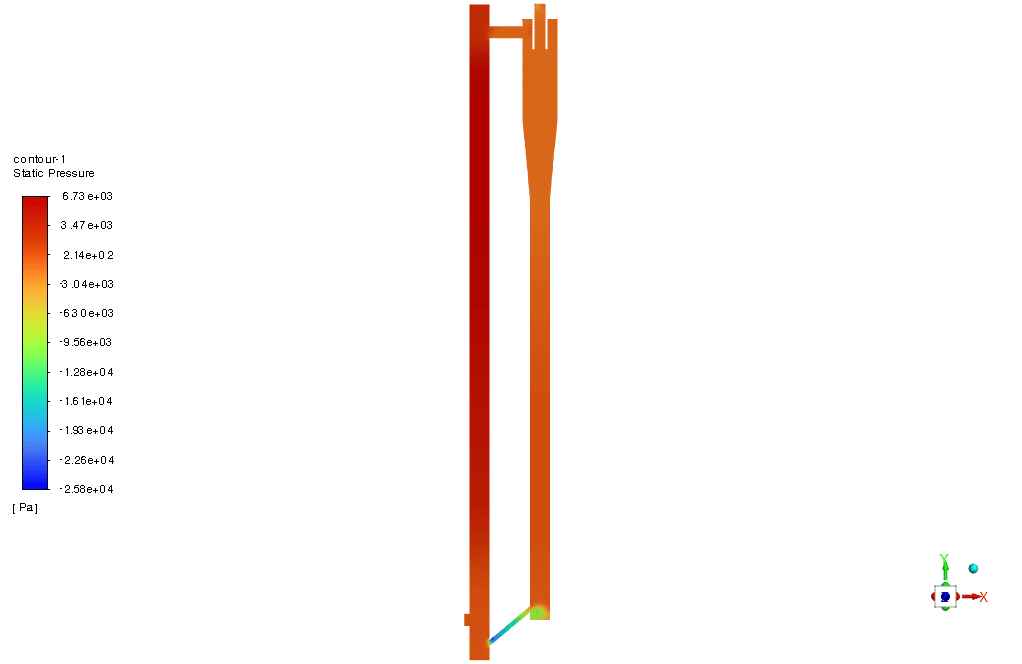
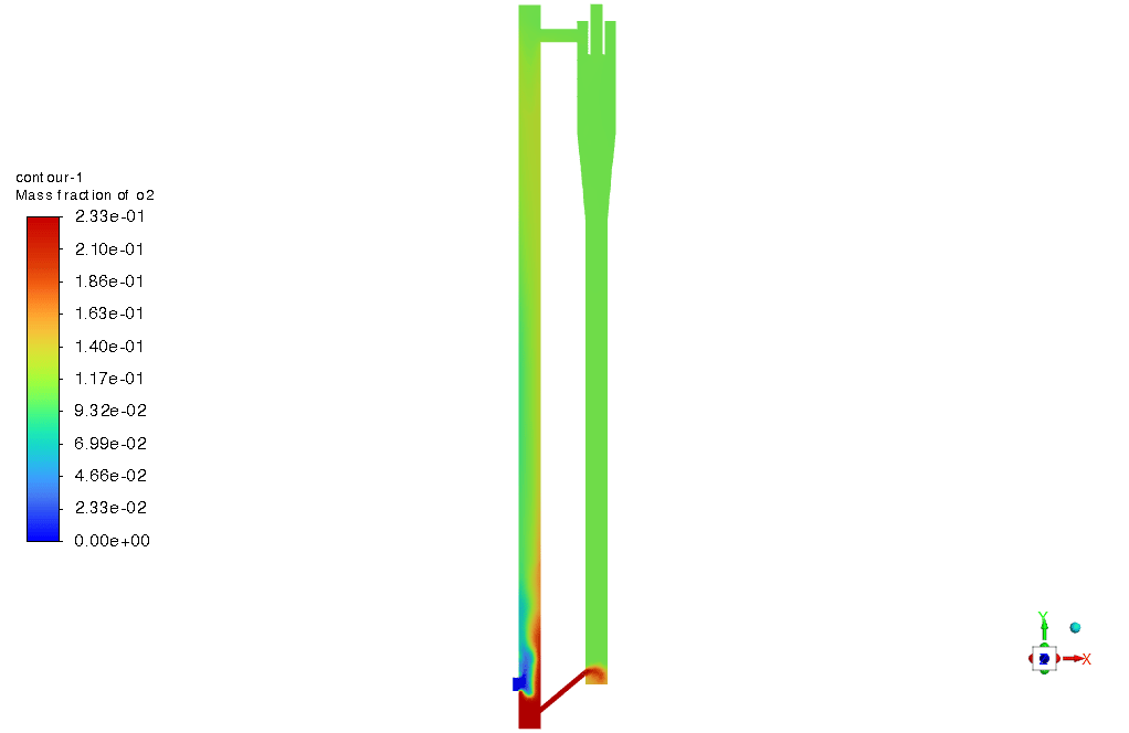
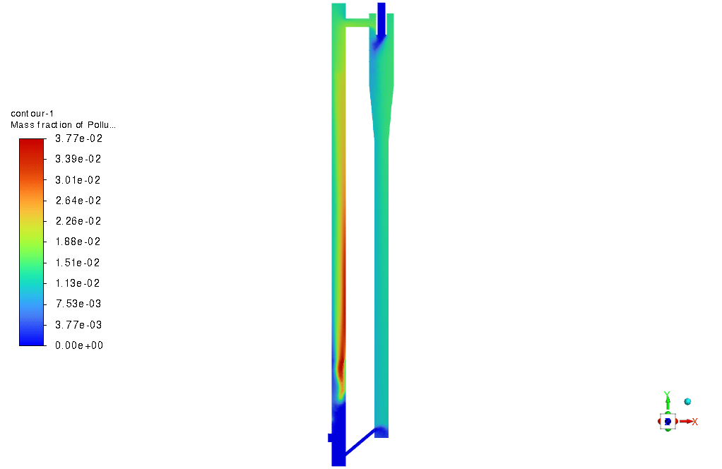
The simulation results show that the ignition of the fuel-air mixture in the vertical chamber and the hot gases resulting from the ignition is cooled in the cyclone and the second chamber, and the polluting gases of the maximum face are also examined. Unburned materials are separated inside the cyclone and re-entered the combustion process.
The counter below shows pressure, temperature, and gas volume fraction.

Miss Rebeka Macejkovic DVM –
I’m amazed by the detail in this simulation! Could you please elaborate more on how the Pressure Based Solver was used in the simulation of the CFB Gasifier?
MR CFD Support –
The pressure-based solver is suitable for incompressible and slightly compressible flows. It is instrumental in this simulation of the CFB Gasifier because the calculation involves the use of a continuity equation for mass conservation alongside the momentum equations. This combination provides the velocity field, pressure distribution, and other scalar values like temperature over the domain. Its application helps in ensuring accurate simulation of the combustion process and gas flow dynamics within the CFB Gasifier.
Dr. Timothy Pagac –
Fantastic detail on this CFB gasifier simulation! It was a comprehensive walkthrough. I assume non-premixed combustion with PDF has its advantages here, would you mind sharing a bit on why was this model chosen over others like a premixed model for this simulation?
MR CFD Support –
The non-premixed combustion model with a Probability Density Function (PDF) is chosen for such gasifier simulations due to its ability to accurately predict the mixing controlled chemical reactions that occur in a CFB environment. It allows for a more realistic simulation of the fuel and oxidizer entering the system separately and mixing during combustion, much like the physical environment inside a CFB gasifier. This model is particularly effective in systems with complex chemistry and flow dynamics, offering larger stability margins and accurate capturing of pollutants and temperature distribution in flameless combustion prevalent in such applications.
Jamar Hilpert –
I am thrilled with how detailed this CFB gasifier simulation is! The use of a PDF model to simulate solid dynamics seemed particularly innovative.
MR CFD Support –
Thank you for your kind words! We’re glad that you appreciate the intricacies of the CFB gasifier simulation and the implementation of the Particle Density Function (PDF) to effectively capture the dynamics of solids. It’s wonderful to hear that our customers recognize the innovation in our solutions.
Kristy Denesik –
Loved the breadth of this simulation! Still, I’m curious about how you defined the airflow and solid particles interaction. How did the circulating fluidized bed capture the dynamics of this complex multiphase interaction?
MR CFD Support –
In the CFD simulation of Circulating Fluidized Bed gasifiers, the interaction between the airflow and the solid particles is captured using a variety of computational models. The primary interaction is handled by the Discrete Phase Model (DPM), which can account for the particulate phase in a lagrangian framework, tracking the trajectory of individual particles as they interact with the continuous gas phase. The PDF transport model manages the distribution of particles and assists in simulating the combustion process within the bed. Combustion is simulated using the non-premixed combustion model, which factors in the chemical reactions between the fuel and the oxidizer. This intricate interplay creates a realistic depiction of a CFB gasifier’s operation.
Jordi Hickle –
I have a question about the combustion process. How does air and fuel combination lead to flameless combustion in this type of simulation, and what are the conditions to achieve that?
MR CFD Support –
In flameless combustion, a mixture of air and fuel produces combustion without a visible flame. In the CFB gasifier simulation, the conditions for flameless combustion include a high circulating rate of the oxidizer and fuel, a sufficient temperature in the combustion chamber to initiate reactions, and the proper fuel-air mixing to ensure that combustion occurs throughout the mixture rather than in a localized flame. The setup in this CFD simulation was designed to satisfy these conditions so that efficient and complete combustion can occur, reducing pollutant emissions and maximizing fuel usage.
Mrs. Theresa Hamill II –
Great detail in the CFB Gasifier simulation! Though I wonder, what were the key findings regarding emission levels and efficiencies? Were the results in line with the expected negligible pollutant emissions mentioned in the advantages?
MR CFD Support –
In relation to the simulation of the CFB Gasifier, the key findings indicated a successful simulation of flameless combustion and efficient separation of unburned materials and pollutants within the system. The predicted emission levels were notably low, reinforcing the advantage of CFB technology. The efficiencies observed were also consistent with expectations, illustrating the advantage of this system in industrial applications. Thank you for your inquiry and the opportunity to help clarify these outcomes.
Ms. Burdette Stoltenberg –
The review mentions a ‘non-premixed combustion’ model. Could you please explain the choice behind using non-premixed instead of premixed combustion model for this CFB gasifier simulation?
MR CFD Support –
In a CFB gasifier simulation like the one described, solid fuel particles and oxidizer tend not to mix before combustion. Therefore, a non-premixed combustion model is used to simulate the chemical reaction that occurs between the fuel and oxidizer at the microscopic level, where they come in contact within the combustion chamber. Premixed combustion models are typically used when the fuel and oxidizer are thoroughly mixed at a molecular level before they enter the combustion chamber, which might not be the case in a configuration of a CFB gasifier.
Toney Heathcote –
This is a very comprehensive review, but could you please tell me more about the results of the emission analysis from the CFB gasifier?
MR CFD Support –
The results of the emission analysis from the CFB gasifier are detailed in the simulation data, which indicate efficient combustion with low emissions. However, precise values for specific pollutants like NOx, CO, and particulate matter are available in the full report.
Tia Senger –
Can I see how pollutants are distributed throughout the gasifier? It’s crucial for my research on efficiency and emissions.
MR CFD Support –
Yes, in the results section, the distribution of pollutants would be shown using contours or volume fraction plots depicting temperature, pressure, and various species concentrations. It would provide actionable insights into the flow behaviors and pollutant distribution throughout the gasifier.
Gia Wilkinson V –
The detailed walkthrough was incredibly insightful! What software versions of Design Modeler and ANSYS Meshing were used for this project?
MR CFD Support –
I’m glad to hear the walkthrough was helpful to you! The specific versions of the ANSYS software tools used for the CFB gasifier simulation such as Design Modeler and ANSYS Meshing are typically stated in the documentation accompanying the CFD project or the training material. Generally, the most recent stable versions are used to ensure compatibility and access to the latest features during simulation.
Francisca Schultz –
The simulation results talk about the ignition in the vertical chamber. How exactly are inflammable conditions ensured in the CFB gasifier simulation?
MR CFD Support –
In the CFB gasifier simulation, inflammable conditions are established by specifying appropriate velocity inlet conditions for air and fuel, ensuring they mix properly. The combustion process is then initiated and maintained by setting the temperature high enough for ignition and utilizing non-premixed combustion and PDF to account for the solid dynamics of the gasification process. The presence of appropriate oxidizer inlet conditions and maintaining a controlled environment with heat fluxes on the walls fosters the ignition of the fuel-air mixture in the vertical chamber.