Two Stream Combustion, CFD Simulation ANSYS Fluent Training
$160.00 Student Discount
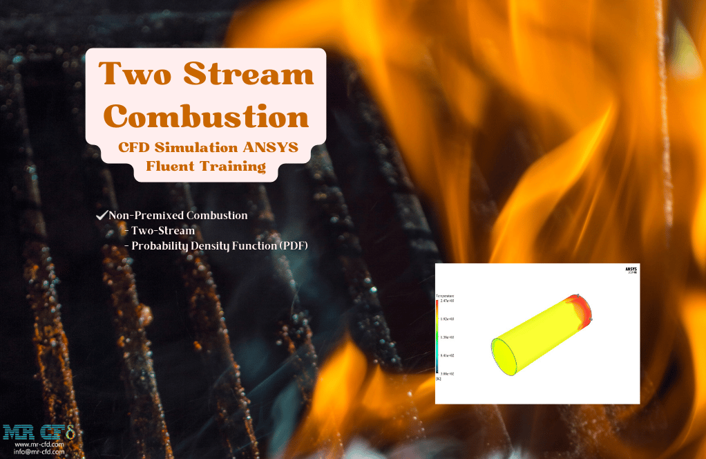
The present simulation is about two-stream combustion via ANSYS Fluent, and the results of this simulation have been analyzed.
Click on Add To Cart and obtain the Geometry file, Mesh file, and a Comprehensive ANSYS Fluent Training Video.To Order Your Project or benefit from a CFD consultation, contact our experts via email ([email protected]), online support tab, or WhatsApp at +44 7443 197273.
There are some Free Products to check our service quality.
If you want the training video in another language instead of English, ask it via [email protected] after you buy the product.
Description
Two Stream Combustion Description
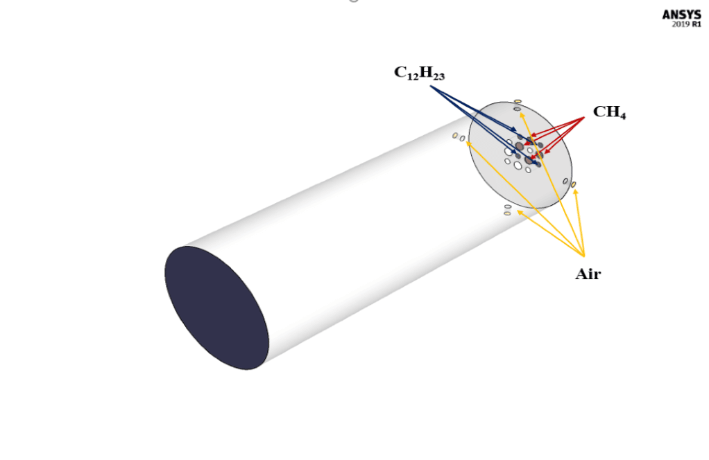
The present simulation is about two-stream combustion via ANSYS Fluent. The combustion reaction occurs when air is combined with hydrocarbon fuel to convert fuel energy into heat energy. Sometimes two fuel streams are used to carry out the combustion reaction. The reaction by which two fuel streams react with an oxidizer is called two-stream combustion. In this project, a horizontal cylindrical combustion chamber is modeled. Methane (CH4) and diesel (C12H23) are used as fuel to combine with the oxidant to produce a combustion reaction. In this combustion chamber, four separate inlets are installed for each primary fuel, secondary fuel, and oxidizing stream. CH4 stream with a flow rate of 0.02 kg/s and a temperature of 810 K, C12H23 stream with a flow rate of 0.02 kg/s and a temperature of 723 K, and oxidizer with a flow rate of 1.2 kg/s and a temperature of 530 K enters the combustion chamber. The species model has been used to define the combustion reaction in this numerical simulation. The species model is also defined in a non-premixed combustion mode. In this type of combustion, fuel and oxidizer enter the reaction zone of the combustion chamber through separate paths; That is, they do not mix before entering the combustion chamber. In the non-premixed combustion model, the definition of a mixture fraction is used, which represents the mass fraction derived from the fuel stream. Also, since secondary fuel is used in this combustion chamber, the secondary stream must be activated.
Geometry & Mesh
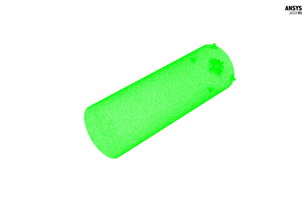
The present geometry is designed in a 3D model via Design Modeler. The computational zone is the interior of a horizontal cylindrical combustion chamber. In the inlet section of this combustion chamber, four inlets for primary fuel, secondary fuel, and airflow are designed.
The mesh of the present model has been done via ANSYS Meshing. Mesh is done unstructured, and the number of production cells equals 505082.
Set-up & Solution
Assumptions used in this simulation :
- Pressure-based solver is used.
- The present simulation is steady.
- The effect of gravity on the model is ignored.
| Models | ||
| Viscous | k-epsilon | |
| k-epsilon model | realizable | |
| near-wall treatment | standard wall function | |
| Species | Non-Premixed | |
| energy treatment | non-adiabatic | |
| stream option | secondary stream | |
| fuel temperature | 810 K | |
| oxide temperature | 723 K | |
| second temperature | 530 K | |
| species | fuel : 1CH4
oxide : 0.79N2 & 0.21 O2 second : 1C12H23 |
|
| Energy | On | |
| Boundary conditions | ||
| Inlet-Fuel | Mass Flow Inlet | |
| mass flow rate | 0.02 kg.s-1 | |
| temperature | 810 K | |
| mean mixture fraction | 1 | |
| Inlet-Oxid | Mass Flow Inlet | |
| mass flow rate | 1.2 kg.s-1 | |
| temperature | 358.15 K | |
| mean mixture fraction | 0 | |
| Inlet-Secondary | Mass Flow Inlet | |
| mass flow rate | 0.02 kg.s-1 | |
| temperature | 530 K | |
| secondary mean mixture fraction | 1 | |
| Outlet | Pressure Outlet | |
| gauge pressure | 0 Pascal | |
| Wall | Wall | |
| wall motion | stationary wall | |
| heat flux | 0 W.m-2 | |
| Methods | ||
| Pressure-Velocity Coupling | SIMPLE | |
| pressure | standard | |
| momentum | first-order upwind | |
| turbulent kinetic energy | first-order upwind | |
| turbulent dissipation rate | first-order upwind | |
| mean mixture fraction | first-order upwind | |
| mean mixture variance | first-order upwind | |
| secondary mean mixture fraction | first-order upwind | |
| secondary mean mixture variance | first-order upwind | |
| energy | first-order upwind | |
| Initialization | ||
| Initialization methods | Hybrid | |
Two Stream Combustion Results
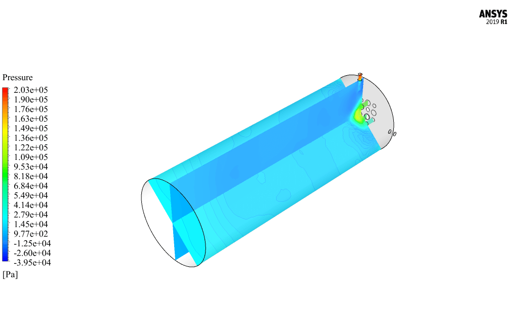
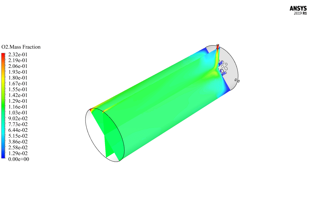
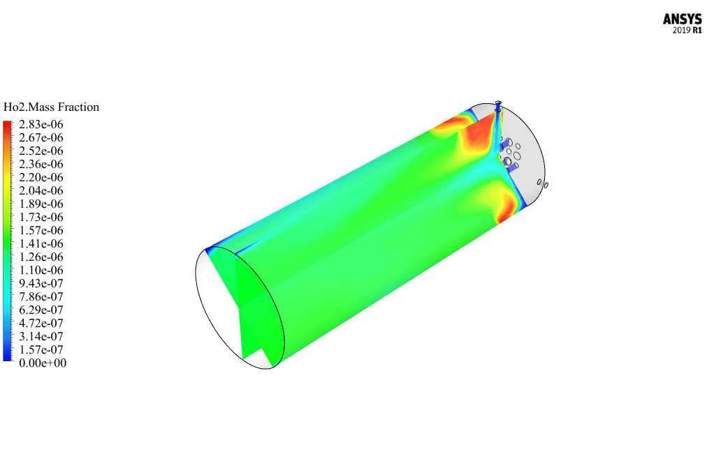
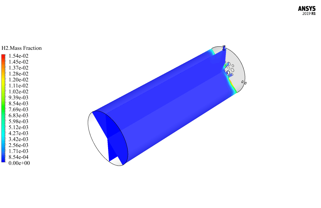
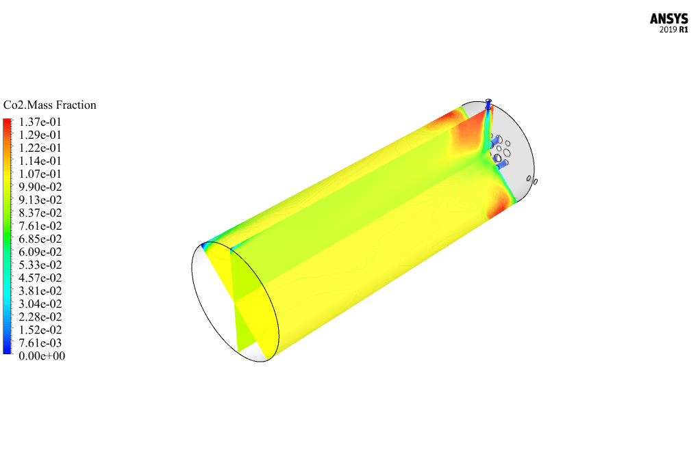
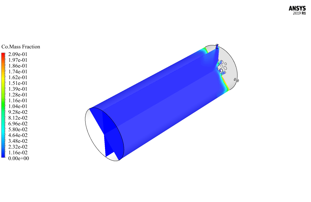
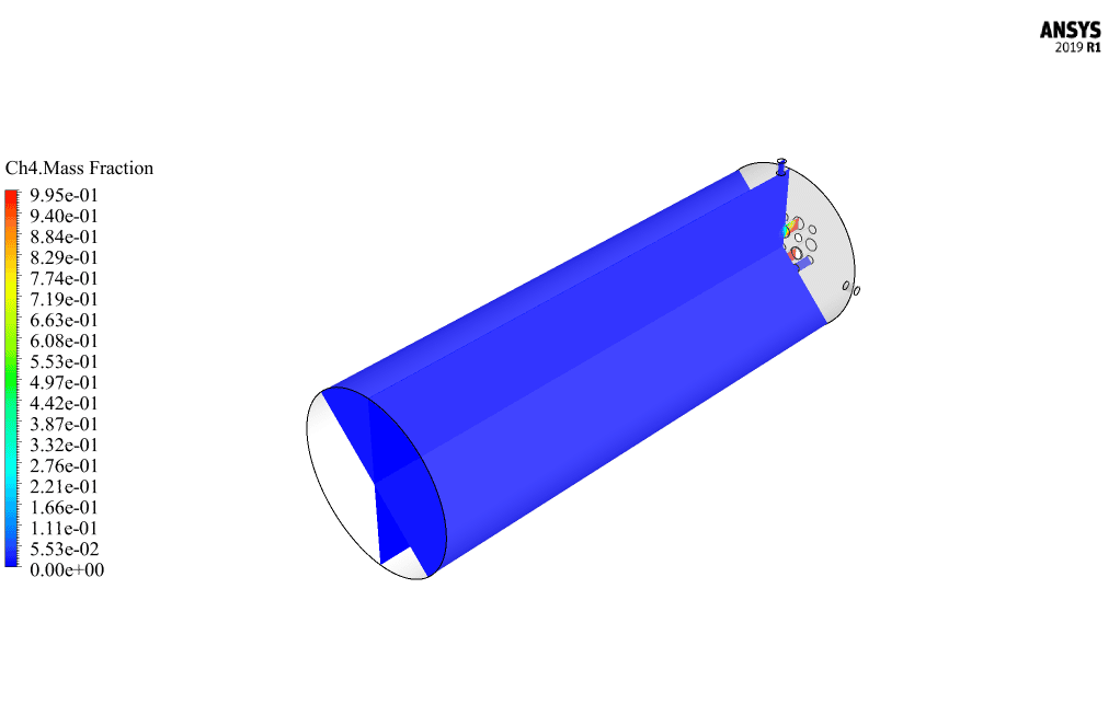
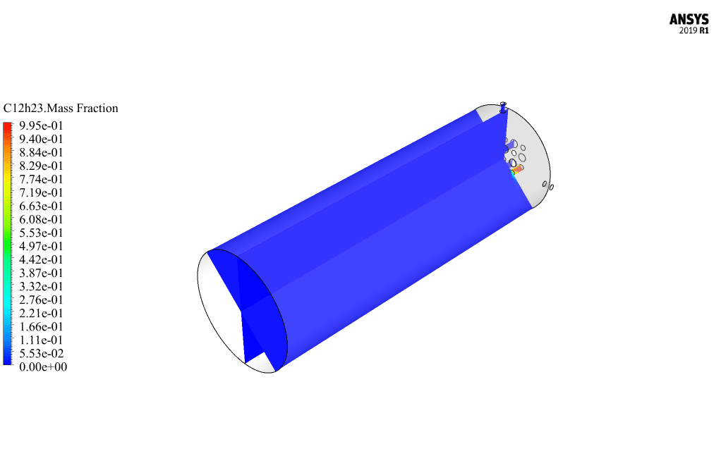
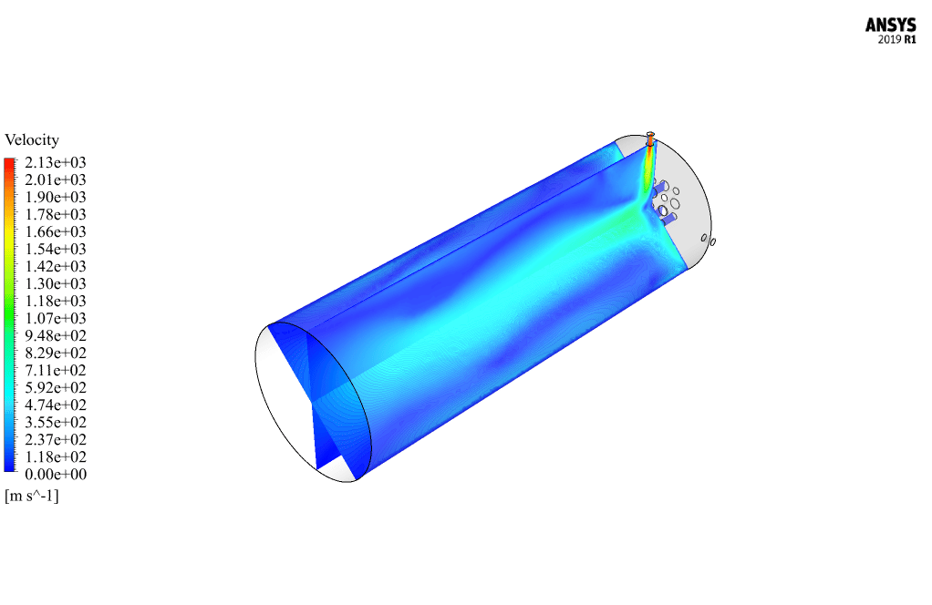
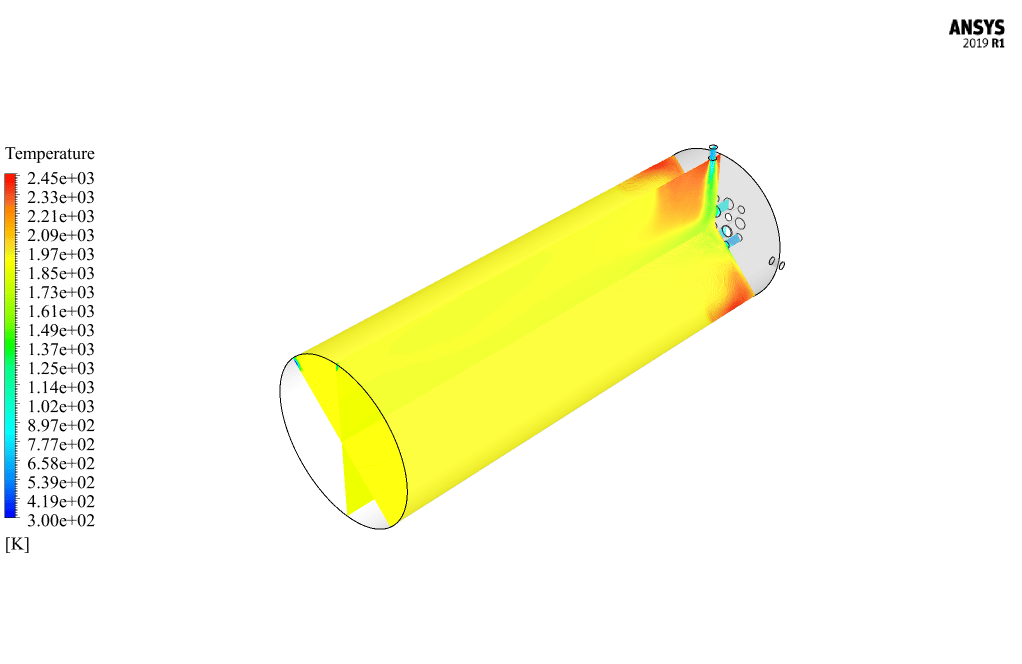
After calculation, 2D and 3D contours related to pressure, velocity, temperature, and species’ mass fraction ( CH4, CO2, C12H23, O2, H2O, H2, CO ), water-liquid volume fraction, and water-vapor volume fraction are obtained. The results show that the temperature in the reaction zone increases significantly. In other words, where the primary and secondary fuel streams and the oxidizing stream inside the combustion chamber combine, the combustion reaction occurs. As a result, high thermal energy is produced. Also, at the beginning of the combustion chamber, the mass fraction of each reactant (including CH4, C12H23, and O2) decreases, and then the amount of each of the reaction products (such as CO2, CO, H2O, etc. ) increases. This indicates that the combustion reaction is taking place correctly and that as a result of this reaction, fuel and oxidizing streams are converted into reaction products.
Ms. Tatyana Macejkovic Sr. –
I recently finished the Two Stream Combustion training, and the presentation of results was particularly impressive. How do the 2D and 3D contour plots help in better understanding the combustion process in this simulation?
MR CFD Support –
The 2D and 3D contour plots provide a visual representation of the various parameters within the combustion chamber. By visualizing data like pressure, velocity, temperature, and species’ mass fractions, we can better understand how the reactants mix and react over spatial dimensions. The contours highlight regions of high temperature and illustrate the progression and efficiency of the combustion process, allowing us to analyze the areas where the primary and secondary fuel streams combine with the oxidant most effectively.
Miss Elinor Fritsch –
Just finished the Two Stream Combustion CFD Simulation course and wow – I really have to commend the illustrative results! Seeing the 2D and 3D contours for each aspect like pressure, temperature, and various species mass fractions was super insightful. It truly deepened my understanding of how fuel and oxidizing streams interact in combustion reactions. Fantastic resource!
MR CFD Support –
We’re thrilled to hear that you found the Two Stream Combustion CFD Simulation course both insightful and educational! We aim to provide high-quality, illustrative content to help our clients grasp complex concepts effectively. Thank you for your positive feedback, and we hope you continue to find value in our learning products!
Prof. Mellie Lemke Jr. –
The training demonstrated exceptional clarity and the simulation was top-notch! The movement from reactants to products was especially fascinating to learn about.
MR CFD Support –
Thank you so much for your positive feedback! We’re thrilled that our training on two-stream combustion simulation could provide you with clear insight into the combustion process and the transition from reactants to products. Your appreciation is greatly valued!
Alena Torphy –
Really impressed with the in-depth explanation of two-stream combustion and the clear setup outlined in the simulation. The thorough details of the boundary conditions and setup show the dedication in replicating a realistic combustion process. Keep up the excellent work!
MR CFD Support –
We truly appreciate your positive feedback. It’s great to hear that our detailed explanation met your expectations and helped better understand the two-stream combustion simulation using ANSYS Fluent. We strive to provide clear, accurate, and comprehensive information in our training materials. Thank you for taking the time to acknowledge our efforts!
Estel Heidenreich –
I found the content about the non-premixed combustion model to be particularly insightful. I appreciate how the mixture fractions and combustion dynamics are detailed.
MR CFD Support –
Thank you for your kind words. We’re thrilled to hear that the content was helpful to your understanding of non-premixed combustion models and their intricacies. Stay tuned for more educational content!
Mariane Lubowitz –
I’m so pleased with the Two Stream Combustion CFD course by MR CFD! The depth of insight into non-premixed combustion modelling is beyond valuable. Understanding species transportation and reaction zone depiction in the chamber clarified the subject for me.
MR CFD Support –
Thank you for taking the time to write such a positive review! We are delighted to hear that our Two Stream Combustion CFD course met your expectations and provided you with a clear understanding of non-premixed combustion modeling. Your feedback is greatly appreciated, and we hope our learning products continue to contribute to your success in the field!
Maximo Kohler –
This ANSYS Fluent training on two-stream combustion was incredibly informative. The detailed setup instructions and clear explanation of the results clarified the complexity of simulating combustion processes. It was particularly insightful to see how different mixture fractions and inlet conditions influenced the reaction outcomes.
MR CFD Support –
We’re delighted to hear that the training was helpful and educational for you. Understanding the nuances of combustion simulations can indeed be challenging, but we’re glad that our training materials made it more accessible. Thank you for sharing your positive experience with us!
Drew Macejkovic Jr. –
This is by far one of the best CFD simulation courses I’ve taken! The way the two-stream combustion was taught and simulated in ANSYS Fluent helped me not just understand, but actually perform these complex simulations with confidence. The results were astonishing and very close to theoretical predictions. Kudos to the team for putting together such an effective training program!
MR CFD Support –
We’re thrilled to hear that our Two Stream Combustion, CFD Simulation in ANSYS Fluent training has been so helpful to you. Your ability to perform complex simulations with confidence is exactly what we aim for with our course participants. Thank you for your kind words, and we’re here to support you with any further learning you tackle!
Prof. Lempi Turner –
Great training course, diligently given details through the simulation setup and problem-solving. Exactly what I was looking for to understand the non-premixed combustion model!
MR CFD Support –
Thank you for taking the time to leave us a positive review. We are thrilled that you found the details of the non-premixed combustion model helpful and that the training course met your expectations. If there’s anything else you would like to learn, just let us know!