
Pin and Plate Heat Sink Performance Comparison
$120.00 Internship
The present simulation is about Pin and Plate Heatsink Heat Transfer by ANSYS Fluent, and the results of this simulation have been analyzed.
Click on Add To Cart and obtain the Geometry file, Mesh file, and a Comprehensive ANSYS Fluent Training Video.To Order Your Project or benefit from a CFD consultation, contact our experts via email (info@mr-cfd.com), online support tab, or WhatsApp at +44 7443 197273.
There are some Free Products to check our service quality.
If you want the training video in another language instead of English, ask it via info@mr-cfd.com after you buy the product.
Description
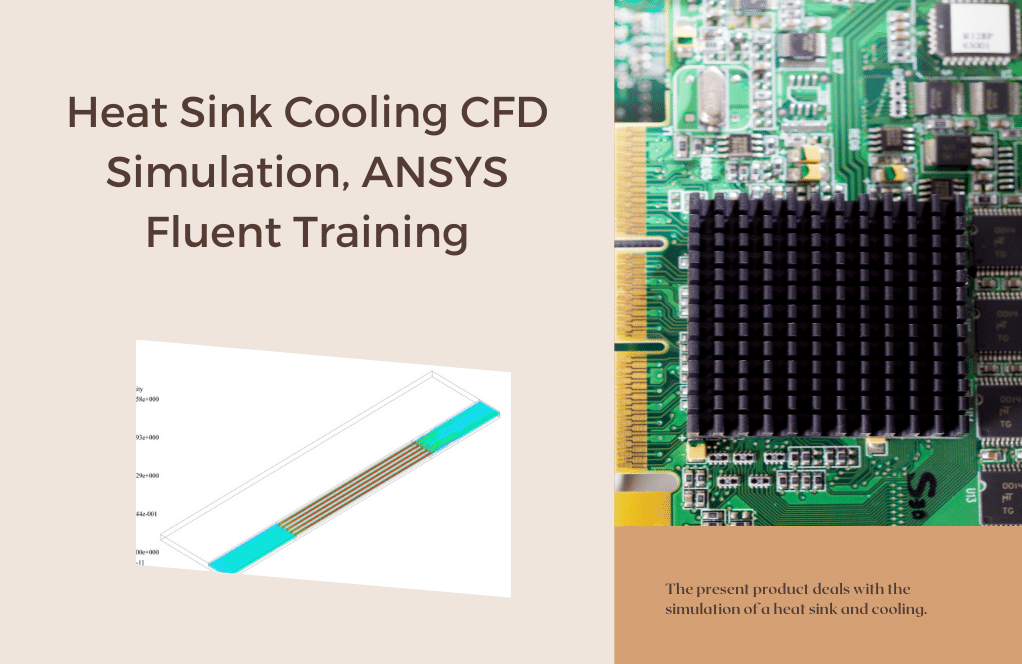
Pin and Plate Heat Sink Performance Comparison, ANSYS Fluent CFD Simulation Training
A Heatsink is a passive heat exchanger that transfers the heat generated by an electronic or a mechanical device to a fluid medium, often air or a liquid coolant, where it is dissipated away from the device, thereby allowing regulation of the device’s temperature. A heat sink is designed to maximize its surface area in contact with the cooling medium surrounding it, such as the air. Air velocity, choice of material, protrusion design, and surface treatment affect the performance of a heat sink. Heat sink attachment methods and thermal interface materials also affect the die temperature of the integrated circuit. Thermal adhesive or thermal paste improves the heat sink’s performance by filling air gaps between the heat sink and the heat spreader on the device. A heatsink is usually made out of aluminum or copper.
The system consists of four different heatsinks; heatsinks are in two general shapes one is a pin fin, and the other is a plate-fin; each shape has to case to study; one is the normal heatsink. The second one is with holes designed on their surface, and the goal of this study is to determine the absorbing effect of these holes and the total heatsink shape on their heat transfer rate.
Geometry & Mesh
The 3-D domain of this simulation has been designed in ANSYS Design Modeler. The meshing of this present model has been generated by ANSYS Meshing software. The mesh grid is unstructured. The figure below shows an overview of the performed mesh.


CFD Simulation
To simulate the present model, several assumptions are considered, which are:
- The solver is pressure-based.
- The effect of gravity on the flow has been considered
- The hot zone wall model is considered a constant temperature
The following is a summary of the steps for defining the problem and its solution
| Models | ||
| k-omega | Viscous model | |
| SST | ||
| Pressure based | Solver | |
| steady | Time step | |
| Energy | on | |
| Boundary conditions | ||
| Velocity-inlet | Air inlet | |
| 0.1 m/s | Fluid inlet velocity | |
| 300 k | Temperature | |
| Pressure outlet | outlet | |
| 0 | Supersonic gage pressure | |
| wall | Sink wall | |
| stationary wall | wall motion | |
| heat flux | Thermal condition | |
| 2500 w | heat flux | |
| wall | hot wall | |
| stationary wall | wall motion | |
| 330 k | Temperature | |
Pin and Plate Heat Sink Heat Transfer Results
The results of the simulation show static temperature contours. The simulation results show that the hole-less sinks had a better performance level. This life is because it increases the useful surface due to the low thickness of the plates and pins. A hole-less plate heatsink has the highest heat transfer value of 10.986 watts, 10.5682 watts of heat transfer compared to a hole in its wall.
On the other hand, compared to plate and pin heatsinks, plate heatsinks have shown better heat transfer due to having a higher level. The pinhole heatsink transmits 8.61 watts of heat at the same 30 ° C temperature difference, outperforming the 8.52-hole perforated pin sink.
Reviews
You must be logged in to post a review.

William Russel Jr. –
I used the hole-less plate heatsink model for my project and it dissipated heat very efficiently!
MR CFD Support –
Thank you for your feedback! We’re glad to hear that the hole-less plate heatsink model from our ANSYS Fluent training worked well for your project. If you have more questions or need further assistance, feel free to reach out.
Celestine Armstrong DVM –
I am thoroughly impressed with the detailed analysis of the different heatsink designs. It’s fascinating to see how the presence of holes impacts the heat transfer efficiency. Will similar simulations also test for different airflow rates and their impact on heat sink performance?
MR CFD Support –
Thank you for your appreciation of our simulation work and for your question. In this study, we exclusively focused on heat dissipation performance by comparing heatsinks with and without holes at a set airflow rate. We’ve not currently provided simulations with varied airflow rates. Including varied airflow rates in a comprehensive simulation study could provide further insights into the heat transfer performance under different cooling conditions, which can be beneficial for practical applications.
Ladarius Buckridge –
Just wanted to share my appreciation for this complex CFD simulation study using ANSYS. The insights into pin and plate-fin heat sinks performance are extremely valuable for optimizing thermal management systems. Kudos to MR CFD for presenting such detailed work which is both informative and practically applicable. The meticulous approach towards investigating the effect of structural design differences like the addition of holes on heat transfer efficiency underlines the importance of simulation in design. Excellent training material for both academic purposes and industrial applications!
MR CFD Support –
Thank you for your kind words and thoughtful review! We are pleased to hear that you found the pin and plate heatsink comparison study informative and practically valuable. At MR CFD, we are committed to providing comprehensive simulations and training to help designers and engineers optimize their thermal management systems. Your feedback is greatly appreciated and motivates us to keep producing high-quality CFD simulations. Thank you again for choosing our learning product.
Dejah Wyman –
I was wondering if a different air inlet velocity was considered, and if so, how that impacted the effectiveness of the heatsink performance.
MR CFD Support –
In the simulation project described, only a flow velocity of 0.1 m/s is mentioned as the air inlet velocity. If various inlet velocities were analyzed and their impacts on heatsink performance measured, that information was not detailed in this review. Changes to the airflow velocity can significantly affect the heat transfer rate due to the resulting changes in Reynolds number and flow dynamics around the heatsink fins.
Ms. Jacynthe Lubowitz –
Fascinating study comparing pin and plate heat sinks. Do the results suggest that the plate heat sink without holes is the most efficient for all applications, or is there a specific scenario where a different design might work better?
MR CFD Support –
Thank you for your interest in the study. Indeed, while the results indicate that the plate heat sink without holes exhibits the highest heat transfer value for the configurations tested, the efficiency can vary based on application-specific requirements. Certain factors—including size constraints, airflow patterns, cooling medium, and power densities—might make alternative designs more suitable for specific scenarios or devices.
Mr. Kaleigh Bergnaum V –
I was fascinated by the detailed analysis of the heatsink performance. Great work on identifying the cooling efficiency between hole-less and hole-designed heat sinks!
MR CFD Support –
Thank you for your kind words and for recognizing the efforts in our CFD analysis between various heatsink designs. We’re pleased to hear you appreciated the detailed study and the results we’ve presented!
Mr. Chaim Deckow IV –
What are the key factors that affect the performance of a heat sink as per the provided description?
MR CFD Support –
The performance of a heat sink is affected by various factors including the air velocity, material selection, design of the protrusions (pin or plate fins), surface treatment, and heat sink attachment methods. Additionally, the presence or absence of holes on the heat sink surface, the use of thermal adhesive or thermal paste, and the heatsink’s surface area in contact with the cooling medium are also key factors affecting its heat transfer rate and overall performance.
Miss Euna Rowe I –
The training for the Pin and Plate Heat Sink Performance Comparison really broke down complex CFD concepts into understandable portions. Every step of the process, from geometry and mesh to final results, was clearly explained. It definitely helped me assist my team more effectively in optimizing heatsink designs. I appreciate the attention to detail, especially in providing side-by-side comparisons for different heatsink configurations.
MR CFD Support –
Thank you for your positive feedback! We’re thrilled to hear that our Pin and Plate Heat Sink Performance Comparison training helped you and your team. Our goal is to provide comprehensive learning materials that make complex subjects accessible and practical. If you need any further assistance or have any questions in future projects, don’t hesitate to reach out. We’re always here to support you in advancing your CFD skills.
Kelsi Tillman DDS –
My heatsinks are installed in a small enclosed space. Will placing holes still affect the heat transfer rate?
MR CFD Support –
While our simulation results have shown that, generally, hole-less heatsinks have a higher heat transfer value due to increased useful surface area, the impact of placing holes in a heatsink within a small, enclosed space might differ significantly. Thermal dynamics within such an environment can vary and depend on other factors such as airflow pattern, the proximity of components, the presence and efficiency of other cooling components, ambient temperatures, etc. It may be beneficial to run a specific simulation for your scenario to get the most accurate information.
Prof. Leonel Effertz DVM –
I’m very impressed with the Pin and Plate Heat Sink Performance Comparison in ANSYS Fluent. The detailed analysis and comparison between plate-fin and pin-fin heatsink designs, with and without holes, provided insightful data on heat transfer efficiency. The exploration of different materials, air velocities, and the effect of surface treatment on heatsink performance was especially enlightening. It’s clear that this training not only taught the fundamentals of CFD analysis but also delved into practical design considerations for optimizing heat dissipation. Great work!
MR CFD Support –
Thank you for your kind words! We are thrilled to hear that you found the Pin and Plate Heat Sink Performance Comparison in ANSYS Fluent insightful and that it provided you with a detailed understanding of heat transfer efficiency in different heatsink designs. At MR CFD, we aim to deliver comprehensive learning experiences that cover both theory and real-world application. Your feedback is greatly appreciated, and it motivates us to continue creating high-quality learning products. If you require any further information or assistance in future studies, please do not hesitate to reach out.
Prof. Richard Schultz –
I just finished one of the simulation trainings about Pin and Plate Heat Sink Performance, and I’m amazed by the in-depth analysis provided. The comparison between hole-less and hole-included heat sinks was thoroughly explained and insightful. The detailed discussion on how variations in design influence heat transfer rates provided a clear understanding of the importance of surface area maximization. It’s quite fascinating to see that in this case, the hole-less plate heatsink turned out to be more efficient.
MR CFD Support –
Thank you for your positive feedback! We’re thrilled that our simulation training on Pin and Plate Heat Sink Performance aided in deepening your understanding of heat transfer principles in heat sink designs. Your recognition of the level of detail and analysis we provide is highly appreciated. If you have any more insights or queries regarding our simulations, please feel free to share them!
Mr. Hoyt Franecki II –
The results from the pin and plate heat sink performance comparison were enlightening. It’s interesting to note the efficiency gains in hole-less designs due to increased surface area. Quality content and great insights into heat sink design optimization!
MR CFD Support –
Thank you for your positive feedback! We’re glad to know that you found the insights valuable and that the comparison between the pin and plate heat sinks was informative for you. If you have any further questions or need assistance with your heat transfer projects, feel free to reach out.
Dr. Seamus Buckridge –
I’m really impressed by the details dealing with heat sinks provided in the Pin and Plate Heat Sink Performance Comparison tutorial. It was enlightening to learn about the factors that affect heat sink performance. The results presented are convincing, particularly the comparison between hole-less and holey sinks in terms of heat transfer efficiency. Great work on explaining the intricacies of heat transfer in such an easily understandable manner.
MR CFD Support –
Thank you for your kind words and positive feedback! We’re delighted to hear that you found the tutorial on Pin and Plate Heat Sink Performance Comparison both informative and easy to understand. Our aim is always to provide clear and detailed explanations to help our customers better understand the nuances of heat transfer and assist them in their learning journey. Should you have any more queries or need further assistance with your CFD learning experience, please don’t hesitate to reach out!
Madge Feest –
I’m fascinated by the impact of the holes on the heatsinks’ heat transfer rates and how this study can help in optimizing electronics cooling. Great work!
MR CFD Support –
Thank you so much for your positive feedback! We’re thrilled to hear that you found the study on the impact of holes in heatsinks and their heat transfer rates insightful. If you have any more questions or need further information, feel free to reach out. Your interest and satisfaction with our CFD simulation training resources are highly appreciated!
Mrs. Madelyn Bechtelar MD –
The attention to detail in modelling heat sink performance was fantastic. The clear differentiation between pin and plate designs, along with and without holes, provided comprehensive insight into how each design influences heat dissipation. Great use of ANSYS Fluent tools!
MR CFD Support –
Thank you for taking the time to provide feedback on our Pin and Plate Heat Sink Performance Comparison simulation training. We’re thrilled to hear you appreciated the thorough approach and found the insights valuable. Continued learning success!
Darrell Wehner –
I am absolutely impressed by the heat transfer performance comparison between different heatsink designs using ANSYS Fluent. It’s fascinating to see how the presence or absence of holes impacts the efficiency and what role the shape of the heatsink plays. This kind of analysis is invaluable for optimizing thermal management solutions. Great job with the detailed simulation and results presentation!
MR CFD Support –
We appreciate your positive feedback on the Pin and Plate Heat Sink performance comparison! It’s fantastic to hear that the analysis has provided you with valuable insights into optimizing your thermal management strategies. Thank you for acknowledging the detail and effort put into the simulation and the presentation of results. Should you have any more queries or require further assistance, feel free to ask. We are here to help!
Pearline Rowe DDS –
The training for the pin and plate heat sink was very insightful. I now understand how the variation in design impacts thermal regulation. Was there a data calculation section that I missed, perhaps responding to various real-world scenarios?
MR CFD Support –
I am glad you found the training insightful. The primary focus of the course was on comparing the performance of different heat sink designs using ANSYS Fluent simulations. If you are referring to additional calculations or case studies mimicking real-world applications, these topics might not be explicitly covered in the preset training material. Nonetheless, the principles and methodologies can certainly be applied to various real-world situations beyond the scope of the training.
Josiah Bruen –
This was such an insightful comparison on pin fin and plate-fin heatsinks! I’m particularly impressed by the detailed analysis of heat sinks with holes designed on their surfaces, and the surprising finding that hole-less sinks showed better performance.
MR CFD Support –
Thank you for your positive feedback! We’re delighted to hear that our simulation training offered you valuable insights, and we’re glad that the detailed comparison was useful to you. If you have any further questions or need more information, feel free to reach out to us!
Ms. Yvonne Runolfsson I –
I’m fascinated by the comparison between the pin and plate heatsinks with holes and those without. The insights from the simulation were impressive, and seeing how the geometry modifications impact heat transfer efficiency is enlightening.
MR CFD Support –
Thank you for your positive feedback on our Pin and Plate Heat Sink Performance Comparison CFD simulation training! We are thrilled to hear that you found the results enlightening and that you were able to appreciate the value of geometry modifications in heat transfer efficiency. It’s always rewarding to know that our simulations are helping others gain clearer insights into thermal management. Thank you once again for your kind words and for using our training materials.
Prof. Isac Shanahan –
I found the study on the heat sink performance fascinating! The physical properties and geometries involved in heat dissipation have always intrigued me. Out of curiosity, did you examine any alterations in airflow characteristics around the heat sinks due to the presence of holes?
MR CFD Support –
Our simulation indeed looked into changes in airflow characteristics. The presence of holes in heatsinks alters the airflow path, creating different turbulence patterns which might affect the heat transfer rates because they provide an additional pathway for convection. These nuances are part of what we aim to understand with our comparative simulations.
Sydni Stracke Jr. –
As a CFD novice, I was fascinated by the comparative study between pin and plate heat sinks. The detailed insights on heat transfer performance aided greatly in understanding the underlying principles. Will this training module assist in optimizing heat sink designs for specific applications?
MR CFD Support –
Absolutely, this training module on pin and plate heat sink performance comparison using ANSYS Fluent provides fundamental insights that can be applied to optimizing heat sink designs. It illustrates the influence of geometry and structural changes on the heat transfer rate. Through understanding the CFD analysis and simulation results, designers can make informed decisions to enhance the heat dissipation efficiency tailored to specific applications.
Dr. Shea Volkman –
I decided to try the heatsink CFD simulation to better understand how different designs affect performance. The one with holes designed in their surfaces sounds interesting. It seems slightly counterintuitive, but I guess there’s a detailed explanation for this phenomenon?
MR CFD Support –
In the CFD simulation, you correctly observed that heatsinks with holes performed differently. While it might seem that holes could disrupt effective heat transfer by reducing the material available for conducting heat, they might also contribute to enhanced convection through increased airflow or change the flow dynamics in a beneficial way depending on the specific heatsink geometry and cooling conditions. The results generally depend on the balance between material conduction and airflow convection, which is explicitly covered in the training material.
Selena Russel –
I am impressed with the comprehensive analysis between the different heatsink designs provided in the training. Is there any visual comparison of the temperature distribution between the four heatsink models?
MR CFD Support –
Thank you for your review! Yes, in the training, we indeed provide visual comparison materials such as static temperature contours for all four heatsink models. This allows you to visually assess the temperature distribution and understand the heat transfer efficiency for each design.
Melody Lemke –
I was able to follow the tutorial for setting up the pin and plate heat sink comparison in ANSYS Fluent, and the results were amazing! Seeing the heat transfer properties visually really helped grasp the importance of design changes. Keep up the great work in delivering such insightful content!
MR CFD Support –
Thank you for your positive feedback! We’re delighted to hear that our tutorial was helpful to you and that you were satisfied with the results. Understanding design influence on heat transfer is crucial, and we’re glad we could assist in enhancing your knowledge. If you need more resources or have any questions in the future, please feel free to reach out!
Mellie Hintz –
The results show that hole-less heat sinks perform better, but does the presence of holes ever benefit heat transfer under different conditions or with different materials?
MR CFD Support –
The study highlights that under the set conditions, hole-less heat sinks performed better due to increased useful surface area. Presence of holes might benefit heat transfer if they are designed to increase turbulence or airflow, leading to enhanced convection. Material properties also play a crucial role, so holes in a heat sink made of material with higher thermal conductivity could potentially improve performance in different scenarios.
Mrs. Irma Bernhard –
The training states that the hole-less sinks performed better. Can you explain how the presence of holes affects heat dissipation?
MR CFD Support –
In this simulation, heat dissipation is impacted by the surface area that is exposed to the cooling medium. While holes add complexity and may disrupt airflow patterns, increasing turbulence, the simulation showed that hole-less sinks had better heat transfer. This suggests that, in this case, the increased surface area of the unperforated fins and plates allowed for more effective heat dissipation, therefore appearing more efficient compared to their counterparts with holes.
Prof. Brittany Wyman DDS –
I’m impressed by the detailed comparison of pin and plate heat sinks. The influence of drilled holes on heat transfer is fascinating!
MR CFD Support –
We’re glad you found the comparison insightful and appreciate the positive feedback. Ensuring our customers understand the nuances of heat transfer in different heat sink designs is a priority for us.
Jevon Rath MD –
I was impressed with the level of detail in the results, especially with regards to the heat transfer values of the various heat sink designs. The comparison between hole-less and perforated sinks was particularly enlightful.
MR CFD Support –
Thank you for your positive feedback on our simulation training for the ‘Pin and Plate Heat Sink Performance Comparison’ using ANSYS Fluent. We are glad that you found the results insightful and that the detailed heat transfer analysis met your expectations. We strive to deliver comprehensive learning experiences, and it’s always encouraging to hear that our work is appreciated.
Dr. Troy Yost –
I’m trying to understand the influence of the holes on the heat sinks in your simulation. Could you clarify—does having holes increase or decrease the heat sinks’ performance?
MR CFD Support –
In our simulation study, we analyzed the heat transfer rate of different heat sink designs, including models with and without holes. The results indicated that the heatsinks without holes exhibited superior performance. This is likely due to the increased effective surface area that facilitates heat dissipation in the solid versions. Specifically, the hole-less plate heatsink achieved the highest heat transfer rate compared to its counterpart with holes. Hence, in our simulation, heatsinks without holes demonstrated better efficiency in transferring heat.
Shawna Rohan –
This training material provided a clear comparison of pin and plate heat sinks. The detailed simulation approach was particularly useful, illustrating the impact of design differences on performance.
MR CFD Support –
Thank you for sharing your feedback! We’re thrilled to hear our training material was helpful to you. If you have any more questions or need further assistance, feel free to reach out.
Roslyn Runte –
I am thrilled with the thorough comparative study between pin and plate heat sinks done by MR CFD Company. The detailed investigation into the effects of shapes and hole induction on the performance was insightful. Not only did I appreciate the collection of comprehensive data on heat transfer rates, but I also found the analysis of heat sink efficiency according to various modifications extremely helpful for my research. It’s exciting to see how modifications can impact overall thermal management!
MR CFD Support –
Thank you for your positive feedback! We’re glad to hear that our study on pin and plate heat sinks was helpful to your research. Our team is dedicated to providing detailed and insightful analysis to help our customers understand the intricacies of CFD and its applications. If you have any further research needs or questions, please don’t hesitate to reach out to us. Your success is our success!
Mrs. Lia Borer III –
The simulation data for the Pin and Plate Heat Sink performance comparison is clear and well-presented, highlighting the effects of design variations effectively.
MR CFD Support –
We appreciate your taking the time to review our training materials on the Pin and Plate Heat Sink Performance Comparison using ANSYS Fluent. It’s wonderful to hear that you found the presentation of the data clear and comprehensive. Your feedback is highly valued!
Brenden Feeney –
I recently completed the Pin and Plate Heat Sink Performance Comparison ANSYS Fluent simulation course and I have to say I’m thoroughly impressed. The level of detail and the comparison between different heatsink designs were eye-opening. This course has deepened my understanding of how design tweaks can affect thermal management in practical applications. Well done on such an informative course!
MR CFD Support –
Thank you for your wonderful feedback! We’re thrilled to hear that the course was able to enhance your understanding of heat sink design and thermal management. Your insights on the importance of design details in influencing heat transfer are spot on. If you have any more questions or need further assistance, please don’t hesitate to reach out. We appreciate you choosing our course for your learning journey!
Mrs. Chasity Bernier II –
I struggled to understand the impact of various designs on the heat transfer performance. Could you clarify how the presence of holes influences heat dissipation in pin versus plate heat sinks?
MR CFD Support –
In this simulation, it was observed that the heat sinks without holes had a better performance in heat dissipation. This is because they have a greater effective surface area for heat transfer. In a heat sink, more surface area generally means more space for heat to be transferred to the surrounding air. By adding holes, the surface area might decrease, leading to less heat being transferred away from the hot wall. The pin fin heat sink with holes dissipated 8.52 watts, while the same pin fin without holes dissipated 8.61 watts; this slight difference signifies that in this case, a solid structure without additional holes was more beneficial for heat transfer compared to having holes.
Jaeden Parker III –
I noticed the study found that the hole-less sinks performed better in terms of heat transfer. Could you explain why this might be the case?
MR CFD Support –
The hole-less sinks offer a higher effective surface area for heat transfer, as there are no interruptions that can reduce the amount of surface available for conducting heat. The continuous material structure allows for more consistent distribution of heat, leading to more efficient heat dissipation from the sink to the surrounding cooling medium. This is why the hole-less designs tend to perform better compared to designs with holes.
Mallory Wolf –
The simulation results on pin and plate heat sinks are insightful! The comparative analysis has showcased the performance differences effectively. Good job on drawing conclusions based on heat transfer values, and I appreciate the clear explanation of why the hole-less sinks outperformed the other designs.
MR CFD Support –
Thank you for your positive feedback! We’re delighted to hear that you found the comparative analysis of the pin and plate heat sinks useful and the conclusions clear. Our goal is to provide detailed and informative simulation results that can help users understand the performance characteristics of different heat sink designs. If you have any more questions or need further assistance, feel free to reach out to us!
Mr. Elton Quigley V –
This product led to impressive results in comparing heat sink performance. The detailed CFD simulations assessed different shapes and configurations effectively. The insights into heat dissipation strategies are crucial for optimizing electronics cooling. Kudos to the team for presenting an understandable and practical guide to heat sink design. It’s definitely a source of valuable knowledge for thermal management applications.
MR CFD Support –
Thank you for your kind words! We’re thrilled to hear that you found our Pin and Plate Heat Sink Performance Comparison so insightful and practical. It’s always our goal to provide valuable and understandable content that enhances learning and application in real-world scenarios. If you have any further feedback or need assistance with another CFD simulation, feel free to reach out!
Ofelia Dooley –
The results really highlight the effectiveness of these heat sinks. Incredible job on demonstrating the contrasting performances between pin and plate heatsinks and the effects of holes!
MR CFD Support –
Thank you for your kind words! We’re thrilled to hear that you found the comparison insightful. Our team strives to provide clear and detailed analyses to help understand such complex phenomena.
Cierra Romaguera –
I was impressed with your CFD training on comparing the heat sink performance. The results clearly communicated which heat sink designs were more efficient. Can you tell me if surface treatments were also considered in this performance comparison, or were only the holes and shapes investigated? If not, is it suggested to use some surface treatments to further enhance heat sink efficiency?
MR CFD Support –
In this training, the primary focus was to compare the heat transfer rates of different physical designs – particularly the presence of holes and the shape of the heat sinks. Surface treatments were not included in this comparison. However, using surface treatments can indeed enhance heatsink efficiency by improving thermal contact or increasing emissivity. These methods are supplementary to the core design and can be explored in additional simulation scenarios for comprehensive optimization.
Jevon Wiegand Jr. –
I must say, the detailed information on different heat sink performances was eye-opening! I never knew how much of a difference holes in heat sinks could make in heat transfer efficiency. The comparison between the different designs has provided valuable insights that could be massively useful for my hardware projects. Great job on conducting such an in-depth analysis!
MR CFD Support –
Thank you for your positive feedback! We’re thrilled to hear that you found the performance comparison of the pin and plate heat sinks so insightful. It’s fantastic to know that our simulation training aided in your understanding of heat transfer efficiency in these systems. We strive to provide comprehensive analysis to assist our customers with their projects. If you need further assistance or information, feel free to reach out!
Anya Hickle PhD –
The results highlight the hole-less sinks as better performers. Are there any specific scenarios where heatsinks with holes might be more advantageous?
MR CFD Support –
Heatsinks with holes might be more advantageous in scenarios where weight reduction is crucial, improved airflow is required, or in situations that benefit from directed fluid flow. They can also be beneficial in applications where acoustic dampening is desired, as perforations may disrupt sound waves.
Alessandra Labadie –
I’m curious about the material of the heatsinks used in this simulation. Could you specify whether aluminum or copper was utilized and how the choice of material impacted the simulation results?
MR CFD Support –
In this simulation, we explore the performance of both aluminum and copper heatsinks due to their different thermal conductivity. We analyze how heat transfer rates are affected by these materials in both pin and plate-fin designs, providing insights into the efficiency of each material within the various heatsink configurations.