Cylindrical Heat Source CFD Simulation by ANSYS Fluent Tutorial
Free
- The problem numerically simulates a Cylindrical Heat Source using ANSYS Fluent software.
- We design the 3-D model by the Design Modeler software.
- We Mesh the model by ANSYS Meshing software, and the element number equals 1600000.
- We define an Energy Source to define the heat from the aluminum cylinder body.
To Order Your Project or benefit from a CFD consultation, contact our experts via email ([email protected]), online support tab, or WhatsApp at +44 7443 197273.
There are some Free Products to check our service quality.
If you want the training video in another language instead of English, ask it via [email protected] after you buy the product.
Description
Description
This simulation is about a cylindrical heat source via ANSYS Fluent software. We perform this CFD project and investigate it by CFD analysis.
In this project, the steady heating process of airflow in a cylindrical geometry is investigated. Airflows in the hollow space between two concentric cylinders while a constant heat source of 252972 W/m3 heats the air.
A solid aluminum cylinder is used as a heat source. Air enters and exits the domain with a temperature equal to 300 K and 1758 K, respectively.
The geometry of the present model is drawn by Design Modeler software. The model is then meshed by ANSYS Meshing software. The model mesh is unstructured, and 1600000 cells have been created.
Cylindrical Heat Source Method
In this simulation, a Heat Source is defined in the cell zone condition to define the heat from the aluminum cylinder body. This heat source indicates that a certain heat value is produced volumetrically per unit of time and is continuously distributed in the computing zone.
Cylindrical Heat Source Conclusion
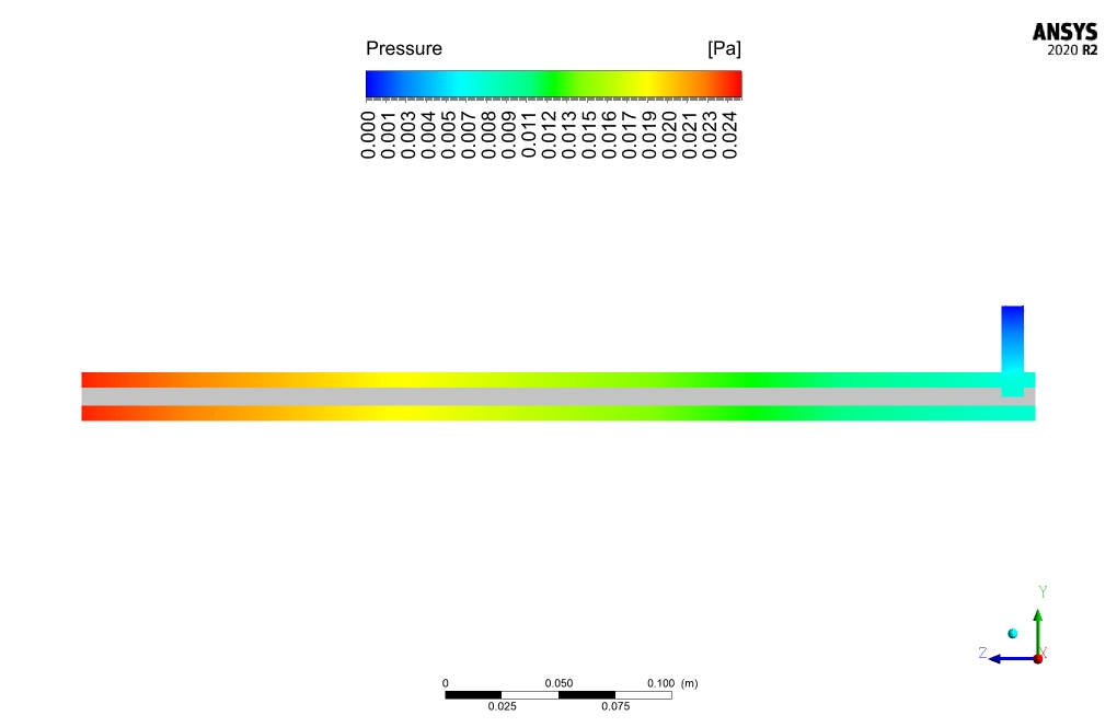
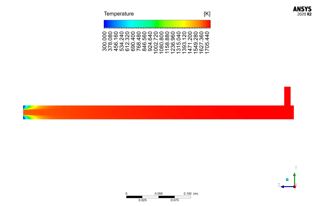
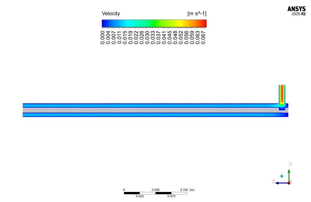
After simulation, the contours of temperature, velocity, and pressure are obtained. Airflow average velocity at the inlet and outlet is 0.00878484 m/s and 0.0353417 m/s, respectively.
This significant rise in velocity magnitude is due to the reduction of the cross-sectional zone of flow. Air temperature at the inlet and outlet is equal to 300 K and 1759 K, respectively, resulting in a heat transfer rate of 3.4 W/m2.
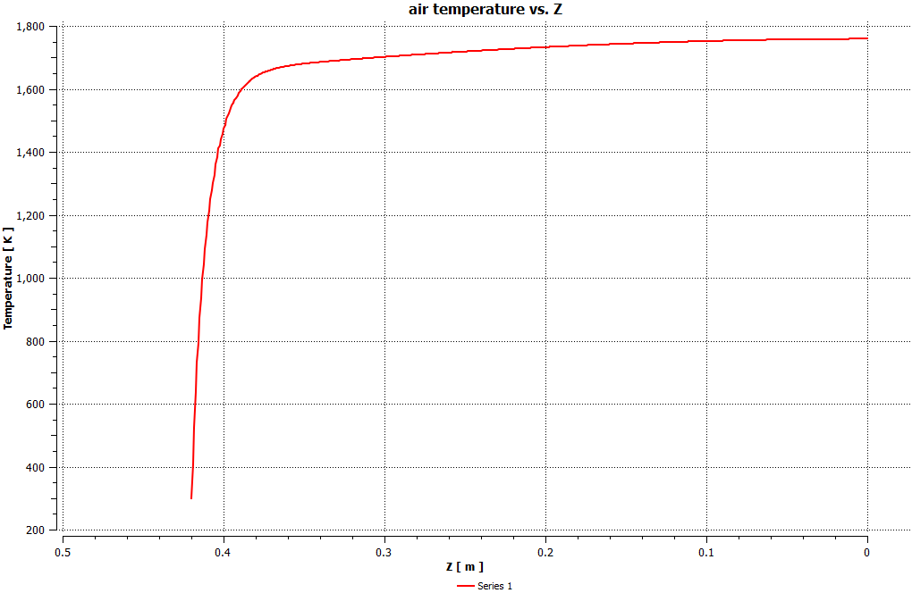
Also, the plot of the fluid temperature along the axial direction of the model has been obtained. The plot shows that the temperature of the fluid is increasing during the model. Also, the maximum temperature increase occurs in the model’s initial areas.


Julien Satterfield MD –
I’m impressed with the simulation results! The gradient of the temperature increase and velocity changes are very informative.
MR CFD Support –
Thank you for your positive feedback! We’re glad to hear that the simulation results have proven insightful for you. If you have any further questions or curiosities about the process or the results, don’t hesitate to reach out.
Emma Luettgen –
Fantastic learning resource! The step-by-step guidance on setting up the heat source and analyzing the effect on airflow was very clear. The comprehensive view provided for temperature and velocity changes enhanced my understanding of the heat transfer phenomena in cylindrical geometries.
MR CFD Support –
Thank you for your kind words! We are thrilled to hear that our tutorial on the cylindrical heat source CFD simulation was helpful for you. Understanding the complexities of heat transfer is very important, and we’re glad that our resources made a difference in your learning experience. If you need further assistance or have more questions, please do not hesitate to reach out!
Lenna Howe –
I’m intrigued by the simulation setup for the cylindrical heat source. Can you please explain a bit more about how the temperature of the air vastly increases as it moves through the model?
MR CFD Support –
As air moves through the space between the two concentric cylinders, it is subjected to the constant volumetric heat source from the solid aluminum cylinder. The heat source heats the air, gradually increasing its temperature. Additionally, due to heat transfer principles, when air passes through the heated section, it gains thermal energy which significantly enhances its thermal state, hence a stark temperature increase is observed. The continuity of heat source and the conductive properties of aluminum further promote this temperature rise along the axial direction.
Haven Wolf V –
Just finished going through the ‘Cylindrical Heat Source CFD Simulation by ANSYS Fluent Tutorial’ and it’s excellent. The explanation of the heat transfer phenomenon and the temperature contour analysis were especially helpful. As someone fairly new to CFD analysis, your step-by-step approach really clarified the concepts for me. Incredible job!
MR CFD Support –
Thank you for your kind words and we are thrilled to hear that you found our tutorial so accessible and informative. It’s our goal to present complex concepts in a way that’s easy to understand for learners at all levels. Your enthusiasm for the content encourages us to keep creating high-quality learning materials. Keep exploring and happy simulating!
Kira Crist –
I’m impressed by the results shown in this tutorial. It’s clear that there’s an incredible amount of heat transfer taking place, quite accurately simulating the real-life scenario. Good job on showcasing the temperature gradient along the axial direction.
MR CFD Support –
Thank you for your kind words! We’re delighted to hear that our tutorial was helpful and met your expectations. If you ever have more questions or need further assistance, feel free to reach out. We’re always here to help!
Martine Ebert –
The insight on temperature variation within the model was fantastic. Really helped me understand the heat transfer process in practical scenarios!
MR CFD Support –
Thank you for your positive feedback! We’re glad our simulation was able to provide clear understanding on temperature variation and heat transfer. If you need any more information or further simulations, please let us know!
Rosa Heathcote –
I just finished the ‘Cylindrical Heat Source CFD Simulation by ANSYS Fluent Tutorial’ and I’m really pleased with how comprehensive the tutorial was! The step-by-step instructions made it easy to follow along and the results were very clear.
MR CFD Support –
Thank you for your positive feedback! We’re thrilled to hear that you found the ‘Cylindrical Heat Source CFD Simulation by ANSYS Fluent Tutorial’ comprehensive and straightforward. It’s great to know that the tutorial was clear and helpful in guiding you through the simulation process. We appreciate you taking the time to let us know about your experience!
Prof. Carlie Carter –
I recently completed a study on cylindrical heat sources using your ANSYS Fluent tutorial, and I have to say, it’s incredibly thorough. The complexities of heat transfer and fluid flow were explained very well. Learning to define a Heat Source in the cell zone condition was pivotal for my understanding of the CFD procedure in addressing heat generation in materials. Access to high-quality visuals like temperature, velocity, and pressure contours undoubtedly aided in a better grasp of the results, particularly the fluid’s temperature rise across the model. This well-structured course met all my expectations, and I appreciate the curated content selection—super helpful for a mechanical engineering graduate! Well done MR CFD.
MR CFD Support –
Thank you so much for your detailed review! We are thrilled to hear that our ANSYS Fluent tutorial on cylindrical heat sources fully met your expectations and helped deepen your understanding of CFD analysis, particularly the heat transfer process. It’s fantastic that the visuals and content made the learning experience so effective for you. We always strive to support our customers in their learning journey, and positive feedback like yours motivates us to continue providing high-quality educational resources. If there’s anything further we can help you with in your CFD studies, feel free to reach out. All the best in your mechanical engineering pursuits!
Lorenza Roob –
I found the simulation of the cylindrical heat source fascinating. The increased understanding of temperature profiles and heat transfer to design more efficient systems is very impressive!
MR CFD Support –
Thank you for your kind words! We’re thrilled to hear that our simulation on the cylindrical heat source provided valuable insights for you. If you’re looking to delve even deeper into our CFD analysis and leverage it in your designs, feel free to reach out anytime for further assistance. Your feedback is greatly appreciated!
Miss Lorine Bode –
I recently completed the Cylindrical Heat Source simulation tutorial by ANSYS Fluent and I am impressed with the detailed approach to evaluating the heating process. The inclusion of different temperature boundaries for inlet and outlet made the simulation quite realistic. I really appreciated the clarity of the meshing process description as well
MR CFD Support –
Thank you for your positive feedback on our Cylindrical Heat Source simulation tutorial. We are thrilled to hear that you found it realistic and detailed. We strive to provide clear instruction on all aspects of our simulations, and we are glad that the meshing process met your expectations. If you have any further questions or need assistance with future projects, don’t hesitate to reach out. Thank you for choosing our tutorial!
Arno Cummings –
I’m impressed with the level of detail in the Cylindrical Heat Source CFD simulation tutorial. It was clear and well-structured, making it easier to understand the complex processes involved in heat transfer simulations. The results demonstration was particularly helpful!
MR CFD Support –
Thank you for your kind words! We’re thrilled to hear that you found the tutorial clear and helpful. Understanding heat transfer simulations can be complex, and we strive to make our tutorials accessible and informative. If you have any further questions or need assistance with your projects, don’t hesitate to reach out!
Destiney Gleason –
Absolutely insightful tutorial! Very clear steps on setting up the cylindrical heat source CFD simulation using ANSYS Fluent. The thorough explanation of every decision made in the simulation setup sealed the deal for me. Thanks to this, I could easily follow along and replicate the results, which piqued my interests for my own projects.
MR CFD Support –
Thank you for your kind review! We’re delighted to hear that you found our tutorial on the cylindrical heat source using ANSYS Fluent valuable and easy to follow. It is always great to know our materials are making a positive impact on our customers’ experiences and helping with their projects. If you have any more feedback or need further assistance in the future, do not hesitate to reach out!
Ms. Sheila Kozey –
I’m interested to know more about the type of mesh used. How was it determined to be the best choice for this simulation of a cylindrical heat source?
MR CFD Support –
In simulating the cylindrical heat source, an unstructured mesh was used due to its flexibility in handling complex geometries and boundaries. The decision to use this type of mesh is based on its ability to conform more easily to the cylindrical shape, providing a more accurate representation of the domain compared to a structured mesh. Additionally, an unstructured mesh allows for local refinements where high gradients of temperature or velocity are expected, thus improving the overall quality of the simulation results.
Cecilia Mayert –
I’m really impressed with the clarity of the results in the cylindrical heat source simulation. The detail on temperature gradients and velocity changes is very informative for understanding the heat transfer process in cylindrical geometries.
MR CFD Support –
Thank you for your kind words! We are thrilled to hear that you found the simulation results for the cylindrical heat source clear and informative. Our team strives to present data that is meaningful and easy to understand, so it’s wonderful to know that we are meeting the needs of our customers. We appreciate your feedback!
Karlie Brown –
I found the explanation of how the heat source affects airflow to be very insightful. The continuous distribution of heat and its volumetric calculation is a critical detail that was well described.
MR CFD Support –
Thank you for your positive feedback on our tutorial for simulating a cylindrical heat source in ANSYS Fluent. We’re glad that you found the details on the heat source informative and useful for understanding the impact on airflow. If you have further questions or need clarification on any other aspects, please don’t hesitate to ask.
Mathias Macejkovic III –
Could you please clarify if the difference in air temperature at the inlet and outlet results in any thermal expansion issues within the simulation?
MR CFD Support –
In the simulation of the cylindrical heat source, thermal expansion is accounted for. The increase in air temperature results in an expected decrease in density and corresponding increase in air velocities as per the contoured results. The simulation would include effects of temperature changes on material properties like density within the given boundary and initial conditions.
Jada Runte –
Exciting simulation! The detail on the heat transfer rate and airflow velocity increase was particularly insightful. Great job on presenting the axial temperature variation as well!
MR CFD Support –
Thank you for your kind words! We are thrilled to hear that you found the details of the simulation useful and insightful. It’s our pleasure to provide high-quality simulations that can present a clear understanding of the thermal and flow dynamics. If you need further information or assistance with similar simulations, don’t hesitate to reach out to us!
Blaze Walter –
The tutorial was handy for understanding how to set up the heat source and evaluate the temperature distribution. However, I’m curious, how is the boundary layer near the wall of the inner cylinder treated in the meshing process, particularly given the high-temperature gradients expected?
MR CFD Support –
In the meshing process, to capture the steep temperature gradients near the wall of the inner cylinder, inflation layers should be added in ANSYS Meshing software. These layers permit a finer mesh near the wall to improve the resolution of the boundary layer and allow for accurate prediction of the temperature distribution and thermal boundary layer. The thickness and number of inflation layers are usually decided according to the expected temperature gradients and flow characteristics.