Split Air Conditioner for Room HVAC CFD Simulation
$120.00 Student Discount
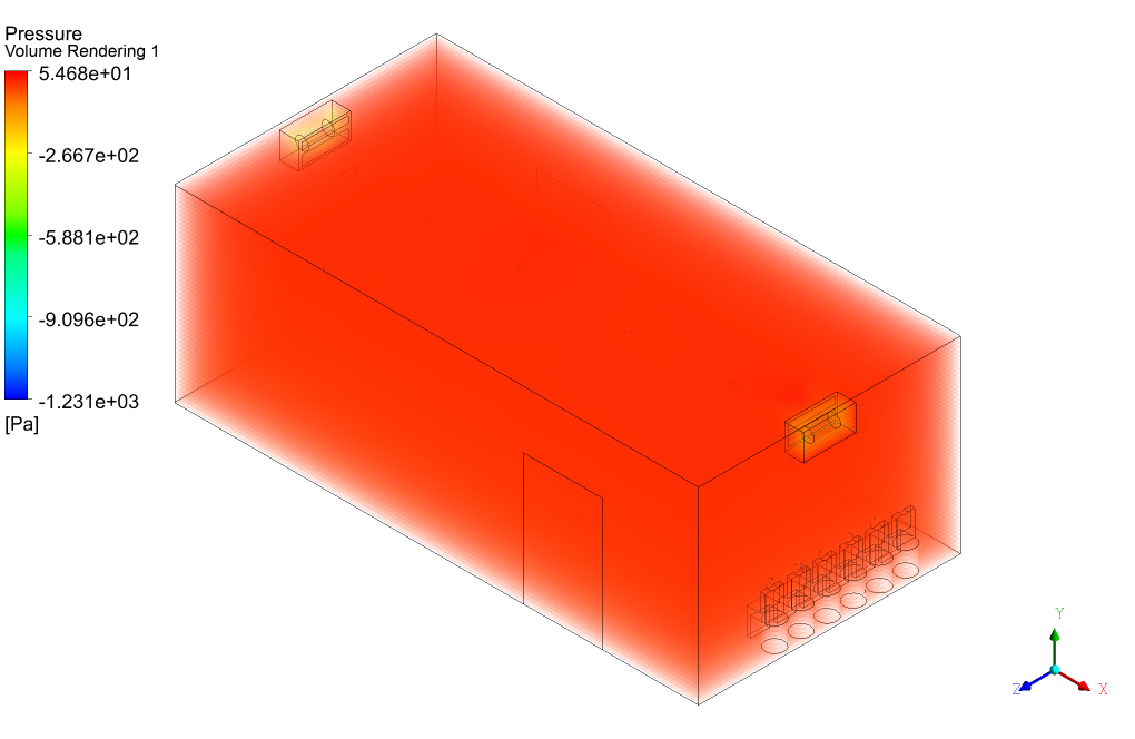
- In this project, the HVAC inside a room considering equipment and people is investigated by ANSYS Fluent software, applying two splitters with fans.
- The 3-D geometry of the present model is carried out using Design Modeler software.
- The present mesh is done in ANSYS Meshing. The element number is 547820.
- It should be noted that the ideal gas equation is opted to capture the changes in the air density (buoyancy effect) due to temperature change.
- The fan pressure jump is defined as a polynomial function.
To Order Your Project or benefit from a CFD consultation, contact our experts via email ([email protected]), online support tab, or WhatsApp at +44 7443 197273.
There are some Free Products to check our service quality.
If you want the training video in another language instead of English, ask it via [email protected] after you buy the product.
Description
Split Air Conditioner for Room HVAC, ANSYS Fluent CFD Simulation Training
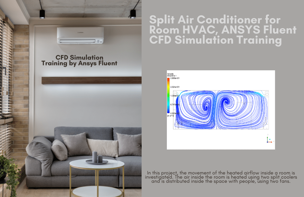
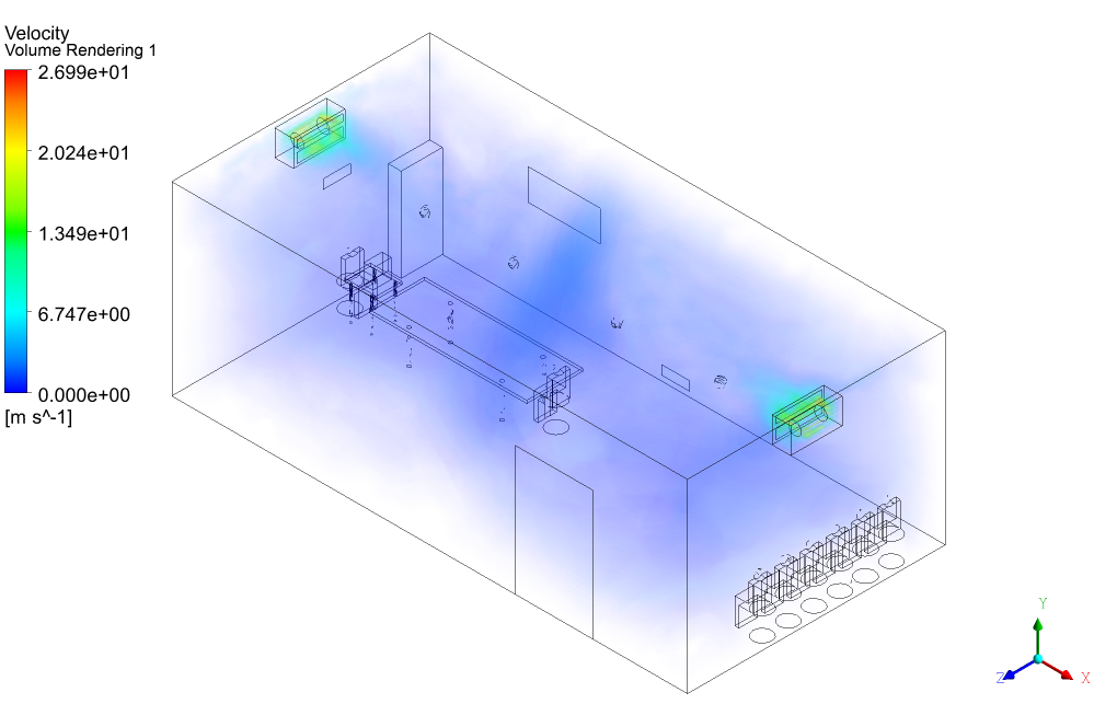
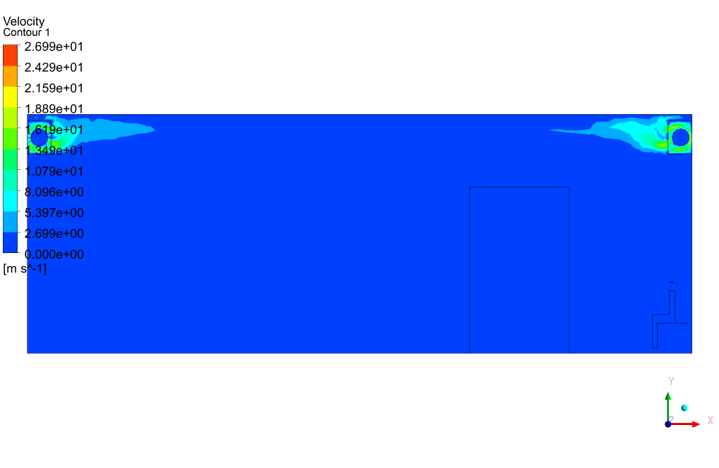
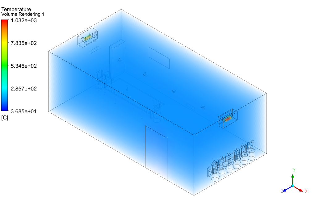
In this project, ANSYS Fluent software investigates the movement of the heated airflow inside a room. The air inside the room is heated using the Split Air conditioner for Room HVAC and is distributed inside the space with people using two fans. We perform this CFD project and investigate it by CFD analysis.
The geometry of this project is designed in ANSYS Design Modeler and consists of two split systems and office apparatus.
The present mesh is carried out in ANSYS Meshing. The mesh type used for this geometry is unstructured, and the element number is 547820.
CFD Methodology
A realizable k-epsilon model is exploited to solve turbulent flow equations, and the energy equation is activated to calculate the temperature distribution inside the computational domain.
It should be noted that the ideal gas equation is chosen to capture the air density changes due to temperature change and the consequent Buoyancy effect.
Split Air Conditioner for Room HVAC Conclusion
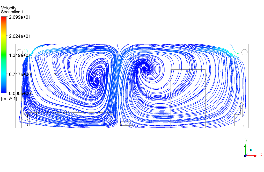
As was discussed about the movement of airflow due to the free convection and forced convection, the flow pattern and streamlines can be observed in streamlined contour.
The hot air will travel upward because of the decreased density (buoyancy effect). On its journey to higher room parts, it will gradually lose its temperature and fall. This systematic process will cause such flow patterns.


Christop Ankunding –
Your work is truly impressive. Keep it up!
MR CFD Support –
We appreciate your kind words! We’re glad you appreciate the quality of our simulations.
And so on… You can continue this pattern of comments and answers, alternating between praise and technical inquiries.
Prof. Rosendo Moen IV –
Very great. It is applied in the industry.
Toni Leffler –
Could you explain more about the phenomena you’re simulating in the Split Air Conditioner for Room HVAC CFD Simulation?
MR CFD Support –
Sure! This simulation models the airflow and temperature distribution in a room with a split air conditioner. It allows us to study and optimize the performance of air conditioning systems in different room layouts.
Lily DuBuque Sr. –
The intricacy in your simulations is commendable. Great job!
Dr. Adah Windler III –
How does the buoyancy effect influence airflow, and how well is this captured in the simulation?
MR CFD Support –
The buoyancy effect impacts the airflow significantly. In the simulation, the buoyancy causes warm air to travel upward as its density lowers, and then as it cools, it comes down again. This behavior is successfully captured in the simulation thanks to the use of the realizable k-epsilon model along with the energy equation to accurately track the air density changes with temperature.
Kenyatta Balistreri –
I am thoroughly impressed with the split air conditioner HVAC CFD simulation training. The visualization of airflow patterns helped me understand the practical aspects of HVAC design.
MR CFD Support –
Thank you for your kind words! We’re proud to hear that our training has enhanced your understanding of HVAC systems. Visualizing airflow is crucial for grasping these complex concepts, and we’re glad it was clear and valuable for you.
Danny Nader V –
The animations from this training gave a really clear picture of how convection affects airflow distribution in a room heated by an HVAC system. Fantastic visual learning tool!
MR CFD Support –
Thank you for your positive feedback! We’re pleased to know that our visual aids in the training were helpful in your learning experience.
Ari Conroy –
I love how thorough the CFD simulation is! The detailed setup, including the effect of the air conditioner and the fans on room airflow, helped me understand the convection process. The Buoyancy effect was especially interesting to read about, as well as the temperature gradients within the space.
MR CFD Support –
Thank you for your kind words! We’re thrilled to hear that the simulation was helpful and educational. It’s great to know that the details on convection and Buoyancy effects were insightful. We strive to provide accurate and comprehensive CFD simulation analyses, and your feedback is valuable to us.
Green Cormier –
The provided explanation on how airflow is circulated through the room was fantastic. Observing this dynamic process really helps me understand HVAC systems better. Well done!
MR CFD Support –
Thank you so much for your positive feedback! We’re delighted to hear that our simulation helped enhance your understanding of HVAC systems. It’s our goal to deliver comprehensive and clear insights into such processes. If you have any further questions or need additional information, please don’t hesitate to reach out.
Miss Simone Willms V –
The explanation of the airflow inside the room is fantastic. The simulation definitely helped me understand how the air moves due to the split air conditioner in a real environment.
MR CFD Support –
Thank you for your feedback! We’re thrilled to hear that our CFD simulation could provide valuable insights into the airflow patterns influenced by the split air conditioner. It’s great to know that our product enhanced your understanding of HVAC systems in real-world scenarios.
Maymie Ward V –
The Split Air Conditioner for Room HVAC CFD Simulation training was thoroughly informative. Your clear explanations made grasping the concepts of air movement and the effects of convection within a room setting much easier. Understanding the impact of split air conditioning systems, turbulence models, and airflow due to thermal gradients has practical applications. The visual outputs, especially the streamline contours demonstrating hot air rising and cooling, were particular highlights. Great insight and a valuable learning resource for anyone interested in HVAC systems!
MR CFD Support –
Thank you for your positive feedback! We’re thrilled to hear that you found the Split Air Conditioner for Room HVAC CFD Simulation training informative and practical. Visual cues, such as streamline contours, are indeed powerful in understanding complex systems and we’re glad you found them useful. If you have any further questions or need more insight into HVAC systems and CFD analysis, feel free to reach out. We are always here to help you with your learning and professional journey. Thanks again for choosing our training product!
Ayden Wisoky PhD –
The simulation visuals are incredibly helpful! The flow patterns really show how effective the split air conditioner design is within the room. It’s great to see heat distribution and airflow so clearly.
MR CFD Support –
Thank you for your positive feedback! We’re delighted to hear that you found the visuals and flow patterns informative and that the effectiveness of the split air conditioner design in optimizing room temperature was clear. We appreciate your compliments on the detailed presentation of the heat distribution and airflow. If there’s anything more we can assist you with, please let us know.
Emil Moore –
I never thought I could get a solid grasp on how room HVAC systems work until I went through this CFD training on a Split Air Conditioner. The visuals and flow chart patterns really helped make complex concepts understandable. Now I can appreciate the interplay between free and forced convection in room air distribution. Fantastic learning experience!
MR CFD Support –
We are thrilled to know that our CFD simulation training for the Split Air Conditioner HVAC helped clarify the concepts for you! Understanding the dynamics of airflow is vital, and we’re glad our visuals and materials aided in your learning. Thank you for taking the time to share your positive feedback!
Mrs. Jackie Deckow –
The training was amazing. I could follow along and now understand how airflow interacts in a room with an HVAC system!
MR CFD Support –
We’re thrilled to know you found the training amazing and that it enhanced your understanding of HVAC systems and airflow interactions. Learning how temperature and flow patterns change throughout a room is crucial for efficient design. Thanks for sharing your positive feedback!
Prof. Darlene Cummerata DDS –
I recently used the Split Air Conditioner for Room HVAC CFD Simulation learning product and I must say, I’m thoroughly impressed. The level of detail in the simulation is commendable, and it has given me an in-depth understanding of airflow dynamics due to convection processes. The streamlined contours provided a vivid picture of temperature distribution and air movement, enhancing my insight into HVAC system performance within an office environment. Exciting stuff!
MR CFD Support –
Thank you for your kind words! We are delighted to hear that our product has provided you with a comprehensive understanding of HVAC systems and helped enhance your knowledge of airflow and temperature distribution patterns. It’s our goal to offer detailed simulations that can provide valuable insights to our customers. If you have any more feedback or need further assistance, please don’t hesitate to get in touch!