
Darrieus Vertical Axis Water Turbine, Dynamic Mesh, ANSYS Fluent Training
$180.00 Internship
- The problem numerically simulates the Darrieus Vertical Axis Water Turbine using ANSYS Fluent software.
- We design the 3-D model with the Design Modeler software.
- We mesh the model with ANSYS Meshing software, and the element number equals 7422668.
- We perform this simulation as unsteady (Transient).
- We use the Dynamic Mesh Model to define the change of meshing around the rotating turbine blades.
- We define a Rigid Body by a rotational motion with one degree of freedom (1-DOF).
To Order Your Project or benefit from a CFD consultation, contact our experts via email (info@mr-cfd.com), online support tab, or WhatsApp at +44 7443 197273.
There are some Free Products to check our service quality.
If you want the training video in another language instead of English, ask it via info@mr-cfd.com after you buy the product.
Description
Description
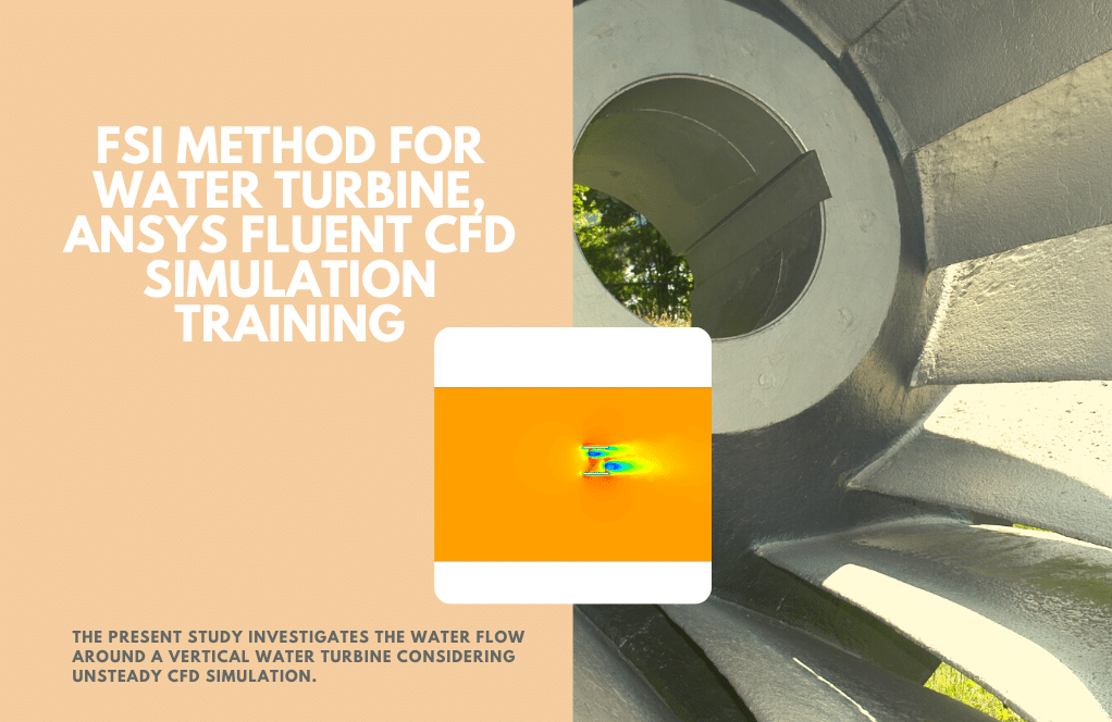
The problem simulates the water flow around a vertical axis water turbine (VAWT) submerged in water using the Dynamic Mesh method in ANSYS Fluent software.
The water turbine is from the category of vertical axis turbines and is of the Darrieus type, So the turbine’s axis is perpendicular to the direction of water flow.
For this simulation, a vertical axis turbine with three blades is designed within a relatively large computational area in which the computational area has only water flow.
The boundary conditions are also defined in such a way that the incoming water flow enters the computational domain with an average flow velocity of 1 m/s in the direction of the horizon (x-axis). The water flow exits the computational domain with a pressure equal to atmospheric pressure.
We design the present model in three dimensions using Design Modeler software. The model includes a computational domain, and we design a water turbine within this domain.
A darrieus-type water turbine is a category of vertical axis turbines. This turbine has three blades with a height of 0.5 m. This computational area is defined so that the center of the turbine is 3 m far from the inlet section, 10 m from the outlet section, and 0.75 m from the top and bottom surfaces.
We carry out the meshing of the model using ANSYS Meshing software, and the mesh type is Hybrid. Thus, the meshing in the areas around the turbine body is unstructured and structured in other areas of the model. The element number is 7422668.
Darrieus Methodology
In this simulation, it is assumed that the vertical turbine is rotating in the water flow, and therefore, this rotational motion of the turbine blade body affects the surrounding meshing. Therefore, the dynamic mesh model defines the change of meshing around the rotating turbine blades.
To better define the dynamic mesh, a cylindrical area is separated from the entire computational domain so that this area includes the turbine blades. Now, to define the areas under the dynamic mesh, the walls of the turbine blade body and the differentiated area around the turbine blades are defined as Rigid Bodies.
Two methods can be used to define the motion with several degrees of freedom for turbine blades; You can either use a UDF to define this motion, or you can define it manually in fluent software. Since this current model is a turbine, it only has a rotational motion, and on the other hand, this rotational motion can only take place around an axis.
Therefore, to define the type of motion of a rigid body, a rotational motion with one degree of freedom (1-DOF) should be specified; Thus, the mass of the blades was considered equal to 1 kg, and the moment of inertia of the blades was considered equal to 3.09 kg.m2.
The symmetry-type boundary condition also defines the upper and lateral surfaces of the computational area.
Due to the main nature of the model based on the use of dynamic mesh, the simulation process should be defined as Transient (Unsteady) that in the present model, the simulation process is performed in 50 seconds with a time step of 0.05 seconds.
Darrieus Conclusion
At the end of the solution process, we obtain two-dimensional contours relating to velocity, pressure, and kinetic turbulence energy, as well as path lines and velocity vectors on a plane passing through the center of the turbine. Turbine Torque and other turbine performance characteristics are also analyzed.
Reviews
You must be logged in to post a review.
Virginia Goyette –
Can this simulation predict the power output of the turbine?
MR CFD Support –
Yes, our simulation can provide detailed information on the power output of the turbine, which is a key factor in evaluating the performance of the turbine.
Marilie Boyer –
How are the boundary conditions set up in this simulation?
MR CFD Support –
The boundary conditions in this simulation are set up to replicate a real-world scenario. The inlet and outlet of the flow domain are specified with a certain flow velocity and pressure.
Marlon Hegmann –
I’m curious, do the results include any data on how much energy the turbine is able to extract from the water flow?
MR CFD Support –
Yes, the results of the simulation include an analysis of turbine performance characteristics, which typically involve calculating the torque produced by the turbine. By analyzing this torque and the rotational speed, an estimation of the extracted energy can be made. These performance metrics are crucial in evaluating the efficiency of the turbine.
Dr. Haylie Reinger III –
The product description is rather comprehensive but doesn’t mention if the influence of different water densities was considered for the turbine performance. Can the simulation evaluate the effect of varying water densities on the turbine’s efficiency?
MR CFD Support –
In this particular simulation using ANSYS Fluent software to model the Darrieus Vertical Axis Water Turbine, variations in water density are not explicitly mentioned in the setup. Nevertheless, ANSYS Fluent does have the capability to simulate the effect of different fluid densities on the performance of the turbine through material property settings and multiphase flow models, if necessary. If your study requires understanding the impact of varying water densities, such as in different temperatures or salinities, this factor could be included within the simulation parameters, and the appropriate adjustments to the model and boundary conditions would be made.
America Ankunding –
Thanks for the comprehensive training on Dynamic Mesh analysis in ANSYS Fluent! I’ve learned so much about simulating the Darrieus Water Turbine and the related dynamic mesh techniques. The inclusion of torque calculations and performance characteristics really helps understand the turbine’s efficiency.
MR CFD Support –
Thank you for your kind words! We’re thrilled to hear that you found the Darrieus Water Turbine simulation training informative and useful. It’s great to know that the torque calculations and performance analysis added valuable insight into the efficiency of the turbine. Your satisfaction is our priority and we strive to provide quality learning content. Thank you for choosing our product for your learning needs!
Ms. Alaina Wilkinson –
Can this simulation be used to optimize the design of the turbine?
MR CFD Support –
Absolutely, this simulation can be used as a tool for design optimization. By changing the design parameters of the turbine and observing the resulting behavior, you can identify ways to improve the design of the turbine.
Dr. Vincenza Bayer DVM –
Can you detail how the rotational motion for the blades was set up in the Fluent software?
MR CFD Support –
In Fluent, the rotational motion of the turbine blades is set by defining a single degree of freedom (1-DOF) rotational motion parameter for the rigid body which includes the blade walls. To accomplish this setup, parameters such as the mass and moment of inertia of the blades are specified. Typically, these parameters allow Fluent Dynamic Mesh feature to calculate how the mesh needs to adapt as blades rotate with respect to the designated axis.
Cora Braun DDS –
I found the explanation about setting up the dynamic mesh for the points interesting around the turbine blades intriguing. Could you detail how to extract turbine torque data from these simulations?
MR CFD Support –
The turbine torque in these simulations is typically calculated based on the forces exerted by the fluid on the rotating blades. This data is extracted by integrating the moment of the force around the axis of rotation, considering the distribution of pressure and shear stress on the blades. ANSYS Fluent allows you to monitor this value during the simulation through the Reports -> Forces option. You can set it to record torque at each time step and subsequently use this data to evaluate the turbine’s performance.
Prof. Dena Langworth IV –
My compliments on your detailed Darrieus Vertical Axis Water Turbine course. The depth and quality of material provided were excellent, making the learning experience intuitive and fulfilling. I especially appreciated the understanding it provided on dynamic meshing within ANSYS Fluent. The graphics and results interpretation have substantially clarified my grasp of turbine simulation and analysis. Looking forward to more immersive courses like this.
MR CFD Support –
Thank you for your thoughtful review! We are delighted to hear that the Darrieus Vertical Axis Water Turbine course met your educational needs and provided clear and comprehensive insights into the complex field of CFD simulation with dynamic meshing capability in ANSYS Fluent. Your satisfaction is our primary goal, and we look forward to continuing to serve you with great content in the future. If there’s any particular subject area or additional simulation type you’re interested in, please let us know!
Jany Bergnaum –
I found the section on the rotational motion of the turbine blades really interesting. Could you explain a bit more about how the rotational motion is calculated and its impact on the surrounding water flow?
MR CFD Support –
In this simulation, the rotational motion of the turbine blades is calculated based on the set boundary conditions and the physical properties such as the mass and moment of inertia of the blades. The impact of this rotation on the surrounding water flow is accounted for using the Dynamic Mesh method, which allows the mesh to adapt to the movements of the blades, thus capturing the interactions between the rotating turbine and the fluid flow more accurately.
Herta Lowe IV –
The VAWT simulation sounds fascinating! Could we check the torque output trend over time for operational optimization purposes?
MR CFD Support –
Absolutely! The analysis includes tracking the turbine’s torque output over time, which is fundamental for assessing performance and optimization. The results from the transient simulation provide insights into the torque generation pattern, supporting efforts to optimize the turbine’s operation.
Warren Stark –
I’ve been thrilled with the detailed insights provided. Could the team clarify if the simulation accounts for turbine torque fluctuations over time, and how this impacts the overall efficiency analysis?
MR CFD Support –
Yes, the simulation will capture the fluctuations in the turbine torque over time as it falls under the transient dynamic simulation, which inherently tracks the changes in forces and momentums over the simulation’s time steps. These fluctuations directly influence the efficiency analysis, allowing us to assess the performance of the turbine under varying flow conditions. The outcome of these analyses will typically involve calculating averages and identifying patterns which help estimate the overall turbine efficiency in realistic operational conditions.
Jacquelyn Purdy DVM –
I was impressed by the clarity and depth of the information provided on the Darrieus Vertical Axis Water Turbine training. The step-by-step explanation of the methodology enhanced my understanding of dynamic mesh applications in CFD significantly. Well done on such a comprehensive tutorial!
MR CFD Support –
We are thrilled to hear that our Darrieus Vertical Axis Water Turbine training material has provided you with a valuable learning experience! Your appreciation of the detailed explanations affirms our commitment to offering high-quality CFD tutorials. Thank you for choosing our company as a source for your educational journey. If you have any more questions or need further clarification, don’t hesitate to reach out to us.
Bailee Kertzmann –
What type of dynamic mesh settings did you employ for simulating the rotational motion of the Darrieus water turbine blades?
MR CFD Support –
In the simulation of the Darrieus water turbine, the dynamic mesh settings involve defining the area surrounding the rotating blades as a rigid body. This allows the mesh to adapt as the blades rotate. The blades themselves are designated within this rigid body and a rotational motion with one degree of freedom (1-DOF) is specified. The mesh update method likely uses both remeshing and smoothing to accommodate the rotation of the turbine blades. Moving boundaries are controlled through User-Defined Functions (UDF) or preset motion conditions in the software to accurately capture the interactions between the rotating blades and the water flow.
Barry Dach –
The product’s focus on the dynamic mesh methodology is exactly what I was looking for! It helped me understand the complexities involved with simulating rotational movement in fluid dynamics.
MR CFD Support –
Thank you for your positive feedback! We are thrilled to hear our dynamic mesh methodology training provided you with a clear understanding of simulating rotational movements in fluid dynamics. If you need any further assistance or have more questions in the future, feel free to reach out!
Brody Rohan –
Great detail in the methodology, but could you elaborate on how the UDF is specifically used within this simulation?
MR CFD Support –
The UDF (User-Defined Function) in this simulation would be used to define the customized rotational motion of the turbine blades. It provides the precise dynamics required which may not be readily available within the standard functions of ANSYS Fluent. In particular, the UDF defines the angular velocity or position as a function of time, ensuring that the mesh updates correctly as the turbine rotates dynamically during the simulation.
Freddy Huels –
I am impressed by how comprehensive the Darrieus Vertical Axis Water Turbine CFD simulation training is! The dynamic mesh aspect and transient analysis seem to be particularly well detailed. Thank you!
MR CFD Support –
Thank you so much for your positive feedback! We’re delighted you found the Darrieus Vertical Axis Water Turbine CFD simulation comprehensive and informative. If you have any questions or need further assistance, feel free to reach out.
Ms. Opal Gulgowski –
The training for the Darrieus Vertical Axis Water Turbine simulation has sparked my curiosity in customizing to different types of flows. Can you guide me on how to adapt the dynamic mesh and rotational settings to accommodate a slower stream with intermittent flow patterns?
MR CFD Support –
Adjusting the dynamic mesh and rotational settings for different flow conditions involves tweaking velocities and time step settings. In your scenario with a slower intermittent flow, it’s important to change the average flow velocity to match your stream’s speed and gradient. Also, refining the time step to smaller increments can improve the accuracy of capturing the intermittent flow patterns. For the dynamic mesh, check if the interactions between the blade rotations and the fluctuating flows require modifications to the remeshing parameters.
Suzanne Bernier –
I am very impressed with the detailed results from the Darrieus VAWT CFD simulation. What performance characteristics of the turbine were assessed in the analysis?
MR CFD Support –
We’re glad you’re pleased with the simulation outcome! In the analysis, the turbine’s torque was meticulously examined, along with other performance characteristics such as power output, efficiency, and the impact of blade rotation on the surrounding water flow.
Jamel Stiedemann –
I’m curious about the use of dynamic mesh with the rigid body in this context. How is the rotational movement of the blades integrated with the dynamic mesh update during the simulation?
MR CFD Support –
The rotational movement of the blades is integrated using the dynamic mesh method to define the changing mesh around the rotating turbine blades. We specify the turbine blade walls and around them as rigid bodies using the Rigid Body option. For the turbine’s rotational motion, either a UDF could be utilized to specify the motion precisely, or manual settings within the Fluent software could be made. In this case, we precisely define a 1-DOF rotational motion around an axis that correlates with the actual physical rotation of the blades. The necessary mass and moment of inertia properties are inputted to capture the correct dynamics. Mesh update techniques like smoothing and remeshing keep the mesh quality manageable as the blades rotate. This integration makes sure the fluid-structure interaction is well-simulated, and the effect of the structure’s movement on the fluid domain is accurately captured in each time step.
Myron Kemmer –
What are the key outcomes of this type of simulation, regarding turbine performance?
MR CFD Support –
The outcomes of this simulation prominently include data related to turbulence, fluid-structure interaction, and the mechanical aspects impacting the performance of the water turbine. Velocity and pressure contours, kinetic turbulence energy, path lines, and velocity vectors around the turbine are also valuable for assessing performance. Turbine torque, power generation estimates, and overall efficiency of the system are the key performance indicators analyzed.
Dr. Amber Weissnat –
How does the Dynamic Mesh model update the mesh around the rotating turbine blades without causing mesh quality issues during the simulation?
MR CFD Support –
In this simulation, the Dynamic Mesh model ensures the appropriate mesh quality during blade rotation by separating a cylindrical area that includes the turbine blades and defining this area under dynamic mesh controls. It employs the methods of Smoothing and Remeshing: ‘Smoothing’ adjusts mesh node positions to maintain quality without altering the connectivity, while ‘Remeshing’ creates and deletes cells as necessary to accommodate shape changes in the rotating bodies. If any localized mesh distortion occurs, the dynamic mesh algorithm is designed to correct it considering the rotation motion.
Alia Upton –
The tutorial was really detailed, and I feel confident about understanding dynamic meshes now. The visualizations helped a lot in understanding the fluid flows around the turbine. Great work!
MR CFD Support –
Thank you for your positive feedback! We’re delighted to hear that our tutorial on Darrieus Vertical Axis Water Turbines using Dynamic Mesh was helpful and made the concept easier to understand. It’s gratifying to know that the details and visualizations were effective tools for your learning experience. We strive for clarity and thoroughness with all our training content. If there are any more topics you’re interested in, or if you have further questions, please feel free to reach out!
Ms. Danielle Lynch –
The product breakdown was so well-explained and detailed! I had a fantastic time learning from the training materials and found it easy to follow along with the steps for simulating the Darrieus Vertical Axis Water Turbine. The provided images and the methodology descriptions were incredibly helpful for visualizing the process. The section on Dynamic Mesh was particularly interesting—seeing how the mesh adapts to the rotating blades was enlightening. I gained new skills for my studies in fluid dynamics, all thanks to MR CFD’s comprehensive training kits. Fantastic job!
MR CFD Support –
We’re absolutely delighted to hear that you found the training material thorough and easy to follow! Your positive feedback on the Darrieus Vertical Axis Water Turbine simulation is greatly appreciated. It’s a pleasure to know our detailed explanations, images, and methodology helped you in your fluid dynamics studies. Thank you for choosing our product, and we look forward to providing you with more quality learning experiences in the future!
Ricky Lueilwitz PhD –
The text mentions using either a UDF or manual settings for the motion in fluent software, which method was actually used in this training for specifying the turbine’s motion?
MR CFD Support –
In this particular training, we manually defined the rotational motion of the turbine with one degree of freedom (1-DOF) in ANSYS Fluent, rather than using a UDF. The mass and moment of inertia for the blades are provided to fluent, and the simulation is conducted accordingly.
Ms. Ara Vandervort –
The dynamic mesh model changed based on the rotational motion of the turbine blades, but I am curious about how did you control or track the changes in the mesh over time during the simulation?
MR CFD Support –
In the simulation of the Darrieus Vertical Axis Water Turbine, dynamic mesh motion is controlled using Fluent software’s ability to handle dynamic meshes. The motion of the blades is either predefined using a User-Defined Function (UDF) that specifies the blade rotation or set manually to reflect the desired degree of freedom, such as rotational motion. During the numerical solution process, Fluent adjusts the local grid cells continuously by using mesh smoothing and re-meshing techniques, so that a high-quality mesh is maintained around the moving parts of the turbine—for this simulation, the rotating blades. The computation takes place in discrete time-steps (0.05 seconds here), and after every time step, the mesh is updated to capture the new position of the blades. The variation in the mesh through simulations can be monitored by extracting and visualizing data on geometry and mesh quality at different intervals.
Maximo Wilkinson –
Your dynamic mesh tutorial on the Darrieus Vertical Axis Water Turbine was incredibly helpful. The step-by-step instructions made the complex process understandable and the visualization of results was amazing.
MR CFD Support –
Thank you for your kind words. We’re delighted to hear that our tutorial on the Darrieus Vertical Axis Water Turbine using dynamic mesh in ANSYS Fluent has been helpful for you! We put a lot of effort into making complex subjects understandable and are glad it’s appreciated. If you have further inquiries or need more guidance, feel free to reach out to us.