DeltaT Macro, UDF, Time Step Control CFD Simulation
$120.00 Student Discount
- The problem numerically simulates the water filling in the tank using ANSYS Fluent software.
- We design the 2-D model with the Design Modeler software.
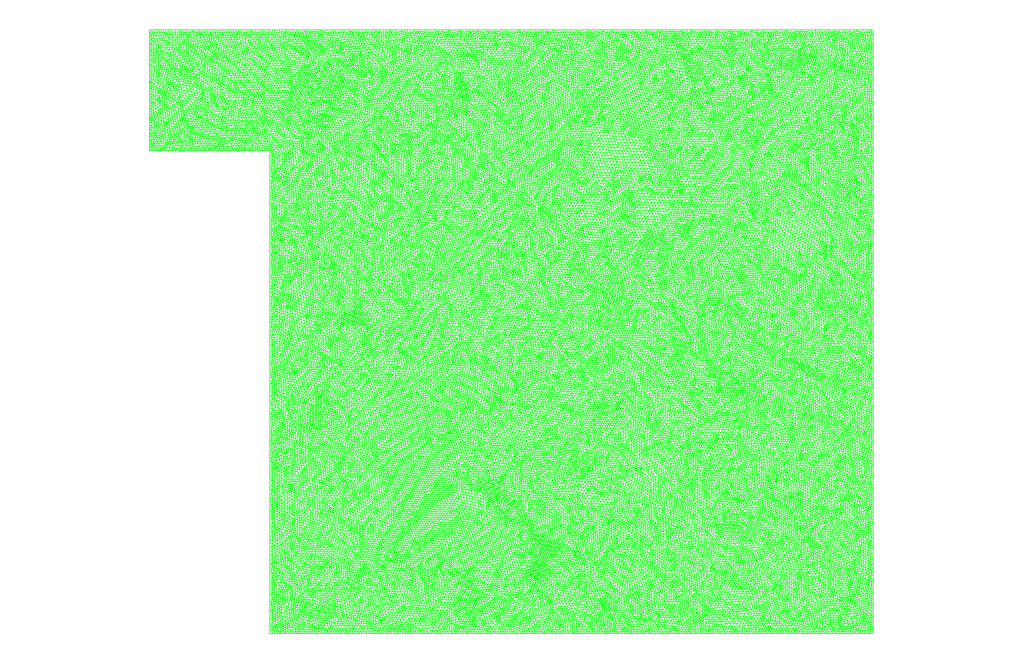
- We mesh the model with ANSYS Meshing software, and the element number equals 135996.
- We performed the simulation in a Transient (unsteady state).
- We use the VOF Multiphase model to define water and air.
- We use the User-Defined Function (UDF) to control time step size.
- We use the DELTAT Macro for UDF.
To Order Your Project or benefit from a CFD consultation, contact our experts via email ([email protected]), online support tab, or WhatsApp at +44 7443 197273.
There are some Free Products to check our service quality.
If you want the training video in another language instead of English, ask it via [email protected] after you buy the product.
Description
Description
In this project, we performed a numerical simulation using a User-Defined Function (UDF) by ANSYS Fluent software. For this CFD product, we used DeltaT Macro to write UDF programming.
This product is the 4th chapter of the User-Defined Function (UDF) Training Course.
We considered a simple tank where the water flow enters the tank from the inlet opening on the top of the tank. The purpose of this problem is to fill the tank over time.
Since this problem is solved as time-dependent, we performed the current simulation in an unsteady (Transient) state. So for calculations, we need to define the Time Step size. To determine the size of the time step, you must pay attention to one crucial note.
As the time step size becomes smaller, it strengthens the solution’s convergence and increases the solution’s accuracy significantly. But this creates a severe problem. The smaller the time step size, the longer the calculation process, and hence the computational cost of the modeling increases.
If the time step size becomes larger, it increases the solution’s speed and reduces the computational cost. However, the problem is that this work leads to a decrease in the accuracy of the solution or even an increase in the possibility of disruption in the convergence of the solution.
Therefore, in many problems, such as the current simulation where the existence of multiphase flow makes the calculations heavy, we need to control the time step size. Professional CFDs start the solution process with a very small time step size to establish initial convergence and stability.
Then, after ensuring the necessary stability and convergence, step by step and gradually increase the time step size to increase the speed of the solution. But this may be boring. So we intend to provide a better method.
In the first step, we modeled the geometry in 2D with Design Modeler software.
In the next step, we meshed the model with ANSYS Meshing software. Meshing is unstructured, and 135,996 cells are created.
Methodology (UDF)
In this project, we need to define two different phases. At first, the tank is filled with air, and gradually the water flow enters the tank. Then we used the Multiphase model. Since the two phases don’t mix and the separation boundary between the two phases is distinct, we used the Volume of Fluid (VOF) model.
Also, as we said, we intend to control the time step size. So we used a User-Defined function (UDF) to control the time step. We need to use the DeltaT Macro (DEFINE_DELTAT macro) for this UDF.
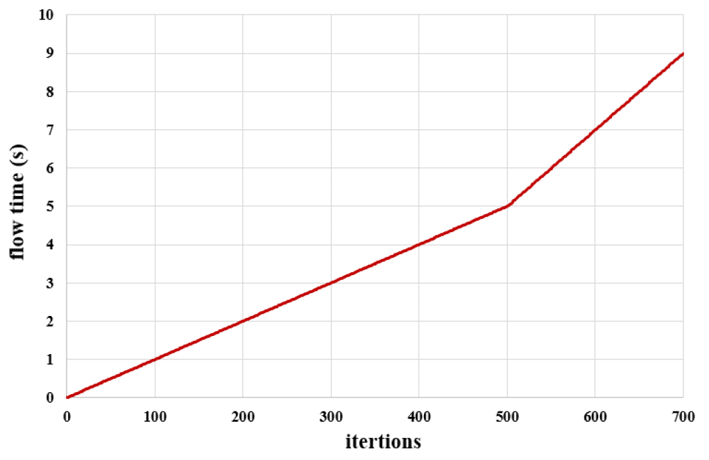
We ran the calculation for 9 seconds. For this, we use 700-time steps. Before the 5th second, we define the time step size as 0.01 second, and after the 5th second, we increase the time step size to 0.02 second.
Conclusion (UDF)
After completing the calculation, we will review the results. At first, we presented the plot of flow times per time step number. This modeling has been done in 700 time steps. Up to the time step of 500, the time step size equals 0.01 seconds. So the flow time goes up to 5 seconds.
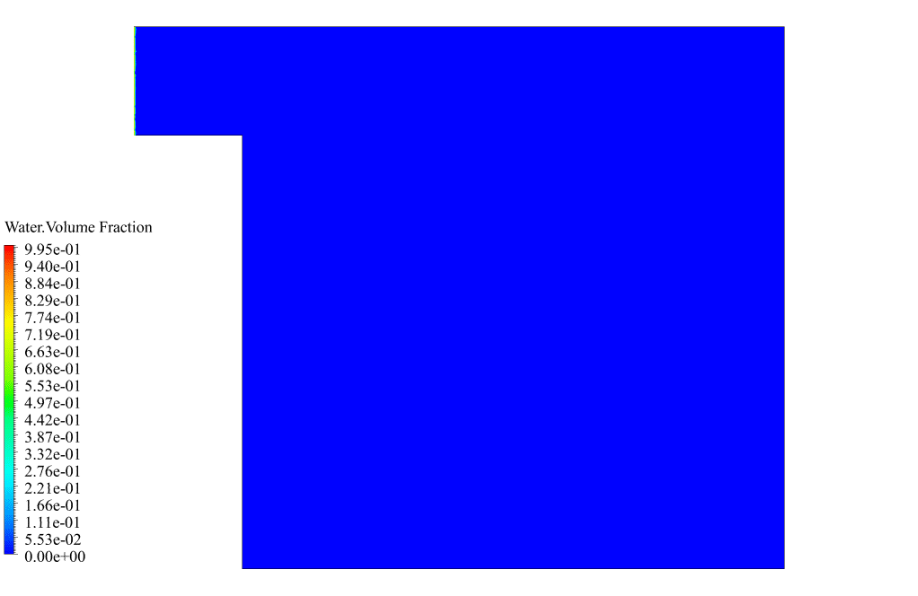
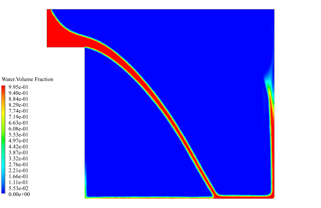
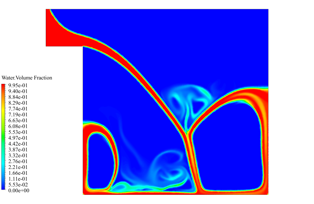
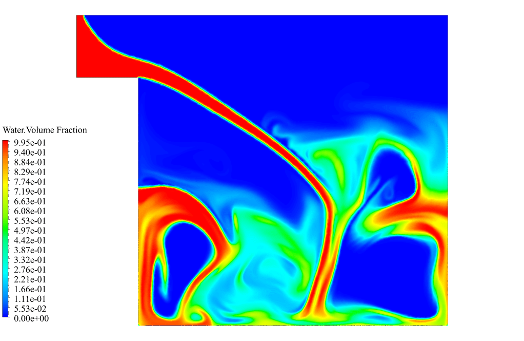
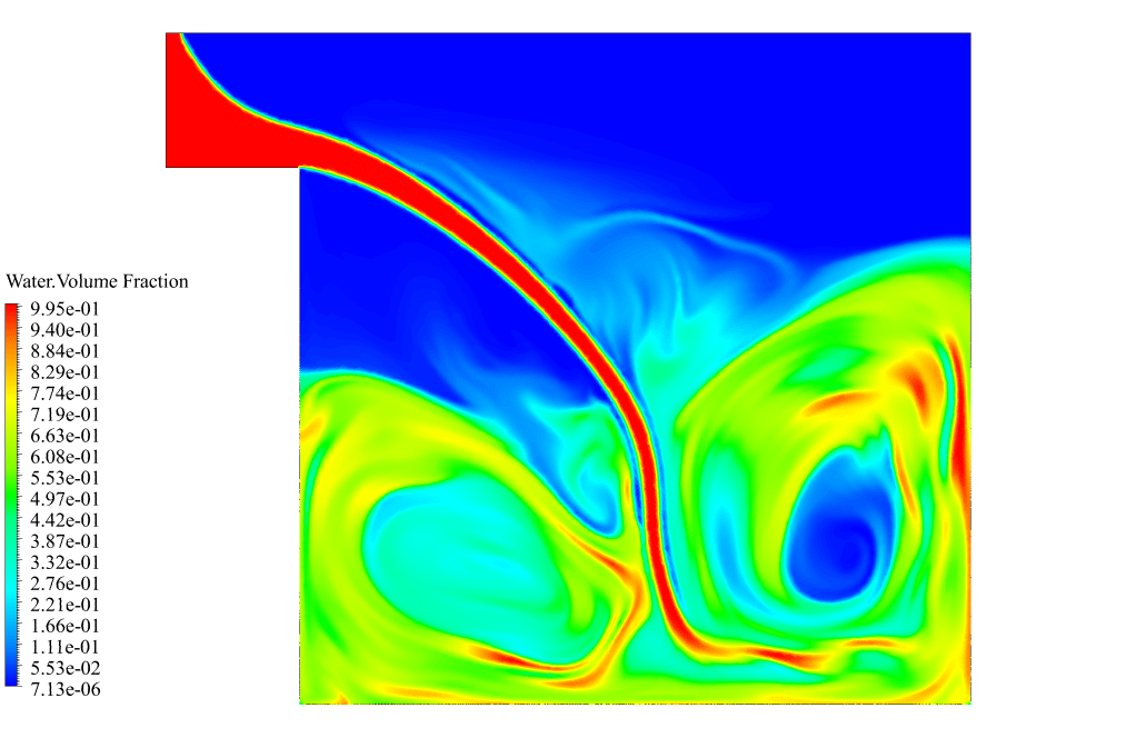
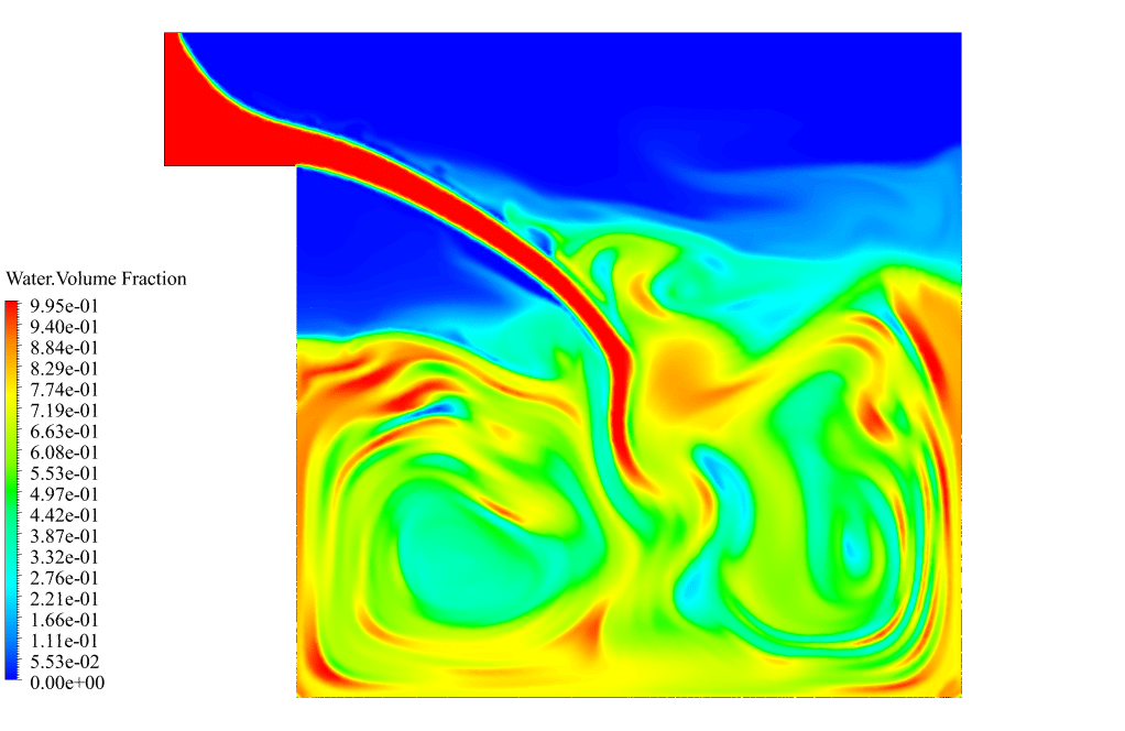
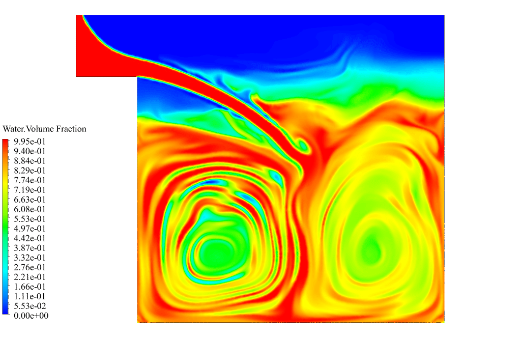
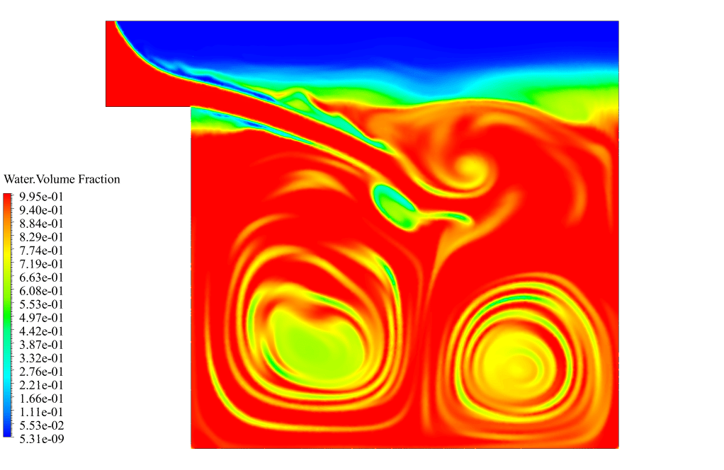
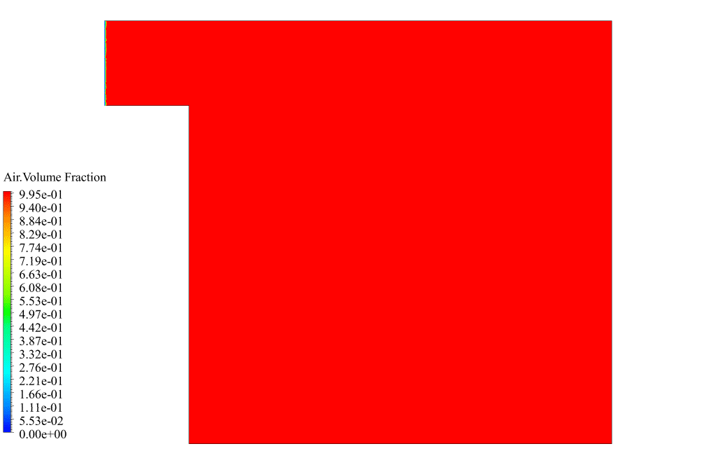
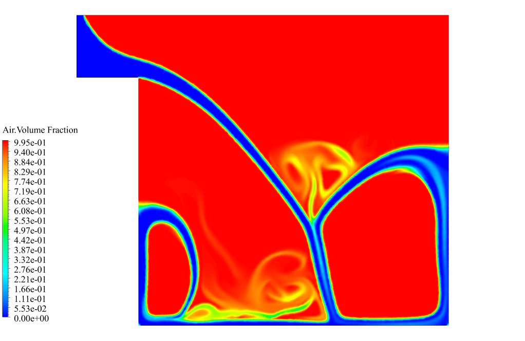
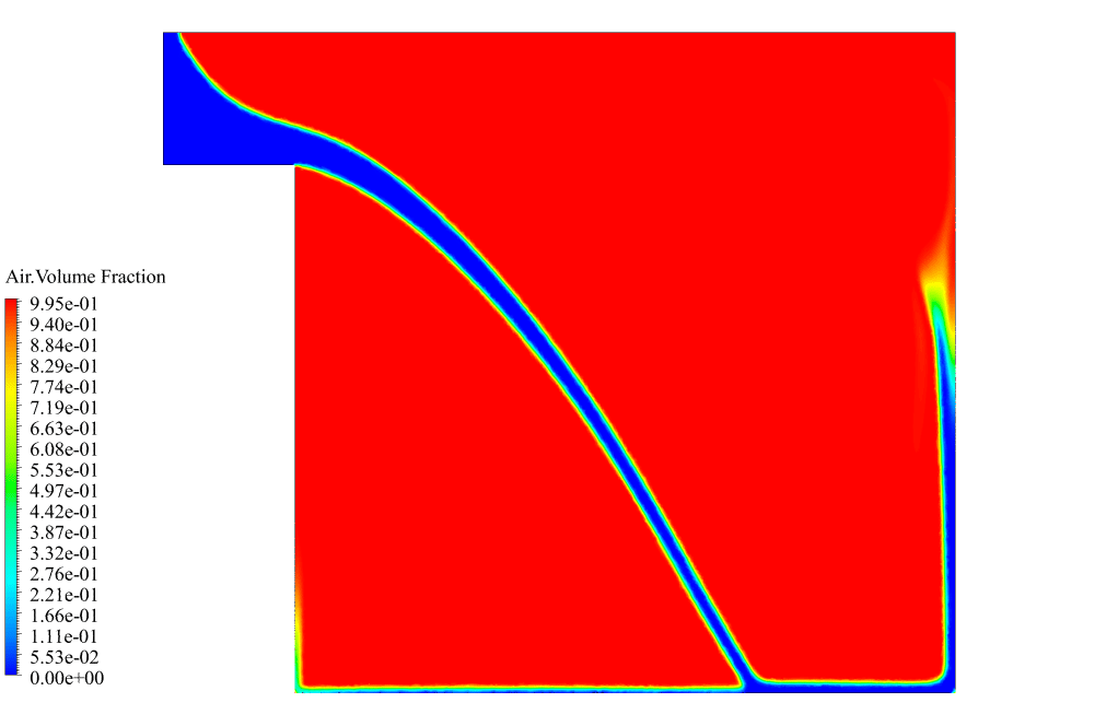
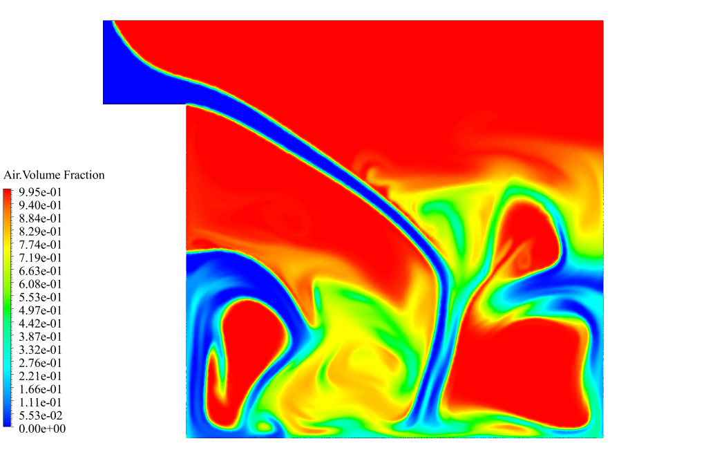
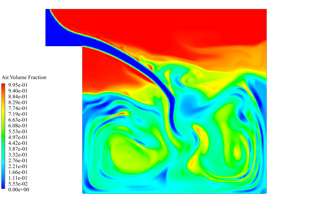
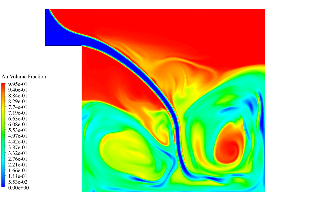
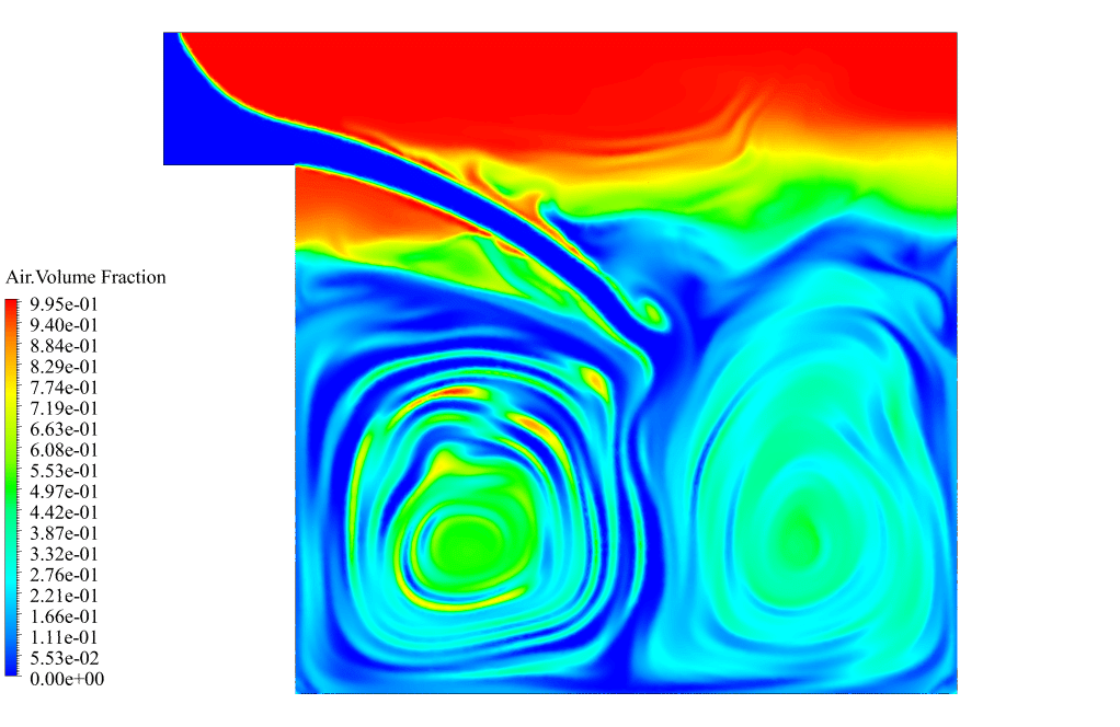
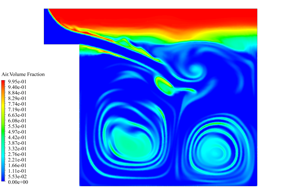
After that, the time step size is equal to 0.02 seconds. So the flow time goes for 4 seconds. This plot correctly shows this time step increase. That is, from the 5th second, the gradient of the flow time increases. We also obtained some contours to show the filling of the water tank. So, we obtained the contours of air and water volume fractions at different simulation times.
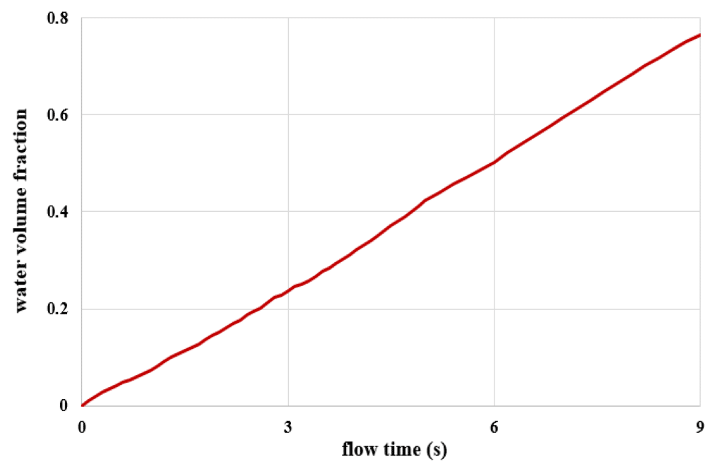
The contours show that the water phase inside the tank is increasing, and the air phase inside the tank is decreasing. It means that the process of filling the tank is occurring. We also obtained the plot of water volume fraction changes according to flow time. This plot also shows the filling of the water tank.



Ms. Lindsay Kreiger –
The UDF for controlling the time step size seems like an efficient way to ensure solution stability and speed. Does the use of DeltaT Macro affect the system’s overall computational load significantly, or is it optimized to manage the computational resources effectively?
MR CFD Support –
Using the DeltaT Macro within a UDF for controlling the time step is an efficient way to balance accuracy and computational resource utilization. The computation load often increases with smaller time steps due to the greater number of iterations; however, with proper use of DeltaT Macro to adjust time step size dynamically in response to simulation demands, the system can optimize computational resources. The goal is to start with smaller steps for initial stability and then increase the step size gradually, which helps manage the overall computational load effectively throughout the simulation.
Adelia Langosh –
Can you explain how the UDF helps in controlling the time step size more clearly?
MR CFD Support –
The UDF (User-Defined Function) in this simulation is utilized to dynamically adjust the time step size during the simulation process. By using the DEFINE_DELTAT macro, the UDF allows you to change the time step size according to custom logic. In this case, the UDF is programmed to start the simulation with a smaller time step size for higher resolution and stability, and after the 5th second, it increases the time step size, which helps in speeding up the simulation without significantly affecting the accuracy. This strategy is especially useful in multiphase simulations like this one, where the initial phase of the process may require more precision to establish initial convergence.
Lizeth Rolfson –
What a fantastic way to integrate UDFs for time step control in simulations! The ability to influence time step size dynamically allows for both precision and efficiency. Can’t wait to apply this in my own CFD projects!
MR CFD Support –
We are thrilled to hear that you’re excited about applying our UDF method for time step control! Thank you for the compliments on our DeltaT Macro feature. If you have any questions as you implement this in your projects, feel free to reach out. Happy simulating!
Rosetta Farrell –
Can this DeltaT UDF method for time step control be utilized in other simulations that involve phase change or only for multiphase flow like in this water tank example?
MR CFD Support –
Yes, the DeltaT UDF method for controlling the time step size can be employed in a variety of simulations that require time step adjustment, including those involving phase change. It is especially useful when dealing with transient simulations where the conditions vary greatly over time, and precise control over the time step can significantly improve convergence and accuracy.
Flossie Reichel –
Some of the UDF concepts aren’t clear to me. Could you explain what defines the DeltaT Macro and its role in the time step control for the simulation?
MR CFD Support –
The DeltaT Macro is a User-Defined Function (UDF) feature in ANSYS Fluent that allows you to programmatically adjust the time step size during a simulation based on specified criteria. This macro is used to enhance the efficiency of unsteady simulations by initially using a small time step for stability and convergence, and then increasing it once the solution has stabilized to expedite the overall simulation time. This approach can improve computational speed without compromising the accuracy of the results dramatically.
Francisca Little –
I thoroughly enjoyed learning from the UDF Training Course. It was great to apply UDF to control the time step size – truly a practical skill for my projects. It was particularly enlightening to see how initial stability was achieved with a small time step and later the step size was increased to expedite the simulation. Very useful technique!
MR CFD Support –
Thank you for your positive feedback! We’re thrilled to hear that the UDF Training Course was instrumental in enhancing your simulation projects. It sounds like the skill of time step control will serve you well in future analyses. If there’s more we can do to support your continued learning, please let us know.
Benjamin Kovacek –
This UDF method to control the time step size seems efficient; could you tell me when exactly we should consider switching to a larger time step to optimize computation without hampering result accuracy?
MR CFD Support –
Typically, a larger time step is considered after establishing initial convergence and stability. In the provided simulation, for instance, the transition to a larger time step was made after 5 seconds, coinciding with reaching a stable phase of the simulation. This ensures computational efficiency while maintaining result accuracy.
Prof. Edgardo O’Hara MD –
Does the use of the DELTAT Macro in the UDF allow for automatic time step adjustment during the simulation or does it have to be manually set based on the progress of the simulation?
MR CFD Support –
In this product, the DELTAT Macro in the UDF is programmed to increase the time step size after a specific simulation time (5th second) automatically. This adjustment does not require manual setting during the simulation but it requires the initial setting up of the UDF with the specific conditions for when the time step change should occur.
Dr. Adrianna Armstrong –
Excellent tool for learning! The implementation of a UDF to control time step sizes seems very well thought out. This must help in intricate simulations, providing stability and accuracy when you need it, and speed once the calculation has stabilized. A very educational CFD example from MR CFD on efficient time step control strategies. It shows how crucial fine control can be in multi-phase simulations. Besides, using a UDF to automate the process saves so much time and possibly avoids human error. Great work!
MR CFD Support –
Thank you for your positive feedback! We’re thrilled to hear that you found the DeltaT Macro UDF and the time step control methodology educational and beneficial for conducting efficient CFD simulations. At MR CFD, we continuously strive to provide intelligent solutions to complex problems, and your acknowledgement reinforces our commitment to excellence. Your satisfaction motivates us to keep creating high-quality learning products. If you have further insights or need more assistance, don’t hesitate to reach out.
Brice Greenfelder Sr. –
This product really clarified the use of UDF and DeltaT Macro for me! I was particularly impressed with how the dynamic time stepping was implemented to balance solution accuracy and computational cost. Your example provides a clear, practical application that aids in understanding the theory behind time step control.
MR CFD Support –
Thank you for your positive feedback! We’re thrilled to hear that our DeltaT Macro UDF product has been helpful in enhancing your understanding of time step control in CFD simulations. It’s our goal to provide educational materials that are both informative and practically applicable. We appreciate your support and are here to assist you if you have any more questions or need further clarification in your learning journey.
Nona McCullough –
Is the DeltaT Macro UDF method more efficient than manually adjusting the time step for all simulations, or is it case-specific?
MR CFD Support –
The DeltaT Macro UDF method serves as an efficient way to automatize the process of time step adjustment, particularly for cases that require an initial smaller time step that can be increased as the simulation proceeds to achieve a degree of stability. However, the suitability and efficiency of this method can be case-specific; it may be more beneficial in complex, multiphase simulations where manual adjustments can be tedious and error-prone. Whether it is more efficient than manual adjustments depends on the computational resources and the accurate prediction of varying time steps suited for each stage of the simulation.
Jettie Kulas –
The approach in using UDF with DeltaT Macro for controlling time step size is intriguing. Can you explain how the DeltaT Macro dynamically adjusts the time step during the simulation?
MR CFD Support –
Absolutely, the DeltaT Macro within the UDF is designed to adjust the time step size dynamically as required based on predefined criteria. During the simulation process, it initially sets a small time step to ensure the convergence and stability are established. Once the simulation exhibits stable convergence, and as the solver progresses, the macro then incrementally increases the time step size after the 5th second from 0.01 to 0.02 seconds to accelerate computation. This strategy balances the trade-off between accuracy and computational efficiency.
Mrs. Alvina Pfeffer PhD –
I really enjoyed learning about time step control with the DeltaT Macro UDF as covered in chapter 4. The balance between computational cost and solution accuracy is crucial and this provided a practical perspective on managing it.
MR CFD Support –
We’re thrilled to hear that you found the DeltaT Macro UDF simulation valuable and enlightening. Understanding the time step control trade-offs between computational cost and accuracy is indeed an essential skill in CFD analysis, and we aim to provide effective learning tools for this purpose. Thank you for your feedback and for choosing our UDF Training Course to enhance your knowledge.
Kayden Crona –
Love how DeltaT Macro is applied to control the time step size in the simulation; it’s a smart approach to balance accuracy and computation cost.
MR CFD Support –
Thank you for the positive feedback on our DeltaT Macro feature and its role in time step control! We’re glad to hear that our efforts in enhancing simulation efficiency resonate well with you.
Dr. Orval Jones –
The UDF for DeltaT Macro sounds impressive! How does it adapt the time step size during the calculation process and how does this benefit the outcome?
MR CFD Support –
The UDF uses the DEFINE_DELTAT macro to adjust the time step size dynamically during the calculation process. Starting with a smaller time step ensures initial convergence and stability, and as the simulation progresses and those conditions are met, the UDF increases the time step to speed up the calculations. This approach balances accuracy with computational efficiency.
Maxie Hahn IV –
This UDF tutorial is fantastic, and the DeltaT Macro is incredibly useful for optimizing simulation time without compromising accuracy. Keep up the good work!
MR CFD Support –
Thank you for your kind words! We’re delighted to hear that our DeltaT Macro UDF tutorial met your needs and helped in optimizing your simulation. We strive to provide valuable content to our users, and it’s rewarding to know we’re succeeding. If you have any more feedback or require further assistance, our team is always here to help. Thank you once again for choosing us for your CFD learning journey!
Warren Hegmann –
The review of DeltaT Macro UDF was very informative. Following your methodology made it easy to understand the benefits of UDF in controlling the time step size for enhancing stability and convergence during simulations. It’s fascinating how such adjustments can dramatically affect the speed and accuracy of the simulation results. Thank you!
MR CFD Support –
Thank you for your positive feedback! We’re delighted to hear that you found the methodology for using UDF to control time step size in ANSYS Fluent to be clear and informative. Your understanding of its contribution to stability, convergence, and computational efficiency is spot on. It’s our pleasure to provide valuable material that supports and enhances your simulation experience. Feel free to reach out if you have more questions or need further assistance in the future!
Roman Cremin –
I’m excited to see how you’re using UDF to control the time step! As a beginner in CFD, does MR CFD have tutorials that explain how to write and implement my own UDF for simulations in ANSYS Fluent?
MR CFD Support –
Absolutely! MR CFD provides a User-Defined Function (UDF) Training Course, and the DeltaT Macro problem you inquired about is the 4th chapter in this series. Throughout the course, you’ll learn the basics of UDF coding, practical implementation in ANSYS Fluent, and more complex coding such as time step control. It is an excellent resource for beginners looking to enrich their CFD simulation skills with UDF customization.
Jany Moen –
What results can be extracted from the UDF apart from controlling the time step size?
MR CFD Support –
From the UDF programmed to control the time step size using the DeltaT Macro, we can also extract additional information such as ensuring initial convergence and maintaining the stability of the solution, as well as the degree to which time step size influences the accuracy and computational cost of the model. However, the primary result directly extracted from the UDF is the adaptive change of the time step size during the simulation and the resulting improvement in calculation efficiency without compromising solution accuracy significantly.
Vanessa Schneider –
Does the system automatically adjust the time step after 5 seconds, or does the user manually modify it in the function?
MR CFD Support –
The system automatically adjusts the time step size after 5 seconds using the User-Defined Function (UDF) and the DeltaT Macro. The UDF includes logic that changes the time step from 0.01 seconds to 0.02 seconds once the simulation reaches the 5 second mark, which allows for a seamless transition without requiring manual changes by the user.
Kattie Ledner –
The use of UDFs to control time step sizes in this simulation of tank filling is clever. Special mention to the clear way of addressing unsteady multiphase simulations, making the detailed processes of Ansys Fluent approachable for learners like me.
MR CFD Support –
Thank you for your kind words! We’re glad to hear that our product has been both educational and insightful, particularly with the advanced strategy of utilizing UDFs for time step control. If there is anything further you would like to explore or learn, please do not hesitate to reach out.
Camryn Balistreri –
The product description mentions controlling the time step size with UDF. Could you further explain how this method prevents the potential disruption in the solution’s convergence compared to manually changing the time step size?
MR CFD Support –
Using UDF to control time step size automates the process allowing for initial stability with smaller time steps and gradually increasing the time step as convergence is maintained. This dynamic adjustment ensures precision during critical early simulation periods and speeds up calculations when the system exhibits more stability without user intervention, reducing the likelihood of convergence issues due to inappropriate time step sizes.
Ms. Tiara Smitham DVM –
The UDF method for time step control seems very useful. Could using the DEFINE_DELTAT macro for UDF interfere with calculations in multiphase flow or generate instability in certain conditions?
MR CFD Support –
When the DEFINE_DELTAT macro is appropriately used in UDFs to control the time step size, it typically does not interfere with the calculations of multiphase flow or cause instability. However, one must cautiously increase the time step size to ensure that it does not disrupt the simulation’s stability or convergence. You should smoothly adjust the time step to reflect the physical time scales of the problem you are simulating.
Marcelina Mann –
I was impressed by the capability of UDF to control the time step in the simulation. Could you explain a bit more about how DEFINE_DELTAT macro works in ANSYS Fluent?
MR CFD Support –
The DEFINE_DELTAT macro in ANSYS Fluent allows users to write a custom function to specify the time step size during the simulation. By using this macro, you can dynamically adjust the time step based on converging behavior, flow characteristics, or point of the simulation. This is particularly useful in simulations with complex physics, like phase change, multiphase flow, or when seeking to establish a stable solution before proceeding with larger time steps to speed up the simulation. The UDF using the DEFINE_DELTAT macro will be called at each time step to determine the appropriate delta T for the next step.