Distillation Column Tray CFD Simulation, Two Phase
$120.00 Student Discount
The present problem simulates the two-phase flow of air and water in a distillation column tray.
Click on Add To Cart and obtain the Geometry file, Mesh file, and a Comprehensive ANSYS Fluent Training Video.To Order Your Project or benefit from a CFD consultation, contact our experts via email ([email protected]), online support tab, or WhatsApp at +44 7443 197273.
There are some Free Products to check our service quality.
If you want the training video in another language instead of English, ask it via [email protected] after you buy the product.
Description
Distillation Column Tray Two-Phase Flow, ANSYS Fluent CFD Simulation Training
The present problem simulates the two-phase flow of air and water in a distillation column tray using ANSYS Fluent software. In tray towers, the process of separating the material takes place. The operation of a tray distillation tower is such that hot and rising steam enters the chamber from the lower part of the chamber through several small holes and moves upwards; Simultaneously, a liquid stream enters the chamber from the upper part of the chamber through a large hole and falls to the bottom. As a result, this liquid flow and air vapor collide on one or more trays inside the chamber.
This contact, on the other hand, causes the temperature of the descending liquid to rise, and as a result, part of the liquid particles, which are light and have a low boiling point, turn into steam sooner; On the other hand, it reduces the rising steam temperature and as a result, distills part of the steam. This operation causes the vapor from the evaporation of the liquid to be rich in volatile (materials with lower boiling points or higher pressures); Also, the liquid is left with heavier particles and accumulates, which gradually increases their boiling point.
Project Description
Of course, the higher the level of contact created in the tray between the liquid and gas phases, the higher the separation operation. The present work merely simulates the fluids of a two-phase model and investigates the behavior of liquid and gas phases in relation to each other at the tray location; Thus, this work does not simulate heat transfer and the process of evaporation and distillation. Since the present model consists of two phases of air and water, the multi-phase VOF model has been used.
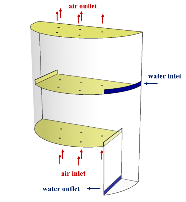
The flow of pure air travels upwards through five small circular holes embedded in the lower part of the chamber at a speed of 23.35 m.s-1 and exits through five open-facing holes at the top of the chamber; While the flow of pure water with a mass flow rate of 4 kg.s-1 enters the chamber through a side hole and exits through a hole embedded in the bottom of the model by moving downwards. The place for the two-phase contact is a tray modeled in the middle of the tower enclosure, which consists of five circular holes on its surface and water flows through it.
distillation column tray Geometry & Mesh
The present 3-D model is designed using Design Modeler software. The geometry of the model includes a chamber with a tray distillation tower. Due to the fact that the present model has a symmetrical structure, half of the chamber has been modeled to prevent the increase in the computational process.
The upper part of the designed chamber consists of a semicircular surface with a radius of 0.6065 m, which has a height of 1.22 m and is located on the lower part of the chamber with a height of 0.61 m. Inside the upper part of the chamber, an airflow inlet plate consisting of five small circular vents 0.02 cm in diameter, an airflow outlet plate consisting of the same five vents, and a center plate called a tray as the liquid flow contact point, and the gas consists of the same five holes and is designed next to the water inlet flow hole. The distance of this tray from its upper and lower plates is equal to 0.61 m.
The following figure shows a view of the geometry.
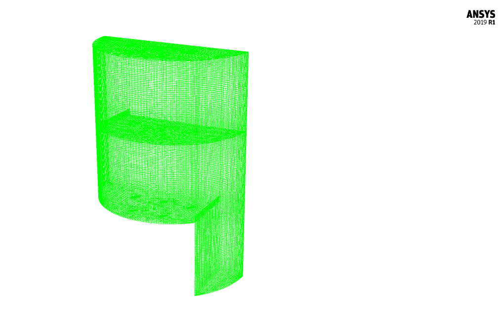
The meshing of the model has been done using ANSYS Meshing software and the mesh type is unstructured. The element number is 866590. The following figure shows the mesh.
Distillation Column Tray CFD Simulation
To simulate the present model, several assumptions are considered:
- We perform a pressure-based solver.
- The simulation is steady.
- The gravity effect on the fluid is equal to -9.81 m.s-2 along the z-axis.
A summary of the defining steps of the problem and its solution is given in the following table:
| Models | |||
| Viscous | k-epsilon | ||
| k-epsilon model | RNG | ||
| near-wall treatment | standard wall function | ||
| Multi phase Model | VOF | ||
| primary phase | air | ||
| secondary phase | water liquid | ||
| formulation | implicit | ||
| type of interface modeling | sharp | ||
| Boundary conditions | |||
| Inlet-Gas | Velocity Inlet | ||
| velocity magnitude | 23.35 m.s-1 | ||
| volume fraction – water | 0 | ||
| volume fraction – air | 1 | ||
| Inlet-Liquid | Mass Flow Inlet | ||
| mass flow rate – water | 4 kg.s-1 | ||
| mass flow rate – air | 0 kg.s-1 | ||
| Outlet-Gas | Pressure Outlet | ||
| gauge pressure | 0 Pascal | ||
| Outlet-Liquid | Pressure Outlet | ||
| gauge pressure | 0 Pascal | ||
| Walls | Wall | ||
| wall motion | stationary wall | ||
| Methods | |||
| Pressure-velocity coupling | SIMPLE | ||
| pressure | PRESTO | ||
| momentum | second-order upwind | ||
| volume fraction | modified HRIC | ||
| turbulent kinetic energy | first-order upwind | ||
| turbulent dissipation rate | first-order upwind | ||
| Initialization | |||
| Initialization methods | Standard-Patch | ||
| all zone | gauge pressure | 0 Pascal | |
| velocity (x,y,z) | 0 m.s-1 | ||
| water volume fraction | 0 | ||
| air volume fraction | 1 | ||
| patch | water volume fraction | 1 | |
| air volume fraction | 0 | ||
Results
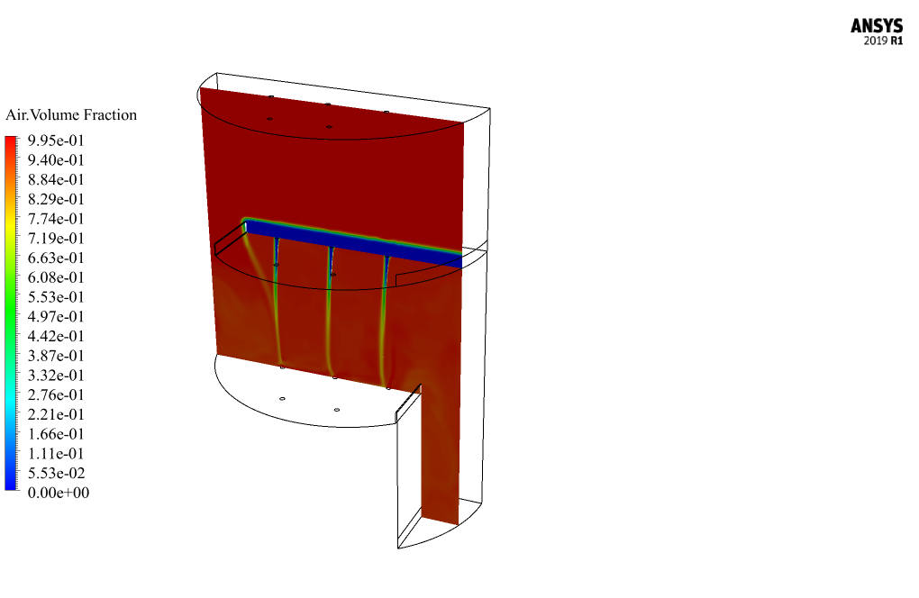
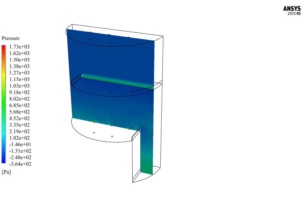
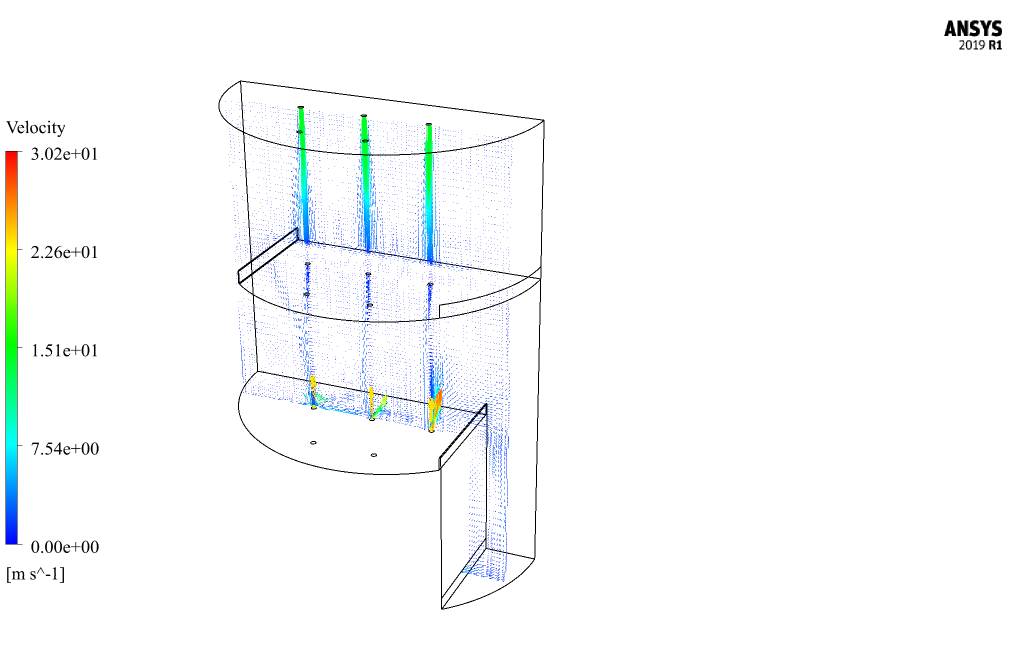
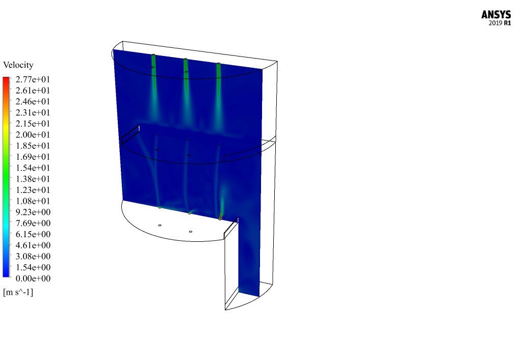
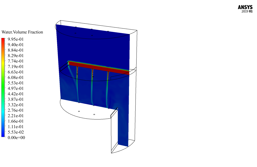
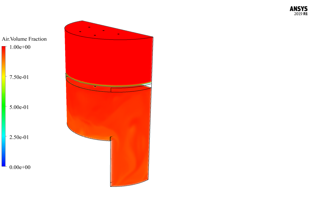
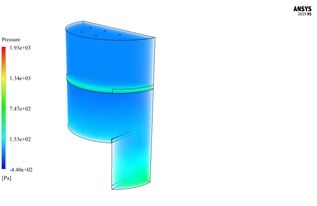
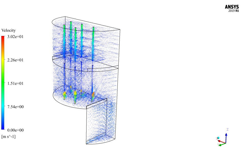
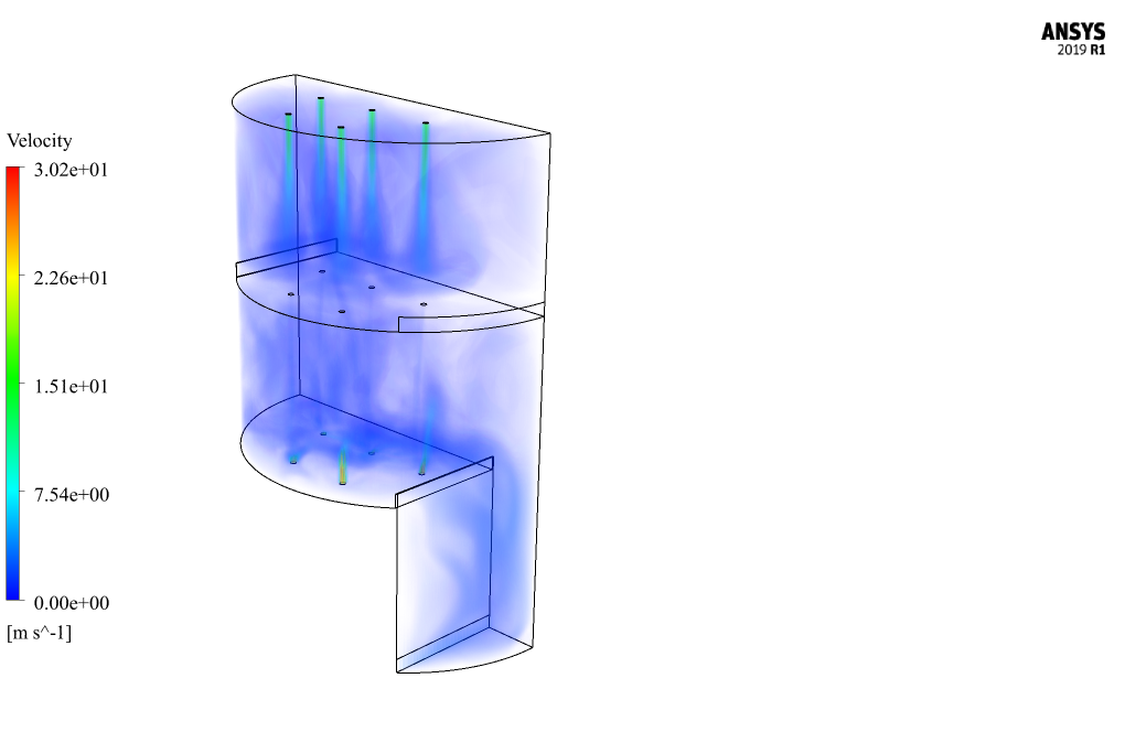
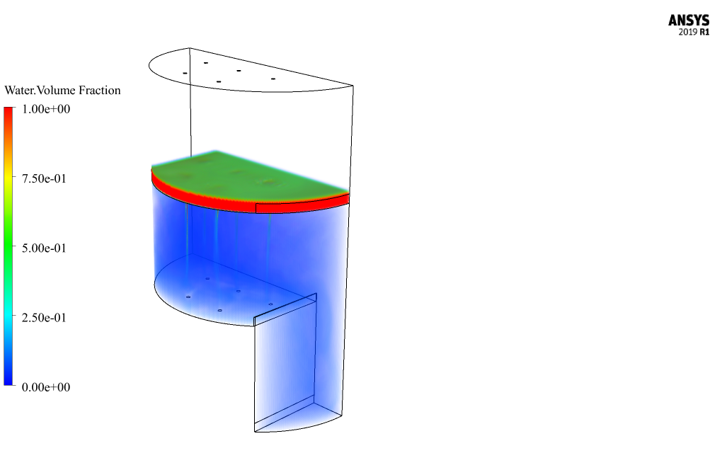
At the end of the solution process, two-dimensional and three-dimensional two-phase mixture pressure and velocity contours, volume fractions related to the water phase and gas phase, and mixture velocity vectors are obtained. The two-dimensional contours are drawn at a distance of 0.2 m from the center plane and passing through three holes for the passage of air flow.


Prof. Neal Hermann –
I am extremely impressed by the level of detail in the distillation column tray simulation. It seems like a comprehensive learning tool!
MR CFD Support –
We are delighted to hear that you appreciate the depth and meticulousness of the CFD simulation for the distillation column tray. Thank you for your positive feedback!
Braulio Turner –
The distillation column tray simulation is fascinating! I was wondering how exactly does the placement of the inlet and outlet ports affect the overall process efficiency in this model?
MR CFD Support –
In the context of this simulation, the placement of the inlet and outlet ports plays a crucial role in the efficiency of the process. The air enters from the bottom and rises through the column, while the liquid enters from the top. This setup maximizes the contact time and area between the air and water, allowing for better mixing and, hence, more effective phase separation. It’s implemented in a way to mimic the actual workings of an industrial distillation column, aiming for realistic performance insights.
Dr. Dorian O’Connell IV –
After going through the complete project description, I noticed thorough information about the setup and assumptions. What wasn’t addressed, though, is how the pressure affects the overall distillation process in the simulation. Could you please elaborate on that part?
MR CFD Support –
Pressure greatly affects the efficiency and operation of distillation processes. In our simulation setup within ANSYS Fluent, the air and water flows are considered at atmospheric pressure. The gravity effect and the interaction between the two phases at the tray easily offset this chosen approach, and it facilitates the separation process based on density differences. This mimics common industrial distillation operation conditions. For more precision in different scenarios where pressure varies significantly, the set-up can be adjusted in the boundary conditions to simulate pressure impacts accordingly.
Tobin Larson –
Is it possible for the model to simulate the influence of different temperatures on vapor-liquid equilibria in the distillation column?
MR CFD Support –
This simulation focused on the two-phase flow and did not specifically model heat transfer and temperature’s effect on vapor-liquid equilibria. To include temperature effects on separation efficiency, additional modeling such as energy equations and phase change mechanisms would be required.
Oran Crist –
What are the primary goals and expected outcomes from this distillation column tray simulation on a qualitative level?
MR CFD Support –
Thank you for reaching out with your question! The primary goals in this distillation column tray simulation are focused on studying the flow behaviors and interaction between the liquid (water) and gas (air) phases at the tray location, without accounting for heat transfer and evaporation processes. Expected qualitative outcomes include the understanding of separation efficiency and the effectiveness of the tray design in achieving proper contact between the phases. We can anticipate visualizing the distribution and mixing patterns of the two phases, gas flow uniformity through the vents, and any potential areas where design modifications could enhance the column’s performance.
Prof. Antonietta Kulas IV –
What results did you gain after the simulation regarding the efficiency of the separation process in the distillation tray?
MR CFD Support –
Our simulation did not specifically measure the efficiency of the separation process but focused on the behavior of the liquid and gas phases at the tray. However, based on the observed interaction and distribution of the phases in the contours and vector plots, it suggests a certain level of efficiency in mixing and potential separation. For a precise efficiency assessment, further analysis considering heat transfer and actual vapor-liquid equilibria would be necessary.
Prof. Hilton Adams IV –
What are the types of interface modeling used in this VOF simulation, and how does it affect the results?
MR CFD Support –
In this VOF simulation, a sharp type of interface modeling is used, which carefully tracks and maintains a distinct interface between the air and water phases. This sharp interface affects the results by providing clear delineation on the two-phase flow, enabling accurate prediction of interface dynamics and interactions between the phases, specifically within a tray in the distillation column.
Janet Cremin –
I’m really impressed with the clarity and detail provided in the two phase flow of air and water in a distillation column tray simulation. The technical aspect of how the hot steam and liquid interaction on the trays facilitates material separation is fascinating. The detailed explanation of the setup using a VOF multi-phase model gives a comprehensive idea of the simulated process without actual heat transfer and distillation simulation, which serves as an excellent basis for understanding the flow behaviors.
MR CFD Support –
Thank you for the positive feedback! We are glad that you find the level of detail in our distillation column tray simulation helpful and fascinating. It’s our aim to provide comprehensive learning materials that make complex concepts accessible and clear to our customers. Comments like yours inspire us to continue delivering high-quality simulations and training. Thank you for choosing our CFD simulation products for your educational needs!
Travon Bahringer –
The course description was comprehensive, but can you explain if the effects of surface tension were accounted for in this simulation, especially given the significant interface interaction between air and water?
MR CFD Support –
In this simulation, the VOF (Volume of Fluid) method was used to model the two-phase flow, which typically includes the effects of surface tension. The VOF method is well-suited for tracking and locating the fluid interface where air and water meet, which is where surface tension would be significant. However, the detail on how it was specifically accounted for in terms of numerical settings, or if additional measures were taken to fine-tune these interactions wasn’t mentioned in the description, but it is typically included in the physics of such simulations in ANSYS Fluent.
Mr. Presley Dickens Sr. –
What method is used to detect the interface between air and water in this simulation and why?
MR CFD Support –
The VOF (Volume of Fluid) model is used to detect the interface between the air and water in this simulation. VOF is particularly suited for tracking and locating the interface between two immiscible fluids and capturing the dynamic shape changes of the liquid-gas interface as the distillation process occurs in the tray column.
Alexandrine McLaughlin II –
Thank you for the detailed description of the Distillation Column Tray simulation training. I was wondering if the modeling accounts for surface tension effects between air and water, which could be crucial in distillation processes.
MR CFD Support –
In the simulation of the two-phase flow in a distillation column tray, the VOF model accounts for surface tension effects between air and water. This way, it can accurately represent the interface between the two fluids, critical for understanding the behavior of liquid and gas phases within the tray.
Viola Baumbach –
The description provides detailed boundary conditions for both the gas and liquid inlets, and for the outlets as well. I would like to know, is there a specific reason why RNG k-epsilon was selected over other turbulence models for this simulation?
MR CFD Support –
The RNG k-epsilon turbulence model is chosen over other turbulence models due to its enhanced reliability and accuracy for flows involving recirculation and complex streamline curvatures, which are typical in a distillation column tray scenario involving two-phase flow. This model provides more accurate details for highly swirling flows observed within the column.