Conjugated Heat Transfer, Elliptical Finned Tube Heat Exchanger Vs. Circular Fin
$160.00 Student Discount
In this project, by investigating conjugated heat transfer, the effect of cross-sectional change (with the constant area) on the rate of improvement of heat flux passing through the circular and elliptical finned tube heat exchanger was compared.
Click on Add To Cart and obtain the Geometry file, Mesh file, and a Comprehensive ANSYS Fluent Training Video.To Order Your Project or benefit from a CFD consultation, contact our experts via email ([email protected]), online support tab, or WhatsApp at +44 7443 197273.
There are some Free Products to check our service quality.
If you want the training video in another language instead of English, ask it via [email protected] after you buy the product.
Description
Introduction
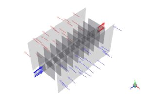
The use of heat exchangers in the oil and gas industry and power plants is prevalent. Finned tube heat exchangers are used to cool the desalinated crude oil. These heat exchangers ameliorate heat transfer by increasing the effective surface area due to the high fins and creating more turbulence in the flow. Fins are used when the working fluid in contact with that part has a lower heat transfer coefficient. The following figure shows an example of this type of heat exchanger.
Problem Description
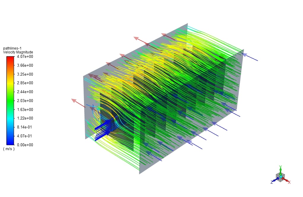
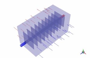
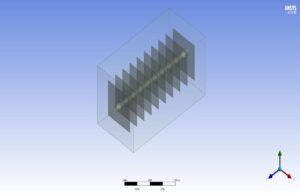
In this project, the effect of cross-sectional change (with the constant area) on the rate of improvement of heat flux passing through the finned tube heat exchanger was compared by investigating conjugated heat transfer. Ansys Fluent software was used for the simulation. Two circular and elliptical sections with equal cross-section areas are examined for the internal fluid section. One row of this type of finned tube heat exchanger was modeled to reduce the computational costs. The hot inlet fluid was crude oil with a temperature of 200 ° C and a velocity of 0.3 m / s. Air fluid with a temperature of 25 ° C and velocity of 2 m / s was used for the external flow section. The figure below shows the computational domain of the simulation.
Finned Tube Heat Exchanger Geometry & Mesh
The geometry was designed using the Design modeler module (figure below). Its geometric specifications consist of a pipe with a diameter of 10, a thickness of 1 and a length of 100 cm, and square fins with a side of 30 cm. For the elliptical case, the length of the large-diameter was 10, and the small diameter was 2.5 cm. The thickness of the fins was 0.5 cm and at a distance of 20 cm from each other, which makes a total of 10 fins.
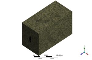
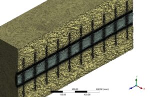
For grid generation, unstructured mesh with about 5 million elements in the Ansys meshing module was used. In addition, a boundary layer mesh was used near the walls to satisfy the Y-Plus number condition of the enhanced wall treatment. The following figure shows the meshing geometry.
Solver Setting
Fluent software was used to solve the governing equations numerically. The problem is analyzed steady, using the pressure-based method and neglecting the gravitational effects.
Boundary conditions and Solution methods
Also, The table below shows the characteristics and values of boundary conditions, along with the models and hypotheses.
| Material Properties (crude oil) | |
| Amount | Fluid properties (water) |
| 877.1 | Density |
| 1800 | Specific heat |
| 0.13 | Thermal conductivity |
| 0.0082 | viscosity |
| Boundary Condition (Finned Tube Heat Exchanger) | |
| Type | Amount (units) |
| Velocity inlet (crude oil at 200 C) | 0.3 m/s |
| Velocity inlet (air at 25 C) | 2 m/s |
| pressure outlet (gauge pressure) | 0 pa |
| Cell zone condition | |
| solid | fluid |
| Fin (copper) | Air, crude-oil |
| Turbulence models (Finned Tube Heat Exchanger) | ||
| K- | viscous model | |
| realizable | K- model | |
| Enhanced wall treatment | Wall function | |
| Solution methods (Finned Tube Heat Exchanger) | ||
| Simple | pressure velocity coupling | |
| Second-order | pressure | spatial discretization |
| Second-order upwind | momentum | |
| First-order upwind | turbulent kinetic energy | |
| First-order upwind | turbulent dissipation rate | |
| Second-order upwind | energy | |
| Initialization (Finned Tube Heat Exchanger) | ||
| standard | initialization method | |
| 0 (Pa) | gauge pressure | |
| 0 (m/s) | y-velocity | |
| 0 (m/s) | x-velocity , z-velocity | |
| 30 C | Temperature |
Finned Tube Heat Exchanger Results
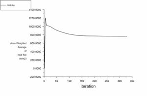
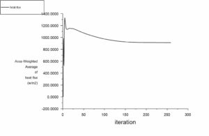
In this section, by examining the heat flux passing through the finned tube wall for both circular and elliptical cross-sectional surfaces, it was observed that the cross-sectional change from circular to elliptical increased the heat flux passing through the heat exchanger(Figure below).
Circular Finned Tube Heat Exchanger Heat Flux
Elliptical Finned Tube Heat Exchanger Heat Flux
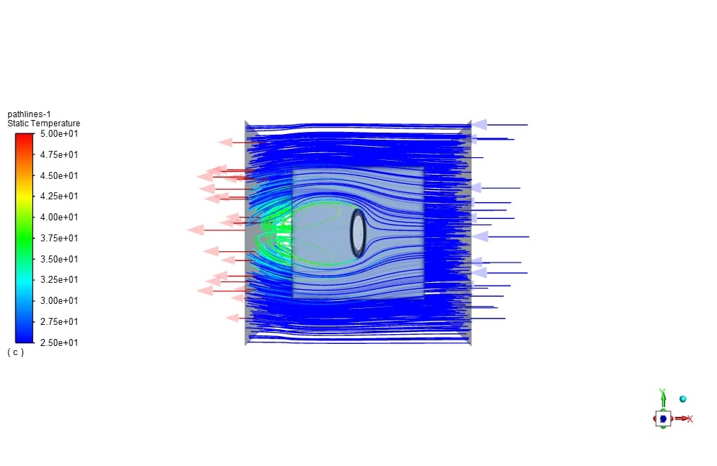
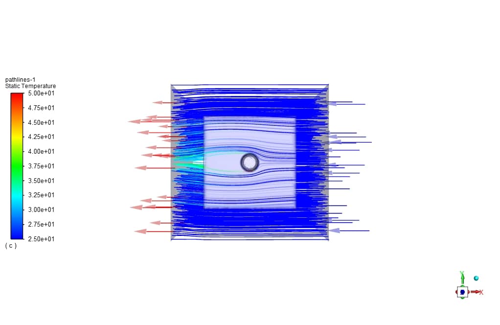
The main reasons for this improvement in heat transfer are the increase in the effective surface contact with the airflow due to the elliptical cross-section and the increment in the intensity of the flow turbulence when using the elliptical cross-section.
| type | Total surface heat flux (W/m2) |
| Circular section | 764.91 |
| Elliptical section | 911.39 |
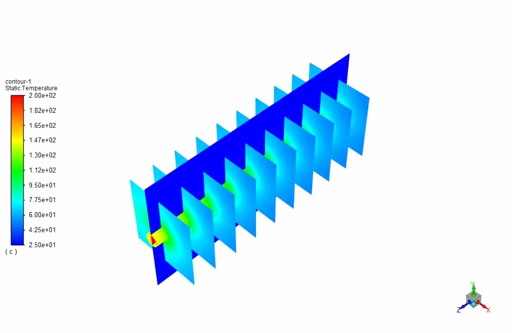
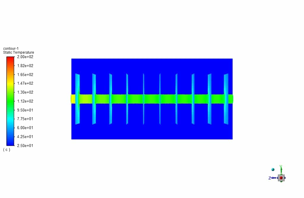
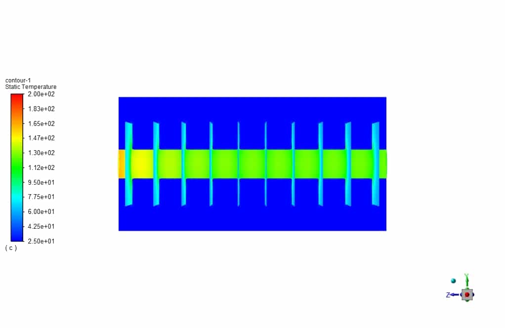
Also, by observing the temperature contours on the wall of the heat exchanger, it was found that a higher temperature distribution was created for the ellipse section in the fins.




Christ O’Hara –
The learning material is incredibly thorough and covers a range of critical topics. I’m especially impressed by the comparison between circular and elliptical finned tubes, as it gives clear insights into efficiency advancements. The inclusion of mesh geometry and solver settings is greatly appreciated, it provides a practical perspective on preparing and executing simulations.
MR CFD Support –
Thank you for your kind words! We are thrilled to hear that the learning material has provided you with a comprehensive understanding and practical insight on the topic. Your feedback is invaluable to us. If you have any more questions or need further assistance, feel free to reach out!
Dr. Gerhard Kutch –
I was thoroughly impressed by the increase in heat flux when transitioning from a circular finned tube to an elliptical one. Your detailed analysis and clear presentation of the results in this CFD simulation really expanded my understanding of how subtle changes in geometry can have significant impacts on heat transfer efficiency. Keep up the excellent work!
MR CFD Support –
Thank you for your kind words! We are delighted that our product has enriched your knowledge about heat transfer efficiencies in finned tube heat exchangers. If you have further interests or need assistance in any upcoming projects, don’t hesitate to reach out!
Jalen McKenzie –
The results show an increase in heat flux for the elliptical finned tube. Does this mean the elliptical option is always better than the circular one for all applications?
MR CFD Support –
While the elliptical finned tube showed an improvement in heat transfer compared to the circular one in this scenario, the elliptical option is not universally better for all applications. The decision to use a circular or elliptical finned tube depends on several factors like the specific heat exchanger design criteria, space constraints, flow characteristics and the particular thermal requirements of an application. Each design has its own advantages and should be selected based upon a detailed analysis of the particular system it will be used in.
Tavares Towne –
The details on heat transfer increase when using an elliptical section as opposed to a circular one are fascinating! The comparison between flow turbulence and surface contact effectiveness is very insightful.
MR CFD Support –
Thank you so much for your feedback! We’re glad to hear that you found the comparison insightful and that our product could provide valuable information to better understand the effects of fin geometry on heat exchanger performance. Your satisfaction with the learning materials motivates us to continue delivering high-quality content.
Arjun Moen –
This product’s comparison between circular and elliptical fins was insightful. The increase in heat flux with the elliptical section is particularly interesting. It’s great to see a practical use of CFD for optimizing thermal performance.
MR CFD Support –
Thank you for your positive review. We’re delighted to hear that you found the comparison between circular and elliptical fins in our heat exchanger simulation insightful. We aim to provide useful and practical CFD analysis for our customers. Your feedback is appreciated!
Ottilie Huel –
The review is really positive. I was amazed by the outcomes highlighting efficiency improvements in the elliptical finned design. Such a comprehensive analysis strengthens my understanding of heat transfer enhancement!
MR CFD Support –
Thank you so much for your kind words and positive feedback! We’re delighted to hear that our product has provided you with a deeper understanding of heat transfer enhancement in finned tube heat exchangers. Your satisfaction is our top priority, and we’re glad that the simulation results were clear and informative. If you have any more questions or need further assistance in your learning journey, please feel free to reach out to us!
Elyse Gislason Jr. –
Could you please clarify if the increase in heat flux for the elliptical fin was solely due to the change in shape, or were there other modifications made to the design as well?
MR CFD Support –
No modifications other than the shape of the fins from circular to elliptical were made. The increase in heat transfer efficiency for the elliptical finned tube is attributed to the change in shape, which increases the effective surface area in contact with the airflow and enhances flow turbulence, leading to improved heat flux without altering the cross-sectional area of the fins.
Eva Davis –
I was impressed with the analysis on the finned tube heat exchanger. Can you explain how different geometries, like the elliptical shape, improve the heat transfer compared to traditional circular shapes?
MR CFD Support –
I am so happy to hear your interest! Indeed, when we talk about heat exchange, geometry plays a crucial role. An elliptical shape can improve heat transfer compared to a circular one primarily due to two factors: enhanced surface area and improved turbulent flow. The elliptical geometry increases the surface area that’s in contact with the flowing fluid. Additionally, the shape disrupts the flow more than a circular section, leading to increased turbulence near the tube surface. This turbulence enhances the mixing of the boundary layer, which may improve the heat transfer rate. In summary, the advantage over the circular design comes from a combination of greater surface area in contact with the fluid and a more disruptive flow, which together contribute to the observed increase in heat flux for finned tube heat exchangers with an elliptical cross-section.
Mylene Schneider –
Were any enhancements added to the basic models for better prediction of the heat transfer phenomena in this study?
MR CFD Support –
The customized enhancements added to the basic models for better prediction of the heat transfer phenomena included the application of the realizable k-epsilon viscous model with enhanced wall treatment and use of second-order discretization methods to improve prediction accuracy.
Alexa Powlowski –
Compared to the circular finned tube, how does the elliptical design enhance the turbulence intensity that contributes to improved heat transfer?
MR CFD Support –
In the elliptical finned tube design, the asymmetry of the ellipse cross-section promotes more disturbance as fluid flows over it compared to a circular section. This generates additional turbulence, which enhances mixing and disrupts the boundary layer more effectively, thereby increasing the heat transfer from the tube’s surface.
Prof. Mose Hamill –
I got confused about whether the results for the pressure outlet and the initialization imply zero gauge pressure and zero velocity. Could you please clarify this for me?
MR CFD Support –
Yes, you are correct in your understanding. For the pressure outlet, a gauge pressure of 0 Pa means that the outlet pressure is set as the atmospheric pressure for the simulation. Likewise, during initialization of the simulation, setting 0 (m/s) for y-velocity, x-velocity, and z-velocity entails that the initial guess before the calculations start assumes the fluid is at rest with no initial movement.
Kristin Huels –
This learning product explains the differences in heat transfer performance between circular and elliptical finned tube heat exchangers. The comprehensive comparison covers key aspects like surface heat flux and temperature distribution on the wall of the heat exchanger, allowing us to understand the factors contributing to efficiency in each design.
MR CFD Support –
Thank you for taking the time to provide your positive feedback! We’re glad to hear that you found the comparison between circular and elliptical finned tube heat exchangers insightful and that it helped in understanding the thermal performance attributes of each design. Your recognition of the comprehensive nature of the explanation confirms our commitment to offering high-quality and informative content. If you have any further questions or need additional information, please don’t hesitate to reach out!