FCC Riser Gas-Solid Separation System Simulation
$120.00 Student Discount
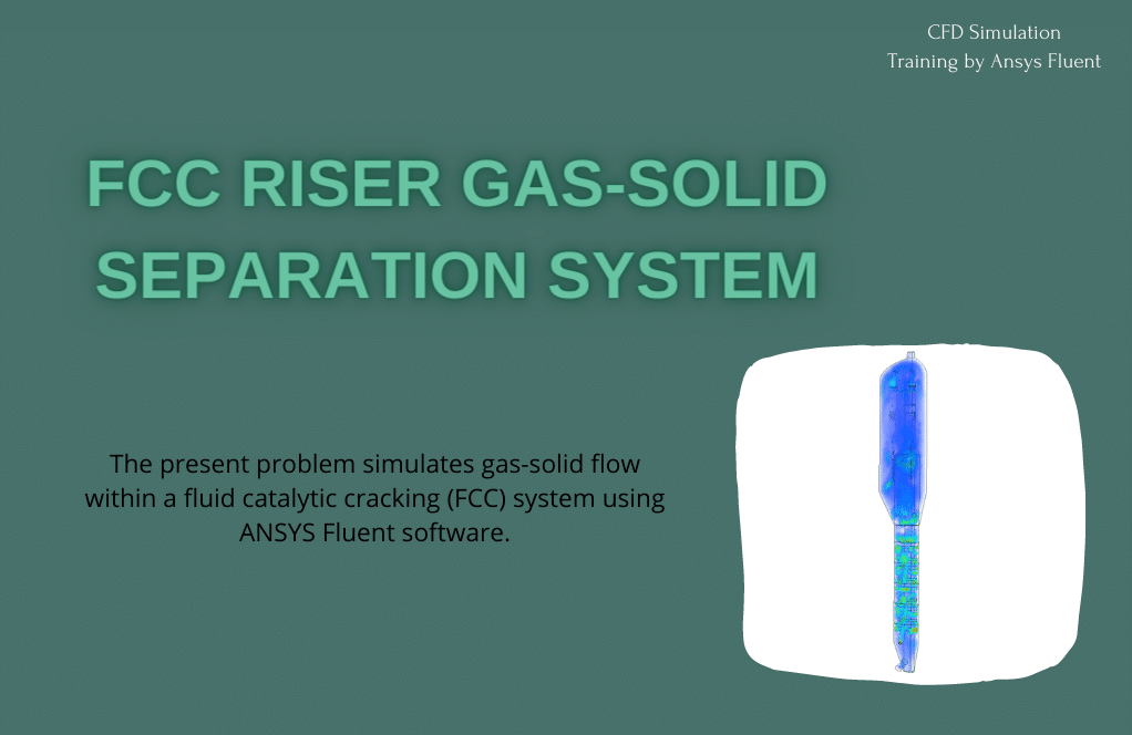
The present problem simulates gas-solid flow within a fluid catalytic cracking (FCC) system using ANSYS Fluent software.
Click on Add To Cart and obtain the Geometry file, Mesh file, and a Comprehensive ANSYS Fluent Training Video.To Order Your Project or benefit from a CFD consultation, contact our experts via email ([email protected]), online support tab, or WhatsApp at +44 7443 197273.
There are some Free Products to check our service quality.
If you want the training video in another language instead of English, ask it via [email protected] after you buy the product.
Description
FCC Riser Gas-Solid Separation System, CFD Simulation, ANSYS Fluent Training
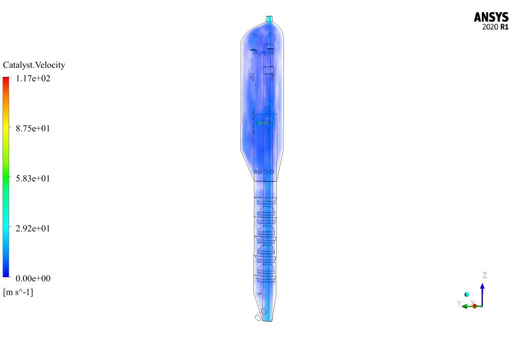
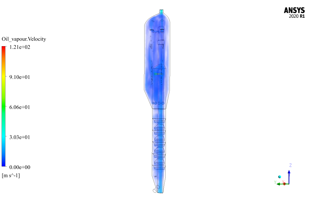
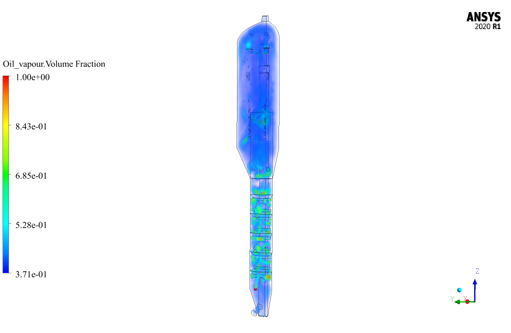
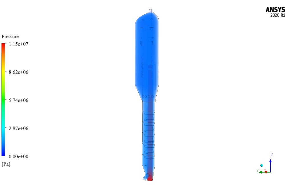
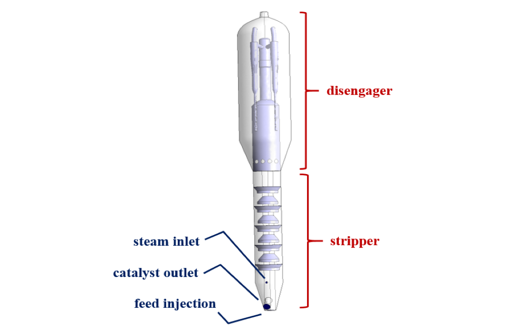
The present problem simulates gas-solid flow within a fluid catalytic cracking (FCC) system using ANSYS Fluent software. These FCC systems have many applications in chemical process units that are used to convert high-boiling oil ratios to lighter high-value products optimally. Inside FCC reactors, two important separate areas are defined, including a dilute area called the disengager and a dense area called the stripper. The disengager section is located in the upper part of the cylindrical chamber of the FCC reactor, which is responsible for separating the oil vapor from the catalyst particles. Therefore, in simulating this model, Eulerian multiphase flow is used.
This multiphase model can solve the momentum and conservation equations for each of the phases separately. Two materials are defined for this multiphase flow; So that oil vapor as a primary phase has a density equal to 3.471 kg.m-3 and a specific heat capacity equal to 1006.43 j.kg-1.K-1 and a thermal conductivity equal to 0.0242 Wm-.K-1, and a certain catalytic material as a secondary phase has a density equal to 1500 kg.m-3 and a specific heat capacity and thermal conductivity based on kinetic theory.
The oil vapor flow enters the reactor chamber from a special steam inlet with a velocity of 5.5 ms-1 and a temperature of 300 K, and a catalytic flow with oil vapor enters the feed injection inlet with a velocity of 18.57 ms-1 and a temperature of 300 K enter the chamber. The simulation process is performed with an unsteady solver for 20 seconds with a time step of 1 second.
FCC Geometry & Mesh
The present model is designed in three dimensions using Design Modeler software. The present model is a cylindrical reactor in which only a quarter of its geometric, symmetrical structure is designed to reduce computational costs. The upper part of the model is related to the disengager, and the lower part is related to the stripper.
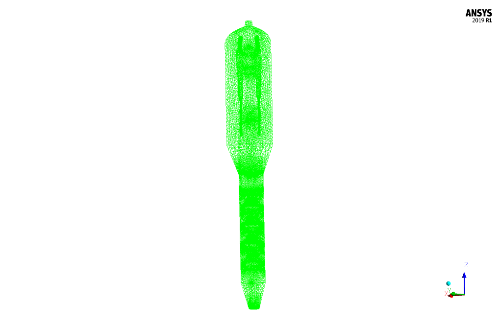
The meshing of the model has been done using ANSYS Meshing software, and the mesh type is unstructured. The element number is 2488759. The following figure shows the mesh.
FCC CFD Simulation
We consider several assumptions to simulate the present model:
- We perform a pressure-based solver.
- The simulation is unsteady.
- The gravity effect on the fluid is equal to -9.81 m.s-2 along the Z-axis.
The following table represents a summary of the defining steps of the problem and its solution:
| Models | |||
| Viscous | k-epsilon | ||
| k-epsilon model | standard | ||
| near wall treatment | standard wall functions | ||
| Multiphase model | Eulerian | ||
| formulation | implicit | ||
| number of Eulerian phases | 2 (oil vapor & catalyst) | ||
| Energy | On | ||
| Boundary conditions | |||
| Steam Inlet | Velocity Inlet | ||
| oil vapor | velocity magnitude | 5.5 m.s-1 | |
| temperature | 300 K | ||
| catalyst | velocity magnitude | 0 m.s-1 | |
| temperature | 300 K | ||
| Feed Injection | Velocity Inlet | ||
| oil vapor | velocity magnitude | 18.57 m.s-1 | |
| temperature | 300 K | ||
| catalyst | velocity magnitude | 18.57 m.s-1 | |
| temperature | 300 K | ||
| Product Outlet | Pressure Outlet | ||
| gauge pressure | 0 pascal | ||
| Inner Walls | Wall | ||
| wall motion | stationary wall | ||
| thermal condition | coupled | ||
| Baffles, disengager, stripper | Wall | ||
| wall motion | stationary wall | ||
| heat flux | 0 W.m-2 | ||
| Methods | |||
| Pressure-Velocity Coupling | Phase Coupled SIMPLE | ||
| Pressure | PRESTO | ||
| momentum | second-order upwind | ||
| turbulent kinetic energy | second-order upwind | ||
| turbulent dissipation rate | second-order upwind | ||
| volume fraction | quick | ||
| energy | second-order upwind | ||
| Initialization | |||
| Initialization methods | Standard | ||
| gauge pressure | 0 pascal | ||
| z-velocity for oil vapor | 18.57 m.s-1 | ||
| z-velocity for catalyst | 18.57 m.s-1 | ||
| temperature for oil vapor | 300 K | ||
| temperature for catalyst | 300 K | ||
| volume fraction for catalyst | 0.6 | ||
Harrison Grant –
I’m impressed by the level of detail in the simulation setup. Could you share more information on how the Eulerian multiphase model was configured, particularly how the interaction between phases was handled?
MR CFD Support –
Thank you for your feedback! In this simulation, the Eulerian multiphase model was configured to solve momentum and conservation equations for each phase independently while using inter-phase exchange coefficients to handle the direct interaction between the oil vapor and catalyst particles. Predictive mechanisms based on kinetic theory were implemented to calculate drag, turbulence dispersion, and virtual mass to properly model interactions like particle collisions and phase coupling. All of these factors contribute to creating a detailed representation of the multiphase flow in the FCC system.
Keeley Haley –
I’m completely impressed by the detail and accuracy of the FCC Riser simulation results. The contour visuals were especially illustrative and helpful for understanding the gas-solid flow dynamics.
MR CFD Support –
Thank you for your kind words! We’re thrilled to hear that our simulation results and contours were useful for your understanding of the process. It’s always our goal to provide detailed and accurate simulations that can be valuable learning tools. If you need any further assistance or have additional inquiries, don’t hesitate to reach out. Thank you for choosing our ANSYS Fluent training!
Ahmed Kilback DVM –
I truly appreciated the complexity of simulating a multiphase flow in an FCC system, and how well your product captures the detailed dynamics! It seems like a comprehensive tool for understanding gas-solid separations.
MR CFD Support –
Thank you for your positive review! Features such as modeling multiphase flow require meticulous attention, and we’re glad to know that you appreciate the accuracy and detail in our FCC simulation tool. Your feedback is highly encouraging for our team. If you need further assistance or information, please don’t hesitate to reach out.
Lois Stiedemann –
The training material did an excellent job explaining the FCC Riser simulation! The detailed parameters for the multiphase flow and separation process were particularly informative. Applying Eulerian multiphase models and solving momentum and conservation equations separately for each phase can be complex, but the content was concise and understandable. Keep up the good work!
MR CFD Support –
We really appreciate your positive feedback! It’s fantastic to hear that our material on the FCC Riser simulation was helpful and informative. Understanding multiphase flows is crucial for these simulations, and we’re delighted that you found the explanations clear. If you ever have more questions or need further information, please feel free to reach out. Thank you for taking the time to let us know!
Aleen Bruen –
In the simulation, how do you ensure the accuracy of the multiphase flow between oil vapors and catalyst particles?
MR CFD Support –
To ensure the accuracy of the multiphase flow between oil vapors and catalyst particles, the simulator uses the phase coupled SIMPLE method for pressure-velocity coupling. The momentum, turbulent kinetic energy, turbulent dissipation rate, energy, and volume fraction are all computed with second-order upwind schemes, which provide greater fidelity for capturing the flow characteristics. The use of the Eulerian multiphase model enables the separate solving of momentum and conservation equations for each phase, further enhancing accuracy.
Norris Swaniawski –
I am completely in awe of the FCC riser gas-solid separation system simulation’s detailed results at the end. The inclusion of dynamic phases and intricate model conditions showcases an impressive level of CFD work and team expertise at MR CFD Company.
MR CFD Support –
Thank you for your kind words! We’re thrilled to hear that you’re impressed with our detailed CFD simulation of the FCC riser gas-solid separation system and the results we’ve achieved. It’s our aim to provide the most accurate and comprehensive analysis, and your feedback is greatly appreciated. If you have any further questions or need assistance, please don’t hesitate to reach out.
Dr. Orval Lang II –
I’m curious, as the model assumes unsteady conditions, how does it guarantee convergence and accuracy over such a large timeframe of 20 seconds with only 1-second time steps? Are any specific techniques used to ensure stability in the numerical solution given the complexity of gas-solid flow in this FCC riser context?
MR CFD Support –
In FCC simulation involving unsteady gas-solid flow, achieving convergence and accuracy over 20 seconds with 1-second time steps requires carefully setting the solver parameters. The Phase Coupled SIMPLE algorithm aids in maintaining pressure-velocity coupling. Initial conditions are chosen methodically, ensuring a stable start to the iterative process. Adaptive time-stepping may also be utilized to ensure stability when more complex phenomena manifest, though this was not explicitly mentioned for this project. Rigorous monitoring of residuals and checking physical quantitates like mass and energy conservation aid in gauging the accuracy and convergence of the simulation over its duration, ensuring the stability of the numerical solution.
Miss Ivory Tillman DDS –
I’m truly impressed by the detailed and comprehensive explanation of the simulation results for the FCC Riser Gas-Solid Separation System. The precision and clarity of the model mesh, and the thoughtful consideration of parameters like velocity and temperature for the oil vapor and catalyst, truly highlight the depth of the simulation. Incredible work illustrating the complexity of such systems in a digestible format!
MR CFD Support –
Thank you very much for your thoughtful feedback and appreciation of the FCC Riser Gas-Solid Separation System CFD Simulation. It is exceptionally gratifying to know that the details and presentation of our simulation have impressed you and provided you with clear insights into such a complex process. Your recognition motivates us to continue delivering high-quality educational products.
Marcus Cormier III –
I really appreciate the detailed explanation provided for the FCC riser simulation. The applied methodologies and boundary conditions are well-explained. It’s interesting to learn how the multiphase flow is managed using the Eulerian model and how the gravity impact is taken into account. The meshing and boundaries set up seems thorough, achieving an attractive balance between accuracy and computational efficiency. Great job on conducting this with such an intensive element density, ensuring precise results for complicated gas-solid interactions!
MR CFD Support –
Thank you for your positive remarks! We’re delighted to know that you found the FCC riser simulation details comprehensive and informative. Our team strives to provide high-quality simulations that balance precision and efficiency. We’re glad that the explanation of our methodologies, including the Eulerian multiphase model and boundary conditions, was appreciated. If you have any further insights or require additional information, feel free to reach out. Your feedback is very valuable to us!
Sylvester Walter –
I’ve followed each step in this simulation, and it’s been a fantastic learning experience. The unstructured mesh and the utilization of Eulerian multiphase flow really helped elucidate the complexities of an FCC system. The level of detail provided in the results obviously shows the team’s dedication!
MR CFD Support –
Thank you for your positive feedback! We’re delighted to hear that our simulation has facilitated your learning experience and that you’ve successfully managed to navigate the complexities of an FCC system. Your encouragement is highly appreciated, and we’re here to provide even more detailed and informative simulations in the future. Keep learning and stay tuned for more!
Hailee Batz –
In this comprehensive FCC Riser Gas-Solid Separation System Simulation, can you explain the function and impact of using the Phase Coupled SIMPLE method for pressure-velocity coupling?
MR CFD Support –
The Phase Coupled SIMPLE method is used for pressure-velocity coupling in the FCC simulation to ensure pressure and velocity fields are solved in a coupled manner for both the gas and solid phases. This method enhances stability and accuracy when dealing with the interactions between different phases in the multiphase flow system.
Mr. Grayce Sanford II –
This product seems to be comprehensive. Is it sufficiently detailed for someone unfamiliar with CFD to follow the simulation process independently?
MR CFD Support –
Absolutely, our CFD simulations are designed to be user-friendly. They include step-by-step instructions and comprehensive explanations of each phase, ensuring that even beginners can follow along and understand the entire process.
Leonardo Hintz V –
The training product seems comprehensive, but I’m curious how the system accounts for possible clustering of catalyst particles, which can occur in dense-phase areas like the stripper?
MR CFD Support –
The simulation uses an Eulerian multiphase flow model, which separately solves momentum and conservation equations for each phase, allowing for detailed tracking of the interaction between the oil vapor and catalyst particles. Although the clustering of particles can be a complex phenomenon, factors such as particle-particle collision and kinetic theory can be incorporated into the model to appropriately simulate dense-phase behavior like that in the stripper section.
Ms. Leanna Macejkovic –
I just finished going through the learning materials for the FCC Riser Gas-Solid Separation System simulation. The level of detail and clarity in the step-by-step instructions drastically improved my understanding of multiphase flows in ANSYS Fluent. It was fascinating to learn how different properties and conditions affect the behavior within an FCC system!
MR CFD Support –
We’re thrilled to hear that our training material for the FCC Riser Gas-Solid Separation System simulation was able to enhance your understanding so significantly! Seeing our users attain a clearer perception of multiphase flows within ANSYS Fluent is a fantastic result for us. Thank you for sharing your positive experience, and we’re here if you need any further assistance or delve further into CFD analysis!
Ethelyn Lind –
The tutorial was incredibly insightful. I successfully applied the methods to my academic project on gas-solid separation.
MR CFD Support –
Thank you for your positive feedback! We are delighted to hear that our tutorial has been beneficial to your academic project. If you have any more questions or need further assistance, feel free to reach out. Best of luck with your project!
Consuelo Hansen –
I was impressed by the detailed setup in your FCC Riser Gas-Solid Separation System simulation! I particularly appreciated the considerations taken for the fine meshing to ensure accurate readings. This is crucial for understanding the intricate behaviors in an FCC unit. Great work showcasing the capabilities of CFD in complex process simulations!
MR CFD Support –
We’re thrilled to hear that our attention to detail and the thorough meshing process in the FCC Riser Gas-Solid Separation System simulation met your expectations! Ensuring the accuracy of our simulations is paramount to understanding complex systems, and we’re delighted to have your acknowledgment on these efforts. Thank you for your positive feedback!
Selena Schmeler –
The particle tracking feature was very impressive! Are the catalyst particles accurately represented in terms of size and shape too or are they assumed to be spherical for simplification?
MR CFD Support –
Thank you for your positive words. In the simulation, the catalyst particles are typically assumed to be spherical for simplification and to make the computational process more feasible. However, for detailed particle shape analyses, specialized discrete element methods (DEM) and other advanced techniques may be used in conjunction with CFD to capture the true morphology of the catalyst particles.
Milton Konopelski –
This training was fantastic! It helped me understand the simulation of gas-solid flow in FCC units clearly. Your approach to simulating different phases and setting up conditions is comprehensive and detailed, which makes it easier to grasp complex concepts. Thoroughly enjoyed learning through this practical example!
MR CFD Support –
Thank you for your kind words! We’re thrilled to hear that our training on FCC Riser Gas-Solid Separation System Simulation using ANSYS Fluent software was effective for your learning experience. We always strive to provide clear and detailed instruction to help our users grasp intricate concepts comfortably. If you have any more questions or need further assistance, don’t hesitate to reach out. Happy simulating!
Enid Mosciski –
The training and detail around the FCC Riser simulation are fascinating! The description mechanically details the steps and processes in such a comprehensive manner, making it easier to understand the complexities of gas-solid flows in these systems.
MR CFD Support –
Thank you for taking the time to review our FCC Riser Gas-Solid Separation System Simulation training product. We’re glad to hear that you found the detailed explanation beneficial and easy to understand. Your feedback is greatly valued, and we appreciate your support!
Ronaldo Kilback –
The training material certainly sounds comprehensive and practical for studying the gas-solid separation process in FCC systems. I appreciate the detailed setup description, which ensures clarity for anyone interested in computational fluid dynamics. Cheers to MR CFD for providing such specialized and high-quality CFD training content!
MR CFD Support –
Thank you for your kind words! We’re thrilled to know that you find our training material on the FCC Riser Gas-Solid Separation to be comprehensive and useful. MR CFD is committed to providing high-quality and in-depth learning experiences for CFD enthusiasts and professionals. Your acknowledgment motivates us to continue delivering top-notch educational content.
Margot Breitenberg –
I’m impressed by the level of detail in the multiphase flow simulation—especially the separation process in the FCC riser. Could you share what kind of post-processing tools were used to analyze the results? Animations, graphs, contour plots?
MR CFD Support –
In the post-processing stage of FCC riser simulation, several tools were used to analyze and visualize the results effectively. We utilized contour plots to display the pressure, velocity, and volume fraction distributions across the different phases. Furthermore, time-dependent results analysis like animations was employed to visualize the flow behavior over the 20-second simulation period. Lastly, graphical plots were used to analyze temporal changes in key variables such as pressure and velocity to understand the separation efficiency throughout the simulation time.
Aaliyah Kunze –
I found the simulation of the gas-solid flow in the FCC system fascinating and was wondering if there is any visual or plot information on the separation efficiency at different time intervals during the simulation?
MR CFD Support –
Thank you for your interest in our training materials! Regarding your question, indeed, we provide in our results comprehensive visual plots illustrating the efficiency and behavior of separation at various stages throughout the simulation. These visuals typically include time-specific snapshots that show the pressure, velocity and volume fraction of each phase. Monitoring these contours over various time steps can reveal insights into separation efficiency and overall process dynamics.
Maureen Williamson Jr. –
I was impressed by the thorough approach to the analysis of the FCC riser gas-solid separation system simulation. The detailed description of boundary conditions and the use of Eulerian multiphase flow to model the interaction between oil vapor and catalyst particles was clearly elucidated. Furthermore, the mesh quality and the implementation of various numerical schemes like PRESTO for pressure and second-order upwind for momentum speaks to the integrity of the simulation accuracy. Outstanding work by MR CFD Company in offering quality educational materials for complex CFD concepts.
MR CFD Support –
Thank you for your positive feedback! We strive to provide comprehensive CFD learning materials that detail every step of the simulation process to help our customers understand and apply complex concepts effectively. We’re thrilled to hear that you appreciated the depth of the analysis and found our training content valuable. If you have any more questions or need further assistance with CFD simulations, feel free to reach out to us!
Krystina Blanda –
The details of the simulation process for the FCC Riser were extremely helpful! It was fascinating to see how the meshing was done and how the multiphase model used the Eulerian approach for separate phase calculations. The explanation of the boundary conditions also provided a clear understanding of how the system was going to replicate the complex gas-solid interactions in a real-life FCC chamber.
MR CFD Support –
Thank you for your positive feedback! We’re glad to hear that our detailed explanation of the simulation process was helpful and provided clear insights into the complexities of gas-solid interactions within a Fluid Catalytic Cracking system. If you have any further questions or need more information, feel free to ask!
Prof. Deshaun O’Reilly III –
Magnificent course! I fondly appreciated how the simulation thoroughly mimics the delicate processes within an FCC riser. The depth of analysis, particularly on how the disengager and stripper sections are simulated, is genuinely impressive. It showcases the capabilities of ANSYS Fluent in industrial applications. The complex interactions between the oil vapor and catalyst particles seem to have been captured very well. The results must offer great insights to professionals in the field.
MR CFD Support –
Thank you so much for your positive feedback! We are thrilled to hear that our FCC Riser Gas-Solid Separation System Simulation course met your expectations and provided valuable insights. Your appreciation motivates us to continue delivering high-quality simulation training that can be applied in real-world industry applications. We look forward to providing you with more learning opportunities in the future.
Garrison Runolfsson –
I was truly impressed by the complexity of the FCC Riser simulation work. The detailed set-up of the multiphase flow with applications to chemical process units is remarkably intricate.
MR CFD Support –
Thank you very much for your positive feedback! We strive to provide detailed and comprehensive simulations to ensure a valuable learning experience. It’s great to hear that our efforts in simulating the FCC Riser gas-solid separation system met your expectations.
Tiana Hermiston –
The outcomes from the FCC simulation are promising. It’s clear tremendous effort went into developing a detailed model, capturing the intricacies of the gas-solid separation process. Your team’s expertise in utilizing ANSYS Fluent is apparent in the meticulous setup and execution of the CFD simulation.
MR CFD Support –
Thank you for your kind words and appreciation of our work on the FCC riser gas-solid separation system simulation. We are delighted to know that the efforts and expertise of our team are visible in the execution of the project. Your feedback is invaluable to us.