Floating Vessel Motion in Water by Dynamic Mesh, ANSYS Fluent Training
$200.00 Student Discount
- The problem numerically simulates the Floating Vessel Motion in Water using ANSYS Fluent software.
- We design the 3-D model with the Design Modeler software.
- We mesh the model with ANSYS Meshing software, and the element number equals 902808.
- We perform this simulation as unsteady (Transient).
- We use the Dynamic Mesh model to define the instantaneous change of meshing.
- We use a UDF to define the motion with two degrees of freedom.
- We use the VOF Multiphase model and the Open Channel condition to define the water level inside the air.
Click on Add To Cart and obtain the Geometry file, Mesh file, and a Comprehensive ANSYS Fluent Training Video.
To Order Your Project or benefit from a CFD consultation, contact our experts via email ([email protected]), online support tab, or WhatsApp at +44 7443 197273.
There are some Free Products to check our service quality.
If you want the training video in another language instead of English, ask it via [email protected] after you buy the product.
Description
Description
The present problem simulates the motion of a floating vessel in the water by dynamic mesh method using ANSYS Fluent software. In this simulation, a computational domain of water with a certain height level is designed with a floating vessel on the water’s surface.
The present model is designed in three dimensions using Design Modeler software. The mentioned floating vessel is designed in the middle of three cubic computing domains.
For ease of simulation, the floating vessel should be designed so that its center of gravity is at the center of the vertical direction (z-axis).
The meshing of the model has been done using ANSYS Meshing software. The mesh type is unstructured near the floating vessel and structured in the other parts. The element number is 902808.
Floating Vessel Methodology
In such models, we need a momentary and time-dependent change in meshing based on the type of displacement at adjacent boundaries of grids.
Therefore, the Dynamic Mesh model defines the instantaneous change of meshing. Initially, a floating vessel was designed for this simulation, and three computational zones were generated around it. Smoothing and Remeshing methods have been used to determine dynamic mesh methods.
According to the smoothing method, the number of nodes or cell connections does not change and only adjusts the mesh of an area by moving or deforming the boundaries.
However, the remeshing method is used when the boundary displacement is large compared to the size of the local cells to reconstruct the destructive cells of the critical size limit.
Six degrees of freedom (6-DOF) have also been used to define the type of dynamic mesh behavior. The model can move and relocate in six transitional and rotational directions.
To define areas with a dynamic mesh, a small rectangular cube area (around the floating vessel) is created as a Moving area, and a slightly larger area around the moving section is defined as a Deforming area.
Finally, a large general area around these areas is designed to be a Stationary area. The floating vessel part and the moving area are defined as Rigid Bodies.
This means that the floating vessel and a limited moving area act as a rigid and integrated body and can be moved in a transitional or rotational manner without any change in meshing. Since the vessel has only two degrees of freedom and can only move up and down in the vertical direction (z-axis) or rotate around its central axis (y-axis), and has a constraint in other directions (It does not have any transitional or rotational motion), a UDF is used to define this type of motion with two degrees of freedom.
It should be noted that in the section’s settings related to the rigid body, the spatial coordinates of the center of gravity of the floating vessel and the axis of its rotation around itself must be defined. The vessel is defined as a floating object on the water’s surface.
The VOF multiphase flow model should be used; So that air is defined in the upper part of the computational domain and water in the lower part. Air and water phases flow at speeds equal to 1.44 m/s in the horizontal direction (x-axis) and exit at a pressure equivalent to atmospheric pressure.
At the outlet boundary of the model, the Open Channel condition is used to define the water level. Due to the main nature of the model based on the use of dynamic mesh, the simulation process should be defined in terms of time (Transient solver).
The present model performs the simulation process in 7 seconds with a time step of 0.01 seconds.
Floating Vessel Conclusion
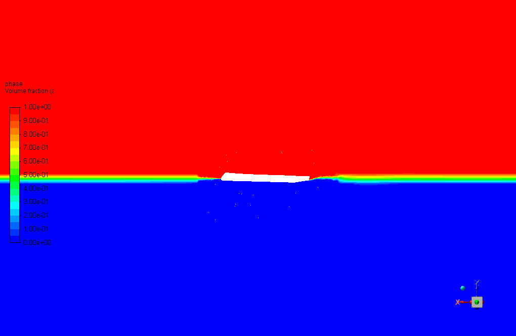
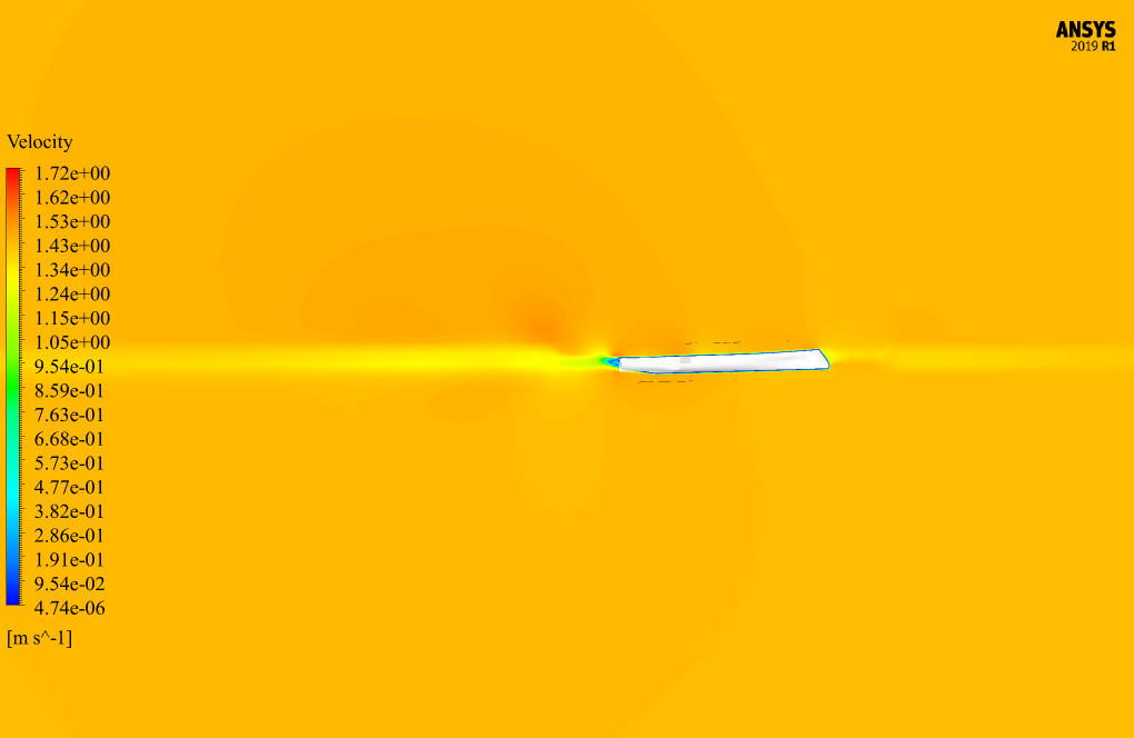
At the end of the solution process, two-dimensional contours related to the pressure on the floating vessel and two-dimensional contours related to the velocity and volume fraction of each air and water phase are obtained in the areas around the floating vessel.
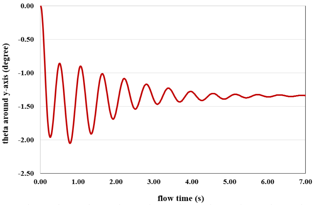
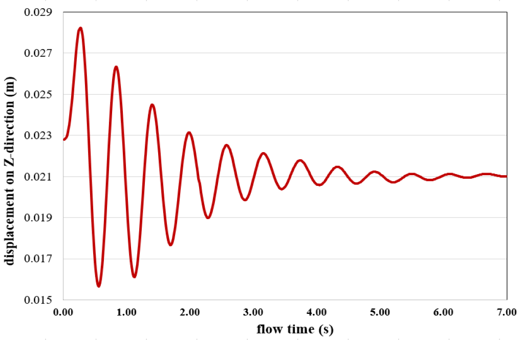
These contours correspond to the last second of the simulation process. Also, the graph of the amount of displacement of the vessel in the vertical direction (z-axis) in terms of time passage and the amount of rotation angle of the floating vessel around its central axis (y-axis) in terms of time are obtained.
These graphs show the angular and transitional spatial changes over 7 seconds. As the amplitude of the oscillation of the changes in the two graphs is clear, the changes reach their minimum in the seventh second, and we can say that the rotational and the transition motion are damped after this time.
Also, the figure shows that the floating vessel position in the seventh second at the position z = 0.021 and the angle Y_theta = -1.338 reaches stability.


Trey Bergstrom –
This training was exceptional! The focus on dynamic mesh and the detail involved in setting up for the simulations gave me solid insights into modeling floating body problems in ANSYS Fluent. The walkthrough of using a 6-DOF model and applying UDF for specific motion constraints was very educational. Thank you for such a comprehensive and understandable training material that has significantly bolstered my understanding of multiphase flow and floating vessel motion simulation.
MR CFD Support –
Thank you for your positive review! We are thrilled to hear that our training material on Floating Vessel Motion in Water by Dynamic Mesh exceeded your expectations. It’s great to know that you found the 6-DOF model discussions and the application of user-defined functions (UDFs) particularly informative. Your engagement and appreciation truly motivate us to continue providing in-depth and accessible simulation study materials. If you ever have any questions or need further assistance in your simulation endeavors, please feel free to reach out!
Evie Greenfelder –
I’m honestly impressed with the level of detail in this floating vessel simulation. The step-by-step methodology really helped me grasp the complexity of dynamic mesh and VOF for multiphase flow. Kudos!
MR CFD Support –
Thank you for your kind words! We’re thrilled to hear that our Floating Vessel Motion in Water simulation was so informative and engaging for you. It’s always our goal to deliver detailed and clear training modules. If you have any more feedback or need further assistance, please don’t hesitate to reach out!
Don Homenick –
The project description of the Floating Vessel Motion simulation by Dynamic Mesh is quite thorough! Is there a particular reason the simulation was run for 7 seconds? How was this duration decided?
MR CFD Support –
The choice of running the simulation for 7 seconds was likely based on ensuring that transient effects and the behavior of the vessel over time could be fully captured and the system could reach a steady state, or the settling of the vessel’s motion could be observed. This time frame allows the visualization of the vessel’s response to the forces acting upon it long enough to understand its damping characteristics and stability. The decision on duration is usually determined by the expected dynamic characteristics of the floating vessel and the need to observe multiple cycles of motion if it’s performing oscillatory movements.
Laura Vandervort –
I understood the approach used for the floating vessel, but I’m curious as to how the vessel’s center of gravity was determined for the simulation. Can you offer some insights into that process?
MR CFD Support –
In this simulation, the center of gravity of the floating vessel is considered to be in the center in the vertical direction (z-axis) to ensure stability and realistic motion. The exact coordinates are carefully calculated based on the design of the vessel and its distribution of mass. To ensure accurate dynamics, the center of gravity’s position is a critical factor that must be accurately known before the simulation begins. It’s ultimately defined in the rigid body settings to control the movement constraints and rotational capabilities of the vessel within the simulation.
Sigurd Gottlieb –
The training was utterly thorough and insightful! The interplay between the vessel dynamics and water forces was presented in a very palpable manner, articulating the simulation nuances impeccably. I also appreciated the clarity on setting up dynamic mesh boundaries and their interaction through the simulation. This undoubtedly enhances my comprehension of floating vessel simulation and aids significantly in my ongoing shipbuoyancy analysis.
MR CFD Support –
Thank you for your kind words! We’re thrilled to hear that the training was beneficial to you and that it provided clear guidance on dynamic mesh techniques in relation to floating vessel simulations. If you have any further questions or need additional assistance with ship buoyancy analysis or any other topics, please don’t hesitate to let us know. We’re here to help!
Kale Boehm Jr. –
Fantastic learning tool! The dynamic mesh detail provided excellent insight into vessel motion in water. The UDF inclusion for the vessel’s freedom of movement added a layer of complexity that enhanced my understanding. Excellent simulation accuracy. The contours at the simulation’s end vividly depicted the vessel’s pressure points and fluid interaction—very helpful for visual learners!
MR CFD Support –
Thank you for your positive feedback! We’re thrilled to hear that the detail and complexity of the dynamic mesh and UDF in our simulation contributed to a deeper understanding of vessel motion. It’s great to know that the visuals at the end of the simulation were also helpful. We really appreciate you taking the time to share your experience with our simulation training. Your satisfaction is our top priority!
Dr. Moises Ruecker –
The training material on the Floating Vessel Motion in Water by Dynamic Mesh in ANSYS Fluent was impressive. Especially the intricate detailing of the dynamic mesh technique and showcasing how it can adapt to the motion of the floating vessel in real-time was very informative. The use of 6-DOF to illustrate the full range of the vessel’s possible movements provided a clear understanding of the subject matter.
MR CFD Support –
Thank you for your positive feedback! We’re thrilled to hear that you found the information on the dynamic mesh technique and the application of the 6-DOF model in the Floating Vessel Motion simulation to be clear and informative. It’s always our goal to provide comprehensive and detailed learning material that empowers our customers to achieve great results. Your appreciation truly motivates us to keep delivering high-quality training products. Thank you for choosing MR CFD Company.
Dr. Virginie Pagac MD –
The detailed explanation for simulating the motion of a floating vessel is excellent! The application of dynamic mesh to capture the movement and the fluid’s interactions is impressive. I would like to know if the CFD model accounts for the corrector forces like spring and dampers in the six degrees of freedom (6-DOF) setup.
MR CFD Support –
In this CFD simulation, the 6-DOF model enables movement in all translational and rotational directions. However, details regarding the implementation of corrector forces like spring and dampers aren’t specified in the provided description. These are system-specific features that can be included in a 6-DOF setup to simulate realistic scenarios. You might need to refer to the detailed simulation setup or consult with engineering experts to understand if such corrector forces have been employed as part of the simulation model employed by MR CFD.
Olen O’Connell I –
The training on floating vessel motion simulation using dynamic mesh in ANSYS was truly impressive. The detailed methodology and clear explanation of concepts like the 6-DOF and the implementation of the VOF multiphase model were particularly insightful. Seeing the actual displacement and rotation of the vessel graphed out over time gives a clear picture of the concepts applied in a dynamic setting. It’s evident that the substantial effort was put into not just executing the simulation but also in making sure it could be understood and replicated. Excellent work on this training material!
MR CFD Support –
Thank you so much for your positive feedback! We’re thrilled to hear you found the floating vessel motion simulation training valuable and insightful. It’s great to know the explanations of the 6-DOF setup and the VOF multiphase model were clear and helpful. We strive to provide detailed and practical knowledge that can be understood and applied. We appreciate you recognizing the effort put into creating comprehensive training materials. Your kind words motivate us to continue delivering high-quality educational content. If you have any further questions or require more assistance, please let us know!
Liliana Barton –
How was the stability of the floating vessel ensured during the dynamic mesh simulation process? Was dampening applied to achieve the settled oscillation at the end of the simulation?
MR CFD Support –
The stability of the floating vessel during the dynamic simulation was maintained using the specifically defined center of gravity and the constraints on the movement of the vessel. Yes, dampening was applied as seen in the simulation results where the rotational and transitional motions reach a minimal amplitude by the seventh second, indicating that the oscillations are indeed damped to a stable position.
Juwan Stoltenberg –
I found the description of the dynamic mesh incredibly insightful for understanding vessel simulation in water. It’s amazing how technology can capture such complex interactions so accurately.
MR CFD Support –
Thank you for your positive feedback on the dynamic mesh description within our vessel simulation training. We take pride in providing insightful knowledge that resonates with our learners. It’s part of our commitment to ensure that each customer feels confident in the simulations they perform with our training materials.
Immanuel Powlowski –
The level of detail in the dynamics of the floating vessel is impressive. The use of Dynamic Mesh and the VOF multiphase model must have been challenging but it seems it was handled expertly to capture the vessel’s motion accurately. Well done on demonstrating a complex simulation with clarity and precision!
MR CFD Support –
Thank you for your positive feedback on our simulation training for the floating vessel motion in the water using the Dynamic Mesh method. It’s fantastic to hear that you appreciate the thoroughness of our details and the model’s complexity. We strive to deliver clear and precise learning materials, and your recognition is highly valued. Should you have any more inquiries or need further instructions, feel free to reach out!